Báo cáo hóa học: " Research Article Transmit Delay Structure Design for Blind Channel Estimation over Multipath Channels" pot
Bạn đang xem bản rút gọn của tài liệu. Xem và tải ngay bản đầy đủ của tài liệu tại đây (801.06 KB, 12 trang )
Hindawi Publishing Corporation
EURASIP Journal on Wireless Communications and Networking
Volume 2007, Article ID 26123, 12 pages
doi:10.1155/2007/26123
Research Article
Transmit Delay Structure Design for Blind Channel
Estimation over Multipath Channels
Tongtong Li,
1
Qi Ling,
1
and Zhi Ding
2
1
Department of Electrical and Computer Engineering, Michigan State University, East Lansing, MI 48824, USA
2
Department of Electrical and Computer Engineering, University of California, Davis, CA 95616, USA
Received 20 April 2006; Revised 16 October 2006; Accepted 11 February 2007
Recommended by Alex Gershman
Wireless communications often exploit guard intervals between data blocks to reduce interblock interference in frequency-selective
fading channels. Here we propose a dual-branch transmission scheme that utilizes guard intervals for blind channel estimation
and equalization. Unlike existing transmit diversity schemes, in which different antennas transmit delayed, zero-padded, or time-
reversed versions of the same signal, in the proposed transmission scheme, each antenna transmits an independent data stream.
It is shown that for systems with two transmit antennas and one receive antenna, as in the case of one transmit antenna and
two receive antennas, blind channel estimation and equalization can be carried out based only on the second-order statistics of
symbol-rate sampled channel output. The proposed approach involves no preequalization and has no limitations on channel-zero
locations. Moreover, extension of the proposed scheme to systems with multiple receive antennas and/or more than two transmit
antennas is discussed. It is also shown that in combination with the threaded layered space-time (TST) architecture and turbo
coding, sig nificant improvement can be achieved in the overall system performance.
Copyright © 2007 Tongtong Li et al. This is an open access article distributed under the Creative Commons Attribution License,
which permits unrestricted use, distribution, and reproduction in any medium, provided the original work is properly cited.
1. INTRODUCTION
Aiming for high spectral efficiency, recent years have wit-
nessed broad research activities on blind channel estima-
tion and signal detection. Although second-order statis-
tics of symbol rate sampled channel output alone can-
not provide enough information for blind channel estima-
tion, it is possible with second-order statistics of fractionally
spaced/sampled channel output or baud-r ate channel out-
put samples from two or more receive antennas [1–6]. These
are, in fact, early examples of blind channel identification
by exploiting space-time diversity techniques, the fr action-
ally spaced sampling takes advantage of time diversity, while
multiple receive antennas indicate spatial diversity at the re-
ceiver end.
Receive diversity has been widely used in mobile com-
munications (especially in the uplink) to obtain good system
performance while minimizing the power consumption at
the mobile handset. Exploitation of the transmit diversity, on
the other hand, is more challenging, mainly because signals
from multiple transmit antennas are mixed before they reach
the receiver, and special consideration needs to be taken to
separate these signals while allowing low-complexity receiver
design. In [7, 8], it is proved that for memoryless channels,
increasing the number of receive antennas in a SIMO system
only results in a logarithmic increase in the average capacity,
but the capacity of a MIMO system roughly grows linearly
with the minimum number of antennas placed at both sides
of the communication link. With the fundamental works in
[9–11], space-time coding and MIMO signal processing have
evolved into a promising tool in increasing the spectral effi-
ciency of broadband wireless systems.
In [9], a simple two-branch transmit diversity scheme
based on orthogonal design, the Alamouti scheme, is pre-
sented for flat fading channels. It is shown that the scheme
using two transmit antennas and one receive antenna can
achieve the same diversity order as using one transmit an-
tenna and two receive antennas. The Alamouti scheme is di-
rectly applicable to systems with multiple receive antennas
[9], and can be further extended to systems with any given
number of transmit antennas [12], where the latter extension
is generally referred to as space-time block coding. The trans-
mit delay diversity scheme, in which copies of the same sig-
nal are transmitted from multiple antennas at different times,
has been presented in [13, 14]. The transmit delay diver-
sity scheme can also achieve the maximum possible transmit
2 EURASIP Journal on Wireless Communications and Networking
diversity order of the system [15]. Space-time Trellis codes
were first developed in [11], and then refined by others, see
[16], for example. The layered space-time codes, represented
by the BLAST series, have been proposed in [10] and further
developed in [17, 18].
Most existing space-time diversity techniques have been
developed for flat fading channels. However, due to multi-
path propagation, wireless channels are generally frequency-
selective fading instead of flat fading. Extensions of space-
time diversity techniques suited for flat fading channels, es-
pecially the Alamouti scheme, to frequency-selective fading
channels can be briefly summarized as follows: (i) apply gen-
eralized delay diversity (GDD) [19] or the time reversal tech-
nique [20]; (ii) convert a frequency-selective fading chan-
nel into a flat fading channel using equalization techniques,
and then design space-time codes for the resulted flat fading
channel(s), see [21] for example; (iii) convert the frequency-
selective channels into a number of flat fading channels using
OFDM scheme, see [22] and references therein; (iv) reformu-
late the multipath frequency-selective fading system into an
equivalent flat fading system by regarding each single path as
a separate channel, see [23]forexample.
Space-time coded systems, which generally fall into the
MIMO framework, bring significant challenges to channel
identification. In fact, in order to fully exploit the space-time
diversity, the channel state information generally needs to be
estimated for all possible paths between the transmitter and
receiver antenna pairs. Training-based channel estimation
may result in considerable overhead. To further increase the
spectral efficiency of space-time coded system, blind chan-
nel identification and signal detection algorithms have been
proposed. In [24], blind and semiblind equalizations, which
exploit the structure of space-time coded signals, are pre-
sented for generalized space-time block codes which employ
redundant precoders. Subspace-based blind and semiblind
approaches have been presented in [25–28], and a family
of convergent kurtosis-based blind space-time equalization
techniques is examined in [29]. Blind algorithms based on
the MUSIC and Capon techniques can be found in [30, 31],
for example. Blind channel estimation for orthogonal space-
time block codes (OSTBCs) has also been explored in liter-
ature, see [32–34], for example. In [33],basedonspecific
properties of OSTBCs, a closed-form blind MIMO chan-
nel estimation method was proposed, together with a simple
precoding method to resolve possible ambiguity in channel
estimation.
Note that for frequency-selective fading channels, guard
intervals are often put between data blocks to prevent
interblock-interference, such as in the OFDM system [35],
the chip-interleaved block-spread CDMA [36], and the gen-
eralized transmit delay diversity scheme [19]. In this paper, a
simple two-branch transmission scheme, which is indepen-
dent of modulation (OFDM or CDMA) format, is proposed
to exploit the guard intervals for blind channel estimation
and equalization. The generalized delay diversity proposed in
[19] is perhaps the closest to our approach, but unlike [19],
and also [24, 27, 28], in which different antennas transmit the
delayed, zero-padded, or time-reversed versions of the same
signal, the proposed transmission scheme promises higher
data rate since each antenna transmits an independent data
stream.
Through the proposed approach, we show that with two
transmit antennas and one receive antenna, blind channel
estimation and equalization can be carried out based only
on the second-order statistics (SOS) of symbol-rate sampled
channel output. This result can be regarded as a counterpart
of the blind channel estimation algorithm proposed by Tong
et al. [6], which exploits receive diversity. However, unlike
[6], the proposed approach has no limitations on channel-
zero locations. This is because we have more control over the
data structure at the transmitter than at the receiver end, and
a properly structured transmitter design can bring more flex-
ibility to the corresponding receiver design.
With the proposed dual-branch transmitter design, when
more than one receive antennas are employed, the data rate
(in symbols/s/Hz, excluding training symbols or dummy ze-
ros)canbeincreasedbyafactorof2N/(N
+ L +1)(hereN
is the length of the data block and L is the maximum multi-
path delay spread, generally, N
L + 1) compared with that
of the corresponding SIMO system (under the same mod-
ulation scheme and with no training symbols transmitted).
A direct corollary of the proposed approach is that for SISO
systems, blind channel estimation based only on the second-
order statistics of the symbol-rate sampled channel output is
possible as long as the actual data rate (in symbols/s/Hz, ex-
cluding training symbols or dummy zeros) is not larger than
N/(N + L) times of the channel symbol rate. Theoretically, as
long as the channel coherence time is long enough, we can
choose N
L so that N/(N + L) can be arbitrarily close to
1.
The proposed scheme involves no preequalization, and
does not rely on the OFDM framework to convert the
frequency-selective fading channels to flat fading chan-
nels. Furthermore, in this paper, extension of the proposed
scheme to systems with more than two transmit antennas is
discussed, and it is also shown that in combination w ith the
threaded space-time (TST) architecture [17]andturbocod-
ing, significant improvement can be achieved in the overall
system performance.
2. THE PROPOSED STRUCTURED TRANSMIT
DELAY SCHEME
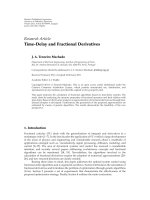
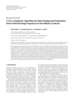
The block diagram of the proposed two-branch structured
transmit delay scheme with one receive antenna is shown
in Figure 1. The input symbols are first split by a serial-to-
parallel converter (S/P) into two parallel data streams; Each
data stream then forms blocks with specific zero-padding
structure. The data block structure depends on the channel
model and will be explained subsequently.
The structured data blocks,
a
k
and b
k
, are transmitted
through two transmit antennas over frequency-selective fad-
ing wireless channels, with channel impulse response vec-
tors denoted by h and g, respectively. The received signal is
therefore the superposition of distorted information signals,
Tongtong Li et al. 3
Input symbols
S/P
a
k
b
k
Zero
padding
Zero
padding
Tx-1:
¯
a
k
Tx-2:
¯
b
k
Channel h
Channel g
x
k
y
k
+
n
k
z
k
Figure 1: Two-branch transmit diversity with one receiver.
x
k
and y
k
, from each transmit antenna, and the additive
noise n
k
.
We assume that the two branches are synchronous and
the initial transmit delay is known in this section and in the
following two sections. We will discuss the extension of the
proposed transmitter design to the synchronous and asyn-
chronous cases with unknown delays, as well as the general
MIMO systems in Section 5.
Let L denote the maximum multipath delay spread for
both h and g. When the initial transmission delays are known
while the two branches are synchronous, without loss of gen-
erality, the channel impulse responses can be represented as
h
=
h(0), h(1), , h(L)
,
g
=
g(0), g(1), , g(L)
,
(1)
with h(0)
= 0, g(0) = 0.
Partition the data stream from each branch into N-
symbol blocks (N
≥ L+1), denote the kth block from branch
1andbranch2bya
k
= [a
k
(0), a
k
(1), , a
k
(N − 1)] and
b
k
= [b
k
(0), b
k
(1), , b
k
(N −1)], respectively. Zero-padding
is performed for each data block according to the following
structure. Define
a
k
=
⎡
⎢
⎣
a
k
(0), a
k
(1), , a
k
(N − 1), 0, ,0
L+1
⎤
⎥
⎦
,(2)
b
k
=
⎡
⎢
⎣
0, b
k
(0), b
k
(1), , b
k
(N − 1), 0, ,0
L
⎤
⎥
⎦
,(3)
and assume that there are M blocks in a data frame and
the channel is time-invariant within each frame. Trans-
mit [
a
1
, a
2
, , a
M
] from antenna 1 through channel h,and
transmit [
b
1
, b
2
, , b
M
] from antenna 2 through channel g.
With the notation that a
k
(n) = b
k
(n) = 0forn<0and
n>N
− 1, we have
x
k
(n) =
L
l=0
h(l)a
k
(n − l),
y
k
(n) =
L
l=0
g(l)b
k
(n − l − 1).
(4)
Define x
k
= [x
k
(0), x
k
(1), , x
k
(N + L)]
T
and y
k
= [y
k
(0),
y
k
(1), , y
k
(N + L)]
T
.Fork = 1, 2, , M, it follows that
x
k
=
⎡
⎢
⎢
⎢
⎢
⎢
⎢
⎢
⎢
⎢
⎢
⎢
⎢
⎢
⎢
⎣
h(0)
h(1) h(0)
.
.
.
.
.
.
h(L) h(L
− 1) ··· h(0)
.
.
.
.
.
.
.
.
.
h(L) h(L
− 1)
h(L)
0
⎤
⎥
⎥
⎥
⎥
⎥
⎥
⎥
⎥
⎥
⎥
⎥
⎥
⎥
⎥
⎦
H
⎡
⎢
⎢
⎢
⎢
⎣
a
k
(0)
a
k
(1)
.
.
.
a
k
(N − 1)
⎤
⎥
⎥
⎥
⎥
⎦
a
k
,
(5)
y
k
=
⎡
⎢
⎢
⎢
⎢
⎢
⎢
⎢
⎢
⎢
⎢
⎢
⎢
⎢
⎢
⎣
0
g(0)
g(1) g(0)
.
.
.
.
.
.
g(L) g(L
− 1) ··· g(0)
.
.
.
.
.
.
.
.
.
g(L) g(L
− 1)
g(L)
⎤
⎥
⎥
⎥
⎥
⎥
⎥
⎥
⎥
⎥
⎥
⎥
⎥
⎥
⎥
⎦
G
⎡
⎢
⎢
⎢
⎢
⎣
b
k
(0)
b
k
(1)
.
.
.
b
k
(N − 1)
⎤
⎥
⎥
⎥
⎥
⎦
b
k
,
(6)
where H and G are (N + L +1)
× N matrices. Define n
k
=
[n
k
(0), n
k
(1), , n
k
(N + L)] and z
k
= x
k
+ y
k
+ n
k
, it then
follows that for k
= 1, 2, , M,
z
k
=
⎡
⎢
⎢
⎢
⎢
⎢
⎢
⎢
⎢
⎢
⎢
⎢
⎢
⎢
⎢
⎢
⎢
⎢
⎢
⎢
⎢
⎢
⎢
⎢
⎢
⎣
h(0)a
k
(0)
h(1)a
k
(0) + h(0)a
k
(1) + g(0)b
k
(0)
h(2)a
k
(0) + h(1)a
k
(1) + h(0)a
k
(2)
+g(1)b
k
(0) + g(0)b
k
(1)
.
.
.
h(L)a
k
(0)+···+h(0)a
k
(L)
+ g(L
−1)b
k
(0)+···+ g(0)b
k
(L −1)
.
.
.
h(L)a
k
(N − 1) + g(L)b
k
(N − 2)
+g(L
− 1)b
k
(N − 1)
g(L)b
k
(N − 1)
⎤
⎥
⎥
⎥
⎥
⎥
⎥
⎥
⎥
⎥
⎥
⎥
⎥
⎥
⎥
⎥
⎥
⎥
⎥
⎥
⎥
⎥
⎥
⎥
⎥
⎦
+ n
k
.
(7)
3. BLIND CHANNEL IDENTIFICATION
Our discussion in this section is based on the following as-
sumptions.
4 EURASIP Journal on Wireless Communications and Networking
(A1) The input information sequence is zero mean, mu-
tually independent, and i.i.d., which implies that
E
{a
k
(m)a
l
(n)}=δ
k−l
δ
m−n
, E{b
k
(m)b
l
(n)}=δ
k−l
δ
m−n
,
and E
{a
k
(m)b
l
(n)}=0.
(A2) The noise is additive white Gaussian, independent of
the information sequences, with variance σ
2
.
Note that we impose no limitation on channel zeros. In what
follows, blind channel identification is addressed for systems
with the proposed structured transmit delay and with either
one receiver or multiple receivers.
3.1. Systems with single-receive antenna
Consider the autocorrelation matrix of the received signal
block z
k
, R
z
= E{z
k
z
H
k
}. It follows from (7) that for k =
1, , M,
R
z
=
⎡
⎢
⎢
⎢
⎢
⎢
⎢
⎢
⎢
⎢
⎢
⎢
⎣
X
0
2
+σ
2
X
0
X
∗
1
··· X
0
X
∗
L
X
1
X
∗
0
a ··· ··· X
0
X
∗
L
+ Y
0
Y
∗
L
.
.
.
.
.
.
.
.
.
.
.
.
.
.
.
.
.
.
··· ··· ··· ··· bY
L−1
Y
∗
L
Y
L
Y
∗
0
··· Y
L
Y
∗
L−1
Y
L
2
+σ
2
⎤
⎥
⎥
⎥
⎥
⎥
⎥
⎥
⎥
⎥
⎥
⎥
⎦
,
(8)
where
X
0
= h(0), X
1
= h(1), X
L
= h(L)
Y
0
= g(0), Y
L
= g(L), Y
L−1
= g(L − 1)
a
=
1
l=0
h(l)
2
+
g(0)
2
+ σ
2
,
b
=
h(L)
2
+
L
l=L−1
g(l)
2
+ σ
2
.
(9)
Based on (5), (6), and assumption (A2), it follows that
R
z
= HH
H
+ GG
H
+ σ
2
I
N+L+1
, (10)
where I
N+L+1
denotes the (N + L +1)× (N + L + 1) identity
matrix.
In the noise-free case,
R
z
= HH
H
+ GG
H
. (11)
Note that when h(0)
= 0, h = [h(0), h(1), , h(L)] can
be determined up to a phase e
jθ
from the first row of R
z
.
Similarly, when g(0)
= 0, g = [g(0), g(1), , g(L)] can be
determined up to a phase from the second row of GG
H
=
R
z
− HH
H
.
Noise variance estimation. In the noisy c ase, good estima-
tion of the noise variance can improve the accuracy of chan-
nel estimation significantly, especially when the SNR is low.
Here we provide two methods for noise variance estimation.
(a) Recalling that M is the number of blocks in
a frame, without loss of generality, assume that M is
even. We transmit [
a
1
, a
2
, , a
M/2
, | b
M/2+1
, b
M/2+2
, , b
M
]
from antenna 1 through channel h,and[
b
1
, b
2
, , b
M/2
, |
a
M/2+1
, a
M/2+2
, , a
M
] from antenna 2 through channel g.
Then for k
= 1, , M/2, R
z
is the same as in (8). And for
k
= M/2+1, , M,
R
z
=
⎡
⎢
⎢
⎢
⎣
g(0)
2
+σ
2
g(0)g(1)
∗
g(0)g(2)
∗
··· g(0)g(L)
∗
···
g(1)g(0)
∗
cd··· ···
.
.
.
.
.
.
.
.
.
.
.
.
.
.
.
⎤
⎥
⎥
⎥
⎦
,
(12)
where c
=
1
l=0
|g(l)|
2
+|h(0)|
2
+σ
2
, d =
1
l=0
g(l)g(l +1)
∗
+
h(0)h(1)
∗
.
Define r
01
= g(0)g(1)
∗
, r
02
= g(0)g(2)
∗
,andr
12
=
g(1)g(2)
∗
. Denoting by A(i, j) the (i, j)th entr y of a matrix
A, it follows from (8)and(12) that
g(1)g(2)
∗
=
R
z
(2, 3) −
R
z
(1, 2) − R
z
(1, 2). (13)
Therefore r
01
, r
02
, r
12
are all available, and
r
12
= g(1)g(2)
∗
=
r
∗
01
g(0)
∗
r
02
g(0)
. (14)
When r
12
= 0, we obtain the noise-free estimation |g(0)|
2
=
r
∗
01
r
02
/r
12
and the noise variance can be calculated from
σ
2
=
R
z
(1, 1) −
g(0)
2
. (15)
When r
12
= 0, then g(1) = 0 and/or g(2) = 0. If g(1) = 0,
R
z
(2, 2) =
g(0)
2
+
h(0)
2
+ σ
2
. (16)
Note that from (8), R
z
(1, 1) =|h(0)|
2
+ σ
2
, therefore,
σ
2
= R
z
(1, 1) −
R
z
(2, 2) −
R
z
(1, 1)
. (17)
If g(1)
= 0butg(2) = 0, then
R
z
(3, 3) =
g(0)
2
+
g(1)
2
+
h(0)
2
+
h(1)
2
+ σ
2
,
(18)
thus
g(1)
2
=
R
z
(3, 3) − R
z
(2, 2). (19)
Again, we obtain
σ
2
=
R
z
(1, 1) −
g(0)
2
,
g(0)
2
=
r
01
2
g(1)
2
. (20)
Substituting the estimated noise variance into (8), the noise-
free estimation of
|h(0)|
2
is obtained. It then follows directly
that h and g can be estimated up to a phase difference.
Note that in practice, R
z
and
R
z
are generally estimated
through time-averaging,
R
z
=
2
M
M/2
k=1
z
k
z
H
k
,
R
z
=
2
M
M
k=M/2+1
z
k
z
H
k
. (21)
Tongtong Li et al. 5
This method requires that M be large enough to obtain an ac-
curate estimation of the correlation matrices. As an alterna-
tive, we may insert zeros and obtain noise variance estimate
from a frame with almost half the length.
(b) If we insert a zero after each block, that is, we transmit
[
a
1
,0,a
2
,0, , a
M
, 0] through h and [b
1
,0,b
2
,0, , b
M
,0]
through g, then the new correlation matrix
R
z
of the channel
output is
R
z
=
R
z
0
0 σ
2
. (22)
The noise variance σ
2
can then be estimated and used for
noise-free channel estimation in combination with R
z
,as
discussed above. It should be noted that the transmission
scheme in (b) has lower symbol rate compared to that in (a).
Discussion on SISO system. Consider a special case of the
two-branch structured transmit delay scheme, in which an-
tenna 2 is shut down, then it reduces to a SISO system. And
the related autocorrelation matrix of the channel output is
ˇ
R
z
= HH
H
+ σ
2
I
N+L+1
, (23)
and h can easily be obtained following our discussion above.
It should be pointed out that for SISO system, instead of
padding L +1zerostoeacha
k
as in (2), we can define
a
k
=
⎡
⎢
⎣
a
k
(0), a
k
(1), , a
k
(N − 1), 0, ,0
L
⎤
⎥
⎦
, (24)
and still perform blind channel identification with noise
variance estimation as discussed above. This implies that as
long as the data rate (in symbols/s/Hz, excluding training
symbols and the padded zeros) is not larger than N/(N + L)
times that of the channel symbol rate, blind channel identi-
fication based on SOS of the symbol-rate sampled channel
output is possible. Theoretically, as long as the channel co-
herence time is long enough, we can choose N
L so that
N/(N + L) can be arbitrarily close to 1.
We observe that in [37], it is shown that with noncon-
stant modulus precoding, blind channel estimation based
only on the SOS of symbol-rate sampled output can be
performed for SISO system by exploiting transmission-
induced cyclostationarity. Taking into consideration that
transmitter-induced cyclostationarity through nonconstant
modulus precoding generally implies slight sacrifice on spec-
tral efficiency, as it may reduce the minimum distance of
the symbol constellation, our result is consistent with that
in [37]. Some related results on transmitter precoder design
can be found in [38, 39].
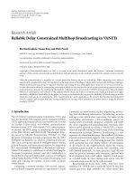
3.2. Systems with multiple receive antennas
For systems with two or more receive antennas, channel es-
timation can be performed at each receiver independently or
from more than one receiver jointly. The major advantage of
joint channel estimation is that accurate noise variance es-
timation becomes possible without inserting extra zeros or
extending the frame length.
Tx-1
Tx-2
h
1
h
2
g
1
g
2
Rx-1
Rx-2
Figure 2: Two-branch transmit diversity with two receive antennas.
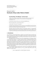
Take a synchronous 2 × 2 system as an example (see
Figure 2). Define H
1
, H
2
as in (5)andG
1
, G
2
as in (6), cor-
responding to h
1
, h
2
, g
1
, g
2
,respectively.If[a
1
, a
2
, , a
M
]is
transmitted through h
1
, h
2
,and[b
1
, b
2
, , b
M
]istransmit-
ted through g
1
, g
2
, the received signal at receivers 1 and 2 can
be expressed as
z
1
k
=
H
1
, G
1
a
k
b
k
+ n
1
k
, z
2
k
=
H
2
, G
2
a
k
b
k
+ n
2
k
,
(25)
where z
1
k
, z
2
k
, n
1
k
, n
2
k
are defined in the same manner as in
Section 2. Stacking z
1
k
, z
2
k
into a 2(N +L+1)-vector, we obtain
z
L
k
=
z
1
k
z
2
k
=
H
1
G
1
H
2
G
2
F
a
k
b
k
s
k
+
n
1
k
n
2
k
. (26)
Considering the correlation matrix of z
L
k
, it follows that
R
L
z
= E
z
L
k
z
L
k
H
=
FF
H
+ σ
2
I
2(N+L+1)
. (27)
Note that F is a 2(N+L+1)
×2N tall matrix, the noise variance
σ
2
can be estimated through the SVD of R
L
z
, by averaging the
least 2(L +1)eigenvaluesofR
L
z
.
4. EQUALIZATION
Once channel estimation has been carried out, equalization
can be performed in several ways. Take the 2
× 2 as a n exam-
ple, define s
k
= [a
T
k
, b
T
k
]
T
as before, it follows from (26) that
the information blocks a
k
and b
k
can be estimated by
min
s
k
z
L
k
− Fs
k
, (28)
either using the least-squares (LS) method, the zero-forcing
(ZF) equalizer, or through the maximum-likelihood (ML)
approach based on the Viterbi algorithm. More specifically, if
finite alphabet constraint is put on s
k
, then (28)canbesolved
using the Viterbi algorithm; if this constraint is relaxed, then
s
k
can be obtained through the LS or ZF equalizer. In the sim-
ulations, we choose to use the ZF equalizer.
For systems with two transmit antennas and one receiver,
it follows from (5), (6), and (7) that
z
k
= [H, G]s
k
+ n
k
, (29)
6 EURASIP Journal on Wireless Communications and Networking
and [H, G]is(N + L +1)× 2N. The necessary condition
for [H, G]tobeoffull-columnrankisN + L +1
≥ 2N,
that is, N
≤ L +1.HerewechooseN = L + 1 to maxi-
mize the spectral efficiency. This implies that the overall data
rate (in symbols/s/Hz) of the two-branch transmission sys-
tem with one receiver will be the same as that of the corre-
sponding single-transmitter and single-receiver system un-
der the same modulation scheme. While in the 2
× 2system,
F is 2(N + L +1)
× 2N,obviouslyN is no longer constrained
by L, and can be chosen as large as possible, as long as the
frame length is within the channel coherence time range and
the computational complexity is acceptable.
With the proposed dual-branch structured transmit de-
lay scheme, blind channel identification and signal detection
can be performed with the overall data rate much higher than
that of the corresponding SISO system. For a 2
× 2systemin
a slow time-varying environment, for example, blind chan-
nel identification and signal detection can be achieved with a
data rate (in symbols/s/Hz, excluding training symbols and
dummyzeros)of2N/(N + L + 1) times that of the corre-
sponding SIMO system under the same modulation scheme
and with no training symbols transmitted.
5. EXTENSION OF THE STRUCTURED TR ANSMIT
DELAY SCHEME TO GENERAL MIMO SYSTEMS
In this section, extension of the proposed structured trans-
mit delay scheme to gener al MIMO systems is discussed. We
start with the dual-branch transmission systems where the
two branches are either synchronous or asynchronous, with
unknown transmission delays, and then consider the exten-
sion to systems with multiple-(more than two) transmit an-
tennas.
5.1. Dual-branch transmitter with unknown initial
transmission delays
Assume that the maximum transmission delay is d symbol
intervals and the maximum multipath delay spread is L sym-
bol intervals, the channel impulse responses corresponding
to the two air links can be represented with two (L+d +1)
×1
vectors,
h
=
h
− d
1
, h
− d
1
+1
, , h(0), h(1), , h
L + d −d
1
,
g
=
g
−
d
2
, g
−
d
2
+1
, , g(0), g(1), , g
L + d −d
2
,
(30)
where 0
≤ d
1
, d
2
≤ d.
(i) Initial transmission delays are unknown, and the two
branches are synchronous (0
≤ d
1
= d
2
≤ d).
Define
a
k
=
⎡
⎢
⎣
a
k
(0), a
k
(1), , a
k
(N − 1), 0, ,0
L+d+1
⎤
⎥
⎦
,
b
k
=
⎡
⎢
⎣
0, b
k
(0), b
k
(1), , b
k
(N − 1), 0, ,0
L+d
⎤
⎥
⎦
.
(31)
Suppose that [
a
1
, a
2
, , a
M
] are transmitted from antenna
1 through channel h,and[
b
1
, b
2
, , b
M
] from antenna 2
through channel g,pleaserefertoFigure 1. For simplicity of
the notation, we consider the system with a single-receive an-
tenna. In this case, following our notations in Figure 1,we
have
x
k
(n) =
L+d
l=0
h
l − d
1
a
k
(n − l),
y
k
(n) =
L+d
l=0
g
l − d
2
b
k
(n − l − 1).
(32)
Define x
k
= [x
k
(0), x
k
(1), , x
k
(N + L + d)]
T
, y
k
= [y
k
(0),
y
k
(1), , y
k
(N +L+d)]
T
,andn
k
= [n
k
(0), n
k
(1), , n
k
(N +
L + d)]
T
.Definez
k
= x
k
+ y
k
+ n
k
, then it follows that
z
k
=
⎡
⎢
⎢
⎢
⎢
⎢
⎢
⎢
⎢
⎢
⎢
⎢
⎢
⎢
⎢
⎢
⎢
⎢
⎢
⎢
⎢
⎢
⎢
⎢
⎢
⎢
⎢
⎢
⎢
⎢
⎢
⎢
⎢
⎢
⎢
⎢
⎢
⎢
⎢
⎢
⎢
⎢
⎣
d
1
⎧
⎪
⎪
⎨
⎪
⎪
⎩
0
.
.
.
0
h(0)a
k
(0)
h(1)a
k
(0) + h(0)a
k
(1) + g(0)b
k
(0)
h(2)a
k
(0) + h(1)a
k
(1) + h(0)a
k
(2)
+g(1)b
k
(0) + g(0)b
k
(1)
.
.
.
h(L)a
k
(0) + ···+ h(0)a
k
(L)
+ g(L
− 1)b
k
(0) + ···+ g(0)b
k
(L − 1)
.
.
.
h(L)a
k
(N − 1) + g(L)b
k
(N − 2)
+g(L
− 1)b
k
(N − 1)
g(L)b
k
(N − 1)
d
− d
1
⎧
⎪
⎪
⎨
⎪
⎪
⎩
0
.
.
.
0
⎤
⎥
⎥
⎥
⎥
⎥
⎥
⎥
⎥
⎥
⎥
⎥
⎥
⎥
⎥
⎥
⎥
⎥
⎥
⎥
⎥
⎥
⎥
⎥
⎥
⎥
⎥
⎥
⎥
⎥
⎥
⎥
⎥
⎥
⎥
⎥
⎥
⎥
⎥
⎥
⎥
⎥
⎦
+ n
k
.
(33)
As can be seen from (31),
a
k
and b
k
are defined in the similar
manner as that in Section 2.Theonlydifference is that due
to the unknown delays, L + d + 1 zeros are inserted to each
block instead of L + 1 zeros as in the delay known case, in
order to ensure that there is no interblock interference. At
the same time, this design guarantees that in z
k
, there is an
interference-free item h(0)a
k
(0), which plays a critical role
in blind channel estimation, please refer to Section 3.Delay
estimation will be discussed later on.
(ii) Initial transmission delays are unknown, and the two
branches are asynchronous (0
≤ d
1
, d
2
≤ d, d
1
= d
2
).
Define
a
k
=
⎡
⎢
⎣
a
k
(0), a
k
(1), , a
k
(N − 1), 0, ,0
L+2d+1
⎤
⎥
⎦
,
b
k
=
⎡
⎢
⎣
0, ,0
d+1
, b
k
(0), b
k
(1), , b
k
(N − 1), 0, ,0
L+d
⎤
⎥
⎦
.
(34)
Tongtong Li et al. 7
Again, transmitting [a
1
, a
2
, , a
M
] from antenna 1 through
channel h, and transmitting [
b
1
, b
2
, , b
M
] from antenna 2
through channel g, it turns out that
x
k
(n) =
L+d
l=0
h
l − d
1
a
k
(n − l),
y
k
(n) =
L+d
l=0
g
l − d
2
b
k
(n − l − d − 1).
(35)
Define x
k
= [x
k
(0), x
k
(1), , x
k
(N + L +2d)]
T
, y
k
= [y
k
(0),
y
k
(1), , y
k
(N + L +2d)]
T
, n
k
= [n
k
(0), n
k
(1), , n
k
(N +
L +2d)]
T
, and again define
z
k
= x
k
+ y
k
+ n
k
, (36)
where
x
k
=
⎡
⎢
⎢
⎢
⎢
⎢
⎢
⎢
⎢
⎢
⎢
⎢
⎢
⎢
⎢
⎢
⎢
⎢
⎢
⎢
⎢
⎢
⎢
⎢
⎢
⎢
⎢
⎢
⎢
⎣
d
1
⎧
⎪
⎪
⎨
⎪
⎪
⎩
0
.
.
.
0
h(0)a
k
(0)
h(1)a
k
(0) + h(0)a
k
(1)
h(2)a
k
(0) + h(1)a
k
(1) + h(0)a
k
(2)
.
.
.
h(L)a
k
(0) + ···+ h(0)a
k
(L)
.
.
.
h(L)a
k
(N − 1)
2d
− d
1
+1
⎧
⎪
⎪
⎨
⎪
⎪
⎩
0
.
.
.
0
⎤
⎥
⎥
⎥
⎥
⎥
⎥
⎥
⎥
⎥
⎥
⎥
⎥
⎥
⎥
⎥
⎥
⎥
⎥
⎥
⎥
⎥
⎥
⎥
⎥
⎥
⎥
⎥
⎥
⎦
,
y
k
=
⎡
⎢
⎢
⎢
⎢
⎢
⎢
⎢
⎢
⎢
⎢
⎢
⎢
⎢
⎢
⎢
⎢
⎢
⎢
⎢
⎢
⎢
⎢
⎢
⎢
⎢
⎢
⎢
⎢
⎣
d + d
2
+1
⎧
⎪
⎪
⎨
⎪
⎪
⎩
0
.
.
.
0
g(0)b
k
(0)
g(1)b
k
(0) + g(0)b
k
(1)
g(2)b
k
(0) + g(1)b
k
(1) + g(0)b
k
(2)
.
.
.
g(L)b
k
(0) + ···+ g(0)b
k
(L)
.
.
.
g(L)b
k
(N − 1)
d
− d
2
⎧
⎪
⎪
⎨
⎪
⎪
⎩
0
.
.
.
0
⎤
⎥
⎥
⎥
⎥
⎥
⎥
⎥
⎥
⎥
⎥
⎥
⎥
⎥
⎥
⎥
⎥
⎥
⎥
⎥
⎥
⎥
⎥
⎥
⎥
⎥
⎥
⎥
⎥
⎦
.
(37)
An insight into the design in (34) is provided through
two extreme cases. First, consider the case where d
1
= d,
d
2
= 0. It turns out that
z
k
=
⎡
⎢
⎢
⎢
⎢
⎢
⎢
⎢
⎢
⎢
⎢
⎢
⎢
⎢
⎢
⎢
⎢
⎢
⎢
⎢
⎢
⎢
⎢
⎢
⎢
⎢
⎢
⎢
⎢
⎢
⎢
⎢
⎢
⎢
⎢
⎢
⎢
⎢
⎢
⎢
⎢
⎢
⎣
d
⎧
⎪
⎪
⎨
⎪
⎪
⎩
0
.
.
.
0
h(0)a
k
(0)
h(1)a
k
(0) + h(0)a
k
(1) + g(0)b
k
(0)
h(2)a
k
(0) + h(1)a
k
(1) + h(0)a
k
(2)
+g(1)b
k
(0) + g(0)b
k
(1)
.
.
.
h(L)a
k
(0) + ···+ h(0)a
k
(L)
+ g(L
− 1)b
k
(0) + ···+ g(0)b
k
(L − 1)
.
.
.
h(L)a
k
(N − 1) + g(L)b
k
(N − 2)
+g(L
− 1)b
k
(N − 1)
g(L)b
k
(N − 1)
d
⎧
⎪
⎪
⎨
⎪
⎪
⎩
0
.
.
.
0
⎤
⎥
⎥
⎥
⎥
⎥
⎥
⎥
⎥
⎥
⎥
⎥
⎥
⎥
⎥
⎥
⎥
⎥
⎥
⎥
⎥
⎥
⎥
⎥
⎥
⎥
⎥
⎥
⎥
⎥
⎥
⎥
⎥
⎥
⎥
⎥
⎥
⎥
⎥
⎥
⎥
⎥
⎦
+ n
k
.
(38)
Second, exchange the role in the previous example and
consider the case where d
1
= 0andd
2
= d, then we have
z
k
=
⎡
⎢
⎢
⎣
h(0)a
k
(0)
.
.
.
g(L)b
k
(N − 1)
⎤
⎥
⎥
⎦
+ n
k
. (39)
From the above two extreme cases, we can see that struc-
tured transmit delay is elaborately designed in ( 34 )toensure
that there is no interblock interference and that there is an
interference-free term to allow simple blind channel estima-
tion. At the receiver end, to retrieve the channel status in-
formation, we still rely on the covariance matrix R
z
. In the
absence of noise, the first d
1
rows of R
z
are all zeros. The
(d
1
+ 1)th row contains all the information needed to esti-
mate h, that is, [ ,
|h(0)|
2
, h(0)h(1)
∗
, , h(0)h(L)
∗
, ].
In the presence of noise, the first (d
1
+1)rowsofR
z
become
R
z
1:d
1
+1,:
=
⎡
⎢
⎢
⎢
⎢
⎢
⎢
⎢
⎢
⎣
σ
2
000 0 0 0 0 0··· 0
0 σ
2
0 ··· 0 0000··· 0
.
.
.
.
.
.
.
.
.
.
.
.
.
.
.
.
.
.
.
.
.
.
.
.
.
.
.
.
.
.
.
.
.
00
.
.
.
σ
2
0 0000··· 0
0
··· 00
X
0
2
+σ2 X
0
X
∗
1
··· X
0
X
∗
L
0 ··· 0
⎤
⎥
⎥
⎥
⎥
⎥
⎥
⎥
⎥
⎦
,
(40)
where
X
0
= h(0), X
1
= h(1), X
L
= h(L).
(41)
Clearly, delay d
1
can be estimated from the first (d
1
+1)
rows of R
z
since |h(0)|
2
+ σ
2
>σ
2
. Similarly, delay d
2
can
be estimated by exchanging the role of (34). Recall that M
8 EURASIP Journal on Wireless Communications and Networking
is the number of blocks in a frame, without loss of gener-
ality, assume that M is even. We transmit [
a
1
, a
2
, , a
M/2
, |
b
M/2+1
, b
M/2+2
, , b
M
] from antenna 1 through channel h,
and [
b
1
, b
2
, , b
M/2
, | a
M/2+1
, a
M/2+2
, , a
M
] from antenna
2 through channel g. After the transmission delays are esti-
mated, noise variance estimation and channel estimation for
systems with either one or more receive antenna(s) follow di-
rectly from our discussion in Section 3.
5.2. Extension to systems with more than two
transmit antennas
Extension to systems with multiple-(more than two) trans-
mit antennas is not unique. Here we illustrate one possibility
by taking a three-branch transmitter as an example. First, we
convert the input sequence into three parallel data streams
and partition each data stream into N-symbol blocks a
k
, b
k
,
c
k
. In the case when the system is synchronous and the tr ans-
mission delay is known (other cases can be extended simi-
larly), define
a
k
=
⎡
⎢
⎣
a
k
(0), a
k
(1), , a
k
(N − 1), 0, ,0
L+1
⎤
⎥
⎦
,
b
k
=
⎡
⎢
⎣
0, b
k
(0), b
k
(1), , b
k
(N − 1), 0, ,0
L
⎤
⎥
⎦
,
c
k
=
⎡
⎢
⎣
0, c
k
(0), c
k
(1), , c
k
(N − 1), 0, ,0
L
⎤
⎥
⎦
.
(42)
Assume that there are 2M blocks in a frame, transmit
a
1
, , a
M
, | b
M+1
,, , b
2M
,
b
1
, , b
M
, | a
M+1
,, , a
2M
,
c
1
, , c
M
, | c
M+1
,, , c
2M
,
(43)
from three antennas, through channels h
1
, h
2
, h
3
,respec-
tively. Again, our transmit delay structure here is designed
to avoid interblock interference and to ensure that there is an
interference-free item for simple blind channel estimation.
Channel h
1
can be estimated through the covariance ma-
trix of the received signal obtained from the first M blocks
in the frame, and channels h
2
and h
3
can be estimated from
the second half of the frame. Compared with the two-branch
case, the block size N needs to be kept small enough such
that a 2M-block interval is less than the channel coherence
time. In view of the computational complexity and the essen-
tial improvement on spectral efficiency, the number of trans-
mit antennas to be used in the system would be channel-and
application-dependent.
6. SIMULATION RESULTS
In this section, simulation results are provided to illustrate
the performance of the proposed approach. In the simula-
tion examples, each antenna transmits BPSK signals and the
channel impulse response between each transmitter-receiver
pair is generated randomly and independently. The channel
is assumed to be static within each frame consisting of M
blocks. Systems with different block sizes are tested. It will be
seen that a s the block size gets larger, we get more accurate
approximation of desired statistics, and hence obtain better
results.
In the simulation,
normalized channel estimation MSE
1
I
I
i=1
h
i
− h
i
2
h
i
2
,
(44)
where h
i
and
h
i
denote the estimated channel and the true
channel in the ith run, respectively. I is the total number
of Monte Carlo runs. At each receive antenna, SNR is de-
fined as the ratio between the total received signal power and
the noise power, and it is assumed that the receive antennas
have the same SNR level. For systems with a single-receive
antenna, we choose N
= L + 1, resulting in an overall data
rate of 1. For systems with two receive antennas, we choose
N
= 3(L + 1) so that the overall data rate is 1.5 times that
of the corresponding SISO system over the same bandwidth.
In all examples, the zero-forcing equalizer is used for signal
detection. As it is well known, blind equalization can only be
achieved up to an unknown constant phase and delay. In the
simulation, the phase ambiguity is resolved by adding one
pilot symbol for every M block at each transmit antenna. All
the simulation results are averaged over I
= 500 Monte Carlo
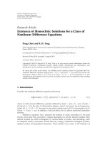
runs. In the following, three examples are considered.
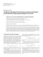
Example 1 (synchronous two-branch transmission with a single
receiver). The multipath channels are assumed to have 6 rays,
the amplitude of each ray is zero-mean complex Gaussian
with unit variance, the first ray has no initial delay, and the
delays for the remaining 5 rays are uniformly distributed over
[1, 5] symbol periods. Figure 3 shows the MSE of blind chan-
nel estimation both with and without noise variance estima-
tion, and resulted BER (with noise variance estimation only)
for various block sizes. It can be seen that (i) good noise vari-
ance estimation results in significantly more accurate chan-
nel estimation, (ii) wh en the number of blocks, M, increases,
better results are achieved as the time-averaged statistics ap-
proach their ensemble values, (iii) BER is not satisfying even
if the channel estimation is good, as there is only one-receive
antenna.
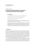
The performance of the proposed channel estimation al-
gorithm versus the relative power of the first tap has been
provided in Figure 4. In the simulation, the multipath chan-
nel is assumed to have 6 rays, each is complex Gaussian with
zero mean and variance 1/6. The results are averaged over
500 Monte Carlo runs where the channel is randomly gener-
ated for each run. These 500 channels are grouped into two
classes: (a) power of the first tap lower than the average tap
power, and (b) power of the first tap larger than the average
tap power. As expected, class (b) delivers better result.
Tongtong Li et al. 9
0
−5
−10
−15
−20
−25
MSE of channel estimation (dB)
0 5 10 15 20 25
SNR (dB)
M
= 40 without noise variance estimation
M
= 200 without noise variance estimation
M
= 500 without noise variance estimation
M
= 40 with noise variance estimation
M
= 200 with noise variance estimation
M
= 500 with noise variance estimation
(a)
10
0
10
−1
10
−2
10
−3
BER
0 5 10 15 20 25
SNR (dB)
M
= 40
M
= 200
M
= 500
Perfect channel
(b)
Figure 3: Example 1, synchronous two-branch transmission with a s ingle receiver, N = L+1, data rate = 1, (a) normalized channel estimation
MSE versus SNR, (b) BER versus SNR (with noise variance estimation).
5
0
−5
−10
−15
−20
−25
MSE of channel estimation
0 5 10 15 20 25
SNR (dB)
M
= 40, overall
M
= 200, overall
M
= 500, overall
M
= 40, power of the first tap lower than average power
M
= 200, power of the first tap lower than average power
M
= 500, power of the first tap lower than average power
M
= 40, power of the first tap higher than average power
M
= 200, power of the first tap higher than average power
M
= 500, power of the first tap higher than average power
Figure 4: Performance sensitivity of the proposed channel estima-
tion method to the relative power of the first tap.
Example 2 (synchronous two-branch transmission with two re-
ceivers). In this example, the channels have the same charac-
teristics as in Example 1, channel estimation is carried out at
each receive antenna independently with and without noise
variance estimation, and noise variance estimation is per-
formed as described in Section 3.2. It should be noted that
although it is possible to obtain good channel estimation re-
sults with one-receive antenna, two-receive antennas are nec-
essary to recover the original inputs when we are transmit-
ting at a higher data rate (1.5 times that of the corresponding
SISO system).
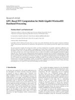
We also consider to improve the system performance
by combining the threaded layered space-time (TST) ar-
chitecture [17] with the proposed transmission scheme, as
shown in Figure 5. Here “SI” stands for spatial interleaver,
and “Int” for interleaver. Turbo encoder is chosen for for-
ward error control. At the receiver, hard decisions are made
on the equalizer outputs, and there is no iteration between
the receiver front end and the turbo decoder. The decod-
ing algorithm is chosen to be log-MAP [40]. The number
of decoding iterations is set to be 5, and no early termina-
tion scheme is applied. The rate of the turbo code is 1/2.
The block length is 6000. The generation matrix of the con-
stituent code is given by [1, (7)
octal
/(5)
octal
], where (7)
octal
and (5)
octal
are the feedback and feedforward polynomials
with memory length 2, respectively. After space-domain in-
terleaving and time-domain interleaving, the symbols trans-
mitted from each antenna will be independent with each
other and with the symbols transmitted from other antennas.
10 EURASIP Journal on Wireless Communications and Networking
Input bits
S/P
Encoder
Encoder
MAP
MAP
SI
Int.
Int.
a
k
b
k
Zero
padding
Zero
padding
¯
a
k
¯
b
k
Channel
h
Channel
g
x
k
y
k
+
n
k
z
k
Figure 5: Space-time diversity with the threaded layered space-time (TST) architecture.
−2
−4
−6
−8
−10
−12
−14
−16
−18
−20
MSE of channel estimation (dB)
0 5 10 15 20 25
SNR (dB)
M
= 40 without noise variance estimation
M
= 200 without noise variance estimation
M
= 500 without noise variance estimation
M
= 40 with noise variance estimation
M
= 200 with noise variance estimation
M
= 500 with noise variance estimation
(a)
10
0
10
−1
10
−2
10
−3
10
−4
10
−5
10
−6
BER
0 5 10 15 20 25
SNR (dB)
M
= 40, BPSK without turbo coding
M
= 200, BPSK without turbo coding
M
= 500, BPSK without turbo coding
M
= 20, QPSK with turbo coding
M
= 100, QPSK with turbo coding
M
= 250, QPSK with turbo coding
(b)
Figure 6: Example 2, synchronous two-branch transmission with two receivers, N = 3(L +1),datarate= 1.5, (a) normalized channel
estimation MSE versus SNR, (b) BER versus SNR (with noise variance estimation).
The proposed transmission scheme, therefore, can be directly
concatenated with the TST structure. From Figure 6,itcanbe
seen that the 2-by-2 systems can achieve much better BER at
a higher data rate. Significant improvement can be observed
when turbo coding and TST structure are employed. For fair
comparison, when turbo encoder is added, the system trans-
mits QPSK signals instead of BPSK signals, which are used
for the systems without turbo coding.
Example 3 (asynchronous two-branch transmission with two
receivers). In this example, system performance is tested in
two cases: (i) transmission delays are known, (ii) transmis-
sion delays are unknown. The channels are assumed to have
three rays, the initial delays are uniformly distributed over
[0, 2] symbols, the direct path amplitude is normalized to 1,
and the two successive paths have relative delays (with respect
to the first arrival) uniformly distributed over [1,5] sym-
bols with complex Gaussian amplitudes of zero mean and
standard deviation 0.3. That is, the maximum initial delay is
d
= 2, and the maximum multipath delay spread is L = 5. We
use the same turbo encoder as in Example 2.Ascanbeseen
from Figure 7, when the delays are unknown, for the first ar-
rival to be detected, the signal power of the first path should
be sufficiently large in comparison with the noise power. And
when SNR
≥ 10 dB, channel estimation with unknown de-
lays is as good as that with know n delays.
7. CONCLUSIONS
In this paper, a dual-branch transmission scheme that utilizes
guard intervals for blind channel estimation and equalization
is proposed. Unlike existing transmit diversity schemes, in
which each antenna transmits different versions of the same
signal, the proposed transmission scheme promises higher
data rate since each antenna transmits an independent data
stream. It is shown that with two-transmit antennas and one-
receive antenna, blind channel estimation and equalization
can be carried out based only on the second-order statis-
tics of symbol-rate sampled channel output. This can be
Tongtong Li et al. 11
5
0
−5
−10
−15
−20
−25
MSE of channel estimation (dB)
0 5 10 15 20 25
SNR (dB)
M
= 200, known delay
M
= 500, known delay
M
= 200, unknown delay
M
= 500, unknown delay
(a)
10
0
10
−1
10
−2
10
−3
10
−4
10
−5
10
−6
10
−7
BER
0 5 10 15 20 25
SNR (dB)
BPSK with M
= 200, delay known without turbo coding
BPSK with M
= 200, delay unknown without turbo coding
QPSK with M
= 100, delay known with turbo coding
QPSK with M
= 100, delay unknown with turbo coding
(b)
Figure 7: Example 3, asynchronous two-branch transmission with two receivers, N = 3(L+1), data rate = 1.5, with noise variance estimation,
(a) normalized channel estimation MSE versus SNR, (b) BER versus SNR when M
= 200.
regarded as a counterpart of [6] which exploits receive diver-
sity. The proposed approach involves no preequalization and
has no limitations on channel-zero locations. Higher system
capacity can be achieved with better perform ance when more
than one-receive antennas are available. It is also shown that
in combination with the TST structure and turbo coding, sig-
nificant improvement can be observed in the overall system
performance.
ACKNOWLEDGMENTS
This paper is supported in part by MSU IRGP 91-4005 and
NSF Grants CCR-0196364 and ECS-0121469.
REFERENCES
[1] G. B. Giannakis and S. D. Halford, “Asymptotically optimal
blind fractionally spaced channel estimation and performance
analysis,” IEEE Transactions on Signal Processing, vol. 45, no. 7,
pp. 1815–1830, 1997.
[2] H. H. Zeng and L. Tong, “Blind channel estimation using the
second-order statistics: algorithms,” IEEE Transactions on Sig-
nal Processing, vol. 45, no. 8, pp. 1919–1930, 1997.
[3] H. H. Zeng and L. Tong, “Blind channel estimation using the
second-order statistics: asymptotic performance and limita-
tions,” IEEE Transactions on Signal Processing, vol. 45, no. 8,
pp. 2060–2071, 1997.
[4] L. L. Mazet, P. Ciblat, and P. Loubaton, “Fractionally spaced
blind equalization: CMA versus second order based methods,”
in Proceedings of the 2nd IEEE Workshop on Sig nal Processing
Advances in Wireless Communications (SPAWC ’99), pp. 231–
234, Annapolis, Md, USA, May 1999.
[5] E. Moulines, P. Duhamel, J F. Cardoso, and S. Mayrargue,
“Subspace methods for the blind identification of multichan-
nel FIR filters,” IEEE Transactions on Signal Processing, vol. 43,
no. 2, pp. 516–525, 1995.
[6] L. Tong, G. Xu, and T. Kailath, “Blind identification and equal-
ization based on second-order statistics: a time domain ap-
proach,” IEEE Transactions on Information Theory, vol. 40,
no. 2, pp. 340–349, 1994.
[7] G. J. Foschini and M. J. Gans, “On limits of wireless commu-
nications in a fading environment when using multiple an-
tennas,” Wireless Personal Communications,vol.6,no.3,pp.
311–335, 1998.
[8] E. Telatar, “Capacity of multi-antenna Gaussian channels,” Eu-
ropean Transactions on Telecommunications,vol.10,no.6,pp.
585–595, 1999.
[9] S. M. Alamouti, “A simple transmit diversity technique for
wireless communications,” IEEE Journal on Selected Areas in
Communications, vol. 16, no. 8, pp. 1451–1458, 1998.
[10] G. J. Foschini, “Layered space-time architecture for wireless
communication in a fading environment when using multi-
element antennas,” Bell Labs Technical Journal, vol. 1, no. 2,
pp. 41–59, 1996.
[11] V. Tarokh, N. Seshadri, and A. R. Calderbank, “Space-time
codes for high data rate wireless communication: perfor mance
criterion and code construction,” IEEE Transactions on Infor-
mation Theory, vol. 44, no. 2, pp. 744–765, 1998.
[12] V. Tarokh, H. Jafarkhani, and A. R. Calderbank, “Space-time
block codes from orthogonal designs,” IEEE Transactions on
Information Theory, vol. 45, no. 5, pp. 1456–1467, 1999.
[13] N. Seshadri and J. H. Winters, “Two signaling schemes for im-
proving the error performance of frequency-division-duplex
(FDD) transmission systems using t ransmitter antenna diver-
sity,” in Proceedings of the 43rd IEEE Vehicular Technology Con-
ference(VTC’93), pp. 508–511, Secaucus, NJ, USA, May 1993.
12 EURASIP Journal on Wireless Communications and Networking
[14] A. Wittneben, “A new bandwidth efficient transmit antenna
modulation diversity scheme for linear digital modulation,” in
Proceedings of IEEE International Conference on Communica-
tions (ICC ’93), vol. 3, pp. 1630–1634, Geneva, Switzerland,
May 1993.
[15] J. H. Winters, “The diversity gain of transmit diversity in wire-
less systems w ith Rayleigh fading,” IEEE Transactions on Vehic-
ular Technology, vol. 47, no. 1, pp. 119–123, 1998.
[16] B. Vucetic and J. Yuan, Space-Time Coding,JohnWiley&Sons,
New York, NY, USA, 2003.
[17] H. El Gamal and A. R. Hammons Jr., “A new approach to lay-
ered space-time coding and signal processing,” IEEE Trans-
actions on Information Theory, vol. 47, no. 6, pp. 2321–2334,
2001.
[18] P. W. Wolniansky, G. J. Foschini, G. D. Golden, and R. A.
Valenzuela, “V-BLAST: an architecture for realizing very high
data rates over the rich-scattering wireless channel,” in Pro-
ceedings of URSI International Symposium on Signals, Sys-
tems, and Electronics (ISSSE ’98), pp. 295–300, Pisa, Italy,
September-October 1998.
[19] D. Gore, S. Sandhu, and A. J. Paulraj, “Blind channel identi-
fication and projection receiver determination for multicode
and multirate situations in DS-CDMA systems,” in Proceed-
ings of IEEE International Conference on Communications (ICC
’02), vol. 3, pp. 1949–1953, New York, NY, USA, April-May
2002.
[20] E. Lindskog and A. Paulraj, “A transmit diversity scheme
for channels with intersymbol interference,” in Proceedings of
IEEE International Conference on Communications (ICC ’00),
vol. 1, pp. 307–311, New Orleans, La, USA, June 2000.
[21] W J. Choi and J. M. Cioffi, “Space-time block codes over
frequency selective Rayleigh fading channels,” in Proceedings
of the 50th IEEE Vehicular Technology Conference (VTC ’99),
vol. 5, pp. 2541–2545, Amsterdam, The Netherlands, Septem-
ber 1999.
[22] S. Zhou and G. B. Giannakis, “Single-carrier space-time block-
coded transmissions over frequency-selective fading chan-
nels,” IEEE Transactions on Information Theory, vol. 49, no. 1,
pp. 164–179, 2003.
[23] Y. Ding, T. N. Davidson, and K. M. Wong, “Orthogonal block
code design for frequency-selective multiple antenna chan-
nels,” in Proceedings of IEEE Sensor Array and Multichannel
Signal Processing Workshop, pp. 279–283, Barcelona, Spain,
July 2004.
[24] A. L. Swindlehurst and G. Leus, “Blind and semi-blind equal-
ization for generalized space-time block codes,” IEEE Transac-
tions on Signal Processing, vol. 50, no. 10, pp. 2489–2498, 2002.
[25] N. Ammar and Z. Ding, “On blind channel identifiability un-
der space-time coded transmission,” in Proceedings of the 36th
Asilomar Conference on Signals, Systems and Computers, vol. 1,
pp. 664–668, Pacific Groove, Calif, USA, November 2002.
[26] N. Ammar and Z. Ding, “Frequency selective channel esti-
mation in time-reversed space-time coding,” in Proceedings
of IEEE Wireless Communications and Networking Conference
(WCNC ’04), vol. 3, pp. 1838–1843, Atlanta, Ga, USA, March
2004.
[27] J. Choi, “Equalization and semi-blind channel estimation for
space-time block coded signals over a frequency-selective fad-
ing channel,” IEEE Transactions on Signal Processing, vol. 52,
no. 3, pp. 774–785, 2004.
[28] S. Zhou, B. Muquet, and G. B. Giannakis, “Subspace-based
(semi-) blind channel estimation for block precoded space-
time OFDM,” IEEE Transactions on Signal Processing, vol. 50,
no. 5, pp. 1215–1228, 2002.
[29] C. B. Papadias, “Unsupervised receiver processing techniques
for linear space-time equalization of wideband multiple in-
put/multiple output channels,” IEEE Transactions on Signal
Processing, vol. 52, no. 2, pp. 472–482, 2004.
[30] H. Li, X. Lu, and G. B. Giannakis, “Capon multiuser receiver
for CDMA systems with space-time coding ,” IEEE Transac-
tions on Signal Processing, vol. 50, no. 5, pp. 1193–1204, 2002.
[31] S. Shahbazpanahi, A. B. Gershman, and G. B. Giannakis,
“Semiblind multiuser MIMO channel estimation using capon
and MUSIC techniques,” IEEE Transactions on Sig nal Process-
ing, vol. 54, no. 9, pp. 3581–3591, 2006.
[32] W K. Ma, B N. Vo, T. N. Davidson, and P C. Ching, “Blind
ML detection of orthogonal space-time block codes: effi-
cient high-performance implementations,” IEEE Transactions
on Signal Processing, vol. 54, no. 2, pp. 738–751, 2006.
[33] S. Shahbazpanahi, A. B. Gershman, and J. H. Manton,
“Closed-form blind MIMO channel estimation for orthogonal
space-time block codes,” IEEE Transactions on Signal Process-
ing, vol. 53, no. 12, pp. 4506–4517, 2005.
[34] S. Shahbazpanahi, A. B. Gershman, and J. H. Manton, “A lin-
ear precoding approach to resolve ambiguity of blind decoding
of orthogonal space-time block codes in slowly fading chan-
nels,” in Proceedings of the 5th IEEE Workshop on Signal Pro-
cessing Advances in Wireless Communications (SPAWC ’04),pp.
228–232, Lisbon, Portugal, July 2004.
[35] R. V. Nee and R. Prasad, OFDM for Wireless Multimedia Com-
munications,ArtechHousePublishers,Norwood,Mass,USA,
2000.
[36] S. Zhou, G. B. Giannakis, and C. L. Martret, “Chip-interleaved
block-spread code division multiple access,” IEEE Transactions
on Communications, vol. 50, no. 2, pp. 235–248, 2002.
[37] E. Serpedin and G. B. Giannakis, “Blind channel identification
and equalization w ith modulation-induced cyclostationarity,”
IEEE Transactions on Signal Processing, vol. 46, no. 7, pp. 1930–
1944, 1998.
[38] A. Scaglione, G. B. Giannakis, and S. Barbarossa, “Redun-
dant filterbank precoders and equalizers—part I: unification
and optimal designs,” IEEE Transactions on Signal Processing,
vol. 47, no. 7, pp. 1988–2006, 1999.
[39] A. Scaglione, G. B. Giannakis, and S. B arbarossa, “Redundant
filterbank precoders and equalizers—part II: blind channel
estimation, synchronization, and direct equalization,” IEEE
Transactions on Signal Processing, vol. 47, no. 7, pp. 2007–2022,
1999.
[40] J. P. Woodard and L. Hanzo, “Comparative study of turbo de-
coding techniques: an overview,” IEEE Transactions on Vehicu-
lar Technology, vol. 49, no. 6, pp. 2208–2233, 2000.