Báo cáo hóa học: " Research Article Throughput Analysis of Large Wireless Networks with Regular Topologies" pot
Bạn đang xem bản rút gọn của tài liệu. Xem và tải ngay bản đầy đủ của tài liệu tại đây (943.88 KB, 11 trang )
Hindawi Publishing Corporation
EURASIP Journal on Wireless Communications and Networking
Volume 2007, Article ID 26760, 11 pages
doi:10.1155/2007/26760
Research Article
Throughput Analysis of Large Wireless Networks with
Regular Topologies
Kezhu Hong and Yingbo Hua
Department of Electrical Engineering, University of California, Riverside, CA 92521, USA
Received 2 September 2006; Revised 12 December 2006; Accepted 23 February 2007
Recommended by Weihua Zhuang
The throughput of large wireless networks with regular topologies is analyzed under two medium-access control schemes: syn-
chronous array method (SAM) and slotted ALOHA. The regular topologies considered are square, hexagon, and triangle. Both
nonfading channels and Rayleigh fading channels are examined. Furthermore, both omnidirectional antennas and directional an-
tennas are considered. Our analysis shows that the SAM leads to a much higher network throughput than the slotted ALOHA. The
network throughput in this paper is measured in either bits-hops per second per Hertz per node or bits-meters per second per
Hertz per node. The exact connection between the two measures is shown for each topology. With these two fundamental units,
the network throughput shown in this paper can serve as a reliable benchmark for future works on network throughput of large
networks.
Copyright © 2007 K. Hong and Y. Hua. This is an open access article distributed under the Creative Commons Attribution
License, which permits unrestricted use, distribution, and reproduction in any medium, provided the original work is properly
cited.
1. INTRODUCTION
The maximum achievable throughput of a large wireless net-
work has been a topic of great interest. A large wireless net-
work can take many possible forms in practice, which in-
clude large sensor networks, large ad hoc networks, and large
mesh networks. A large mesh network may consist of a large
number of wireless transceivers located (or approximately lo-
cated) on a regular grid. Such a mesh network may serve as
a virtual backbone for other mobile wireless clients. Since all
nodes in the mesh network share the same w ireless medium,
the maximum network spectr al efficiency (i.e., the maxi-
mum achievable network throughput) is of paramount im-
portance. This is particularly true if the network is operating
under heavy loads.
Until the recent works [1, 2], most of the research ac-
tivities on maximum achievable throughput (i.e., capacity)
of large wireless networks focus on scaling laws, for exam-
ple, [3–5]. A capacity scaling law typically yields an upper
bound on the maximum achievable throughput of the net-
work, and the bound is often quite loose especially when
appliedtoagivennetworktopology.Asarguedin[1, 2],
an exact and achievable throughput of a large network with
a given topology is also of practical and theoretical impor-
tance. The throughput of a large mesh network is such an ex-
ample. However, the throughput of a large network critically
depends on medium-access control scheme.
In [2], a medium-access control scheme called syn-
chronous array method (SAM) is proposed, and the net-
work throughput of the SAM is analyzed under the nonfad-
ing channel condition and the square network topology. The
essence of the SAM is that all packet transmissions in the
network are orthogonal in time and/or frequency and the
distance between any two adjacent t ransceivers is optimized
to maximize the network spectral efficiency. It is shown in
[2] that the throughput of the SAM is about 2–4 times the
throughput of a well-known random-access scheme called
slotted ALOHA [6].
In this paper, we present a further analysis of the SAM. In
this analysis, we consider not only the square topology, but
also the hexagonal and triangular topologies. We also con-
sider the Rayleigh fading channels. Both omnidirectional an-
tennas and directional antennas are treated in the analysis.
By network throughput we imply the maximum per-
node uniform throughput under full load. By full load we
imply that whenever a node is scheduled to transmit a packet
in a given direction, there is at least one such packet available
at the node.
To evaluate the network throughput, we will use two fun-
damental units: bits-hops/s/Hz/node and bits-meters/s/Hz/
2 EURASIP Journal on Wireless Communications and Networking
node. The unit bits-hops/s/Hz/node measures the number
of bits each node can transmit to its neighboring node
in a given direction p er second per Hertz. The unit bits-
meters/s/Hz/node measures the number of bits transported
over one-meter distance in an arbitrary direction (between
source and destination) from each node per second p er
Hertz. The connection between the two units depends on
the network topology, which will be shown under each of the
three topologies to be considered.
A throughput analysis of the slotted ALOHA is shown
in [ 1] where the throughput is expressed in packets/s/node.
Although commonly used, this unit is not as fundamental
as bits-hops/s/Hz/node or bits-meters/s/Hz/node as the lat-
ter takes into account the spectral efficiency of each packet
while the former does not. It will be seen that the spectral
efficiency of each packet can also be used to maximize the
network throughput. We believe that a network throughput
in bits-hops/s/Hz/node or bits-meters/s/Hz/node can serve
as a more reliable benchmark than a network throughput in
packets/s/node.
Note that according to Shannon’s theory, the maximal
spectral efficiency, that is, bits/s/Hz, that a packet can carry
has the expression log
2
(1 + η), where η is the signal-to-
interference-and-noise-ratio (SINR) threshold. When the ac-
tual SINR is larger than η, the packet is not detectible. When
the actual SINR is less than η, the packet is detectible pro-
vided that the coding is perfect and the packet length is suffi-
ciently long. By packet detection threshold we will refer to η.
A good review of other existing works on throughput
analysis of large networks with regular topologies is available
in [1], which we will not repeat.
The rest of this paper is organized as follows. In Section 2,
we analyze the network throughput under SAM and non-
fading channels for each of the three topologies: square,
hexagon, and triangle. Also shown is the connection be-
tween bits-hops/s/Hz/node and bits-meters/s/Hz/node for
each topology. The average source-destination (end-to-end)
delay for each topology is also presented. In Section 3,we
show the network throughput under SAM and fading chan-
nels for all three topologies. In Section 4, we present the net-
work throughput under slotted ALOHA and fading channels
for all three topologies. (For convenience, slotted ALOHA
will also be referred to as ALOHA. The network through-
put under ALOHA and nonfading channels is discussed in
[2] and will not be addressed in this paper.) A comparison
between SAM and ALOHA is summarized in Section 5.
2. NETWORK THROUGHPUT UNDER SAM AND
NONFADING CHANNELS
The synchronous array method (SAM) schedules packet
transmissions synchronously between arrays of nodes as
summarized next. The network is partitioned into inter-
leaved subsets (arrays) of nodes. During each time slot, a
subset of nodes with a predetermined spacing is scheduled to
transmit its packets towards its neighboring subset of nodes.
Depending on the spacing of each subset of nodes, it takes
several time slots for each node in the network to transmit
a packet to its neighbor in a given direction. Depending on
qd
sq
pd
sq
pd
sq
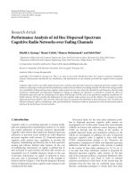
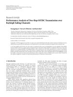
Figure 1: A network on the square grid with the spacing d
sq
me-
ters between two adjacent nodes. Under the SAM, data packets
are transmitted from the black nodes to their neighboring gray
nodes during a time slot. The vertical spacing between two active
transceivers is pd
sq
meters, and the horizontal spacing between two
active transceivers is qd
sq
meters. The offset between two adjacent
columns of active transceivers is
p/2d
sq
.
the network topology and the desired destination of a packet,
there are several directions to which the packet can be trans-
mitted. For each direction, the above process is repeated. The
time slots referred to above can be replaced by frequency slots
without affecting the network spectral efficiency. More de-
tails of the SAM will be revealed as we analyze the network
throughput for three regular topologies.
2.1. A network with square topology
Although partially presented in [2], this subsection is useful
for completeness of this paper. A network on square grid is il-
lustrated in Figure 1 whereasubsetofnodesisrepresentedby
the black nodes and its neighboring subset of nodes is repre-
sented by the gray nodes. During a time slot, the black nodes
are the transmitting nodes, and the gray nodes are the receiv-
ing nodes. The sparseness (spacing) of the subset is deter-
mined by pd
sq
and qd
sq
,wherep and q are integers a nd d
sq
is
the distance between two adjacent nodes. (The notation
p
denotes the largest integer less than p.) Both the sparseness
and the geometry of each subset affect the network through-
put. The geometry shown in Figure 1 is expected to be ideal
as the distance between any two pairs of transceivers is max-
imum for any given p and q.
For a different time slot, the location of the above-
described two subsets of nodes is shifted left, right, up, or
down. For every pq time slots, each of the nodes in the net-
work has one chance to transmit a packet to its neighbor in
a given direction. With the square topology, there are four
possible directions for a packet to be transmitted from each
node. The above process is repeated for each of the four di-
rections.
K. Hong and Y. Hua 3
To evaluate the network throughput, we first consider the
signal-to-interference-and-noise ratio (SINR) at each receiv-
ing node during a time slot:
SINR
=
P
T
/d
n
0
σ
2
+
i∈S
sub
P
T
/d
n
i
=
1
1/ SNR
0
+δ
SAM,sq
,(1)
where SNR
0
= P
T
/σ
2
d
n
0
, P
T
is the transmitted power from
each transmitting node, σ
2
is the noise variance, d
0
is the dis-
tance between a receiver and its desired transmitter (d
0
= d
sq
for the square topology), d
i
is the distance between the re-
ceiver and the ith interfering transmitters, n is the path loss
exponent, and δ
SAM,sq
=
i∈S
sub
d
n
0
/d
n
i
is referred to as the
interference factor for the square grid, S
sub
is the set of al l
interfering nodes.
In this paper, we consider a virtually infinite network.
When the network is finite, the throughput shown in this pa-
per is equivalent to a lower bound on the actual achievable
throughput. The numerical results shown later are all based
on the throughput of a center node in a network of about
200
× 200 nodes. The center node receives the largest inter-
ference, and hence governs a lower bound of the achievable
(per node) network throughput.
If a directional antenna is used on each node, there is a
power attenuation factor ξ between a receiver and a t rans-
mitter, which is defined as follows. ξ
= 1 if the transmitter
and the receiver are pointing to each other. ξ
= ( < 1) if
the transmitter is pointing to the receiver but the receiver is
not pointing to the transmitter (or if the receiver is pointing
to the transmitter but the transmitter is not pointing to the
receiver). ξ
=
2
if none of the transmitter and the receiver
is pointing to the other. In this case, the interference factor
becomes δ
SAM,sq
=
i
(d
0
/d
i
)
n
ξ
i
,whereξ
i
may be 1, ,or
2
depending on the relative orientation of the interferer.
When P
T
is sufficiently large, SINR becomes satura ted at
its upper bound 1/δ
SAM,sq
. For the case of nonfading chan-
nels, we will only consider the saturated SINR and the corre-
sponding network throughput.
We consider all interferences to be desired signals for
other nodes. Since the best encoded waveform is Gaussian
according to Shannon theory, it is reasonable to assume that
the interferences are all Gaussian. Assuming that the noise
and the interferences are all Gaussian and the network is (vir-
tually) infinite, the network capacity in bits-hops/s/Hz/node
is therefore
c
SAM,sq
=
1
G
sq
log
2
1+
1
δ
SAM,sq
,(2)
where G
sq
= pq is the number of time slots needed for each
of the nodes in the network to transmit once to its neigh-
boring node in a given direction on the square grid. Note
that c
SAM,sq
is an upper bound of the network capacity and is
achievable when P
T
is large. Here, each node is assumed to
have a single antenna.
Based on the geometry of the subset of nodes as shown
in Figure 1, one can verify that for p>1,
δ
SAM,sq
= δ
sq,1
+ δ
sq,2
+ δ
sq,3
+ δ
sq,4
+ δ
sq,5
,(3)
Table 1: The (p, q)-optimal network throughput in bits-hops/s/
Hz/node of a network on the square grid under the SAM and non-
fading channels.
c
∗
SAM,sq
,(p, q)
∗
= 1 = 0.1 = 0.01
n = 3 0.2166, (2, 3) 1.7914, (1, 2) 2.1668, (1, 2)
n
= 4 0.4208, (2, 3) 2.3780, (1, 2) 3.0442, (1, 2)
n
= 5 0.6210, (2, 3) 2.7425, (1, 2) 3.8689, (1, 2)
where
δ
sq,1
=
2
+
∞
i=0
+
∞
j=−∞
1
g=0
(2i +1)q +(−1)
g
2
+
pj−
p
2
2
−n/2
,
δ
sq,2
=
2
+
∞
i=0
+
∞
j=−∞
2(i +1)q − 1
2
+(pj)
2
−n/2
,
δ
sq,3
=
2
+
∞
i=0
j/=0
2(i +1)q +1
2
+(pj)
2
−n/2
,
δ
sq,4
=
+∞
i=0
2(i +1)q +1
2
−n/2
,
δ
sq,5
=
2
+
∞
j=1
1+(pj)
2
−n/2
.
(4)
Referring to Figure 1, one can verify that δ
sq,1
corresponds
to all the interferences from the transmitters located on the
first column, third column, fifth column, and so on, to the
left and right of each desired pair of transmitter and receiver;
δ
sq,2
corresponds to all the interferences from the transmit-
ters located on the second column, fourth column, and so on,
to the right of each desired pair of transmitter and receiver;
δ
sq,3
corresponds to all the interferences from the transmit-
ters located on the second column, fourth column, and so on,
to the left (except those in the line of sight) of each desired
pair of transmitter and receiver; δ
sq,4
corresponds to all the
interferences from the transmitters to the left and in the line
of sight of each desired pair of transmitter and receiver; and
δ
sq,5
is the interference from all the transmitters in the same
columnofeachdesiredpairoftransmitterandreceiver.
For p
= 1, one can similarly verify that
δ
SAM,sq
=
2
+
∞
i=0
+
∞
j=−∞
(i +1)q − 1
2
+(pj)
2
−n/2
+
2
+
∞
i=0
j/=0
(i +1)q +1
2
+(pj)
2
−n/2
+
+∞
i=0
(i +1)q +1
2
−n/2
+2
2
+
∞
j=1
1+( pj)
2
−n/2
.
(5)
For each given pair of n and
, the throughput c
SAM,sq
can be optimized over (p, q). Given in Table 1 are samples of
the (p, q)-optimal c
SAM,sq
(denoted by c
∗
SAM,sq
) and the corre-
sponding optimal (p, q)(denotedby(p, q)
∗
).
4 EURASIP Journal on Wireless Communications and Networking
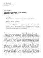
qd
hex
√
3pd
hex
Figure 2: A network on the hexagonal grid with the spacing d
hex
meters between two adjacent nodes. Under the SAM, data pack-
ets are transmitted from the black nodes to their neighboring gray
nodes during a time slot. The horizontal spacing between two ac-
tive transceivers is qd
hex
, and the vertical spacing between two active
transceivers is
√
3pd
hex
.
Table 2: The (p, q)-optimal network throughput in bits-hops/s/
Hz/node of a network on the hexagonal grid under the SAM and
nonfading channels.
c
∗
SAM,hex
,(p, q)
∗
= 1 = 0.1 = 0.01
n = 3 0.2794, (1, 3) 2.1297, (1, 1.5) 2.7976, (1, 1.5)
n
= 4 0.5430, (1, 3) 2.5813, (1, 1.5) 3.8645, (1, 1.5)
n
= 5 0.8040, (1, 3) 2.7474, (1, 1.5) 4.8132, (1, 1.5)
2.2. A network with hexagonal topology
Following the same idea shown previously, we now consider
a network on the hexagonal g rid as illustrated in Figure 2
where a subset of transmission pairs during a time slot is
denoted by the black and gray nodes. The vertical spacing
between adjacent transmission pairs is denoted by
√
3pd
hex
,
and the horizontal spacing between adjacent transmission
pairs is qd
hex
.Here,p takes all natural integers. But q can
be either q
= 3m or q = 3m − 1.5, where m is any natural
integer.
With the hexagonal topology, each node has three pos-
sible directions for a packet transmission. In order for each
node in the network to have one chance to transmit a packet
to its neighbor in one of its three directions, we need G
hex
=
2p(2q/3) time slots if q = 3m or G
hex
= 2p[2(q −1.5)/3+1]
time slots if q
= 3m − 1.5. Then, the network throughput in
bits-hops/s/Hz/node in one of three directions is given by
c
SAM,hex
=
1
G
hex
log
2
1+
1
δ
SAM,hex
,(6)
where δ
SAM,hex
is the interference factor for the hexagonal
topology. Following the geometry of the subset of nodes
shown in Figure 2, one can verify that if q
= 3m and p>1,
then
δ
SAM,hex
=
2
+
∞
i=0
+
∞
j=−∞
1
g=0
×
(2i+1)q+(−1)
g
2
+
√
3pj−
p
2
√
3
2
−n/2
+
2
+
∞
i=0
+
∞
j=−∞
2(i +1)q − 1
2
+
√
3pj
2
−n/2
+
2
+
∞
i=0
j/=0
2(i +1)q +1
2
+
√
3pj
2
−n/2
+
+∞
i=0
2(i +1)q +1
2
−n/2
+2
2
+
∞
j=1
1+
√
3pj
2
−n/2
(7)
and if q
= 3m and p = 1, then
δ
SAM,hex
=
2
+
∞
i=0
+
∞
j=−∞
(i +1)q − 1
2
+
√
3pj
2
−n/2
+
2
+
∞
i=0
j/=0
(i +1)q +1
2
+
√
3pj
2
−n/2
+
+∞
i=0
(i +1)q +1
2
−n/2
+2
2
+
∞
j=1
1+
√
3pj
2
−n/2
.
(8)
Furthermore, if q
= 3m − 1.5, then
δ
SAM,hex
=
2
+
∞
i=0
+
∞
j=−∞
(2i+1)q−1
2
+
√
3pj−
1
2
+
p
2
√
3
2
−n/2
+
2
+
∞
i=0
+
∞
j=−∞
(2i+1)q+1
2
+
√
3pj−
1
2
+
p
2
√
3
2
−n/2
+
2
+
∞
i=0
+
∞
j=−∞
2(i +1)q − 1
2
+
√
3pj
2
−n/2
+
2
+
∞
i=0
j/=0
2(i +1)q +1
2
+
√
3pj
2
−n/2
+
+∞
i=0
2(i +1)q +1
2
−n/2
+2
2
+
∞
j=1
1+
√
3pj
2
−n/2
.
(9)
Shown in Table 2 are samples of the (p, q)-optimal c
SAM,hex
and the corresponding optimal (p, q).
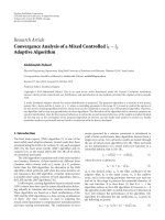
2.3. A network with triangle topology
A network on the triangle grid is shown in Figure 3 where
a subset of transmission pairs during a time slot is marked
K. Hong and Y. Hua 5
qd
tri
√
3pd
tri
Figure 3: A network on the triangular grid with the spacing d
tri
meters between two adjacent nodes. Under the SAM, data pack-
ets are transmitted from the black nodes to their neighboring gray
nodes during a time slot. The horizontal spacing between two ac-
tive transceivers is qd
tri
and the vertical spacing between two active
transceivers is
√
3pd
tri
.
Table 3: The (p, q)-optimal throughput in bits-hops/s/Hz/node of
a network on the triangular grid under the SAM and nonfading
channels.
c
∗
SAM,tri
,(p, q)
∗
= 1 = 0.1 = 0.01
n = 3 0.1863, (1, 3) 1.4198, (1, 1.5) 1.8651, (1, 1.5)
n
= 4 0.3620, (1, 3) 1.7209, (1, 1.5) 2.5763, (1, 1.5)
n
= 5 0.5360, (1, 3) 1.8316, (1, 1.5) 3.2088, (1, 1.5)
by black and gray nodes. The vertical spacing of transmis-
sion pairs is
√
3pd
tri
, and the horizontal spacing is qd
tri
.
Here, p takes any natural integers, but q can be either m or
m
− 0.5, where m is a natural integer. The number of time
slots required for all nodes in the network to transmit once
in one of six possible directions is G
tri
= 2pq if q = m,or
G
tri
= p[2(q − 0.5) + 1] if q = m − 0.5. The capacity in bits-
hops/s/Hz/node is therefore
c
SAM,tri
=
1
G
tri
log
2
1+
1
δ
SAM,tri
, (10)
where δ
SAM,tri
is the interference factor for the triangular
topology.
One can verify that if q
= 1, 2, 3 and p = 2, 3, 4 ,
then
δ
SAM,tri
=
2
+
∞
i=0
+
∞
j=−∞
1
g=0
(2i+1)q+(−1)
g
2
+
√
3pj−
p
2
√
3
2
−n/2
+
2
+
∞
i=0
+
∞
j=−∞
2(i +1)q − 1
2
+
√
3pj
2
−n/2
+
2
+
∞
i=0
j/=0
2(i +1)q +1
2
+
√
3pj
2
−n/2
+
+∞
i=0
2(i +1)q +1
2
−n/2
+2
2
+
∞
j=1
1+
√
3pj
2
−n/2
.
(11)
If q
= 1, 2, 3 and p = 1, then
δ
SAM,tri
=
2
+
∞
i=0
+
∞
j=−∞
(i +1)q − 1
2
+
√
3pj
2
−n/2
+
2
+
∞
i=0
j/=0
(i +1)q +1
2
+
√
3pj
2
−n/2
+
+∞
i=0
(i+1)q+1
2
−n/2
+2
2
+
∞
j=1
1+
√
3pj
2
−n/2
.
(12)
If q
= 0.5, 1.5, 2.5 and p = 1, 2, 3 , then
δ
SAM,tri
(n)
=
2
+
∞
i=0
+
∞
j=−∞
(2i+1)q−1
2
+
√
3pj−
1
2
+
p
2
√
3
2
−n/2
+
2
+
∞
i=0
+
∞
j=−∞
(2i+1)q+1
2
+
√
3pj−
1
2
+
p
2
√
3
2
−n/2
+
2
+
∞
i=0
+
∞
j=−∞
2(i +1)q − 1
2
+
√
3pj
2
−n/2
+
2
+
∞
i=0
j/=0
2(i +1)q +1
2
+
√
3pj
2
−n/2
+
+∞
i=0
2(i +1)q +1
2
−n/2
+2
2
+
∞
j=1
1+
√
3pj
2
−n/2
.
(13)
We see that δ
SAM,tri
(n)andδ
SAM,hex
(n) have a similar struc-
ture. This is because if we add a node inside each hexagon
of the network on the hexagonal grid, the network topology
becomes triangular.
The (p, q)-optimal c
SAM,tri
and the corresponding opti-
mal (p, q) are illustrated in Tab le 3.
2.4. Throughput comparison
In the previous subsections, we have evaluated the network
throughput c in bits-hops/s/Hz/node for each of the three
topologies. But in order to compare the throughput of differ-
ent topologies fairly, we need to derive the network through-
put α in bits-meters/s/Hz/node. Furthermore, we will fix the
node density ρ for all topologies as well.
Let the smallest square area surrounded by four nodes in
the square topology be denoted by A
sq
, the smallest hexag-
onal area surrounded by six nodes in the hexagonal topol-
ogy by A
hex
, and the smallest triangular area defined by three
nodes in the triangular topology by A
tri
. Then, a simple anal-
ysis shows that for an infinite network, there is one node for
every square on the square grid, 2 nodes for every hexagon
on the hexagonal grid, and 0.5 node for every triangle on the
triangular grid, that is,
1
A
sq
= ρ,
2
A
hex
= ρ,
0.5
A
tri
= ρ. (14)
6 EURASIP Journal on Wireless Communications and Networking
Table 4: Comparison of the network throughput in bits-meters/s/Hz/node under ρ = 1.
α
∗
SAM,sq
, α
∗
SAM,hex
, α
∗
SAM,tri
= 1 = 0.1 = 0.01
n = 3 0.170 0.193 0.182 1.407 1.468 1.384 1.702 1.928 1.818
n
= 4 0.331 0.374 0.353 1.868 1.779 1.677 2.391 2.663 2.511
n
= 5 0.488 0.554 0.522 2.154 1.893 1.785 3.039 3.317 3.127
It is also easy to show that
A
sq
= d
2
sq
, A
hex
=
3
√
3
2
d
2
hex
, A
tri
=
√
3
4
d
2
tri
. (15)
Therefore,
d
sq
=
1
ρ
, d
hex
=
4
3
√
3ρ
, d
tri
=
2
√
3ρ
. (16)
On the square grid, the number of hops required for a
packet to move over a long distance D (with D
d
sq
)inan
arbitrary direction θ
∈ [0, π/4] is given by
N
sq
=
D cos (π/4 −θ)
√
2d
sq
× 2
. (17)
Since the average number of hops in each of the π/4-angle
partitions of the interval 0
≤ θ<2π is the same, the average
number of hops for any θ
∈ [0, 2π)is
N
sq
=
4
π
π/4
0
N
sq
dθ =
4
π
D
d
sq
. (18)
Similarly, we can show that for the hexagonal grid,
N
hex
=
D cos φ
3d
hex
× 4, for φ ∈
0,
π
6
, (19)
and hence
N
hex
=
6
π
π/6
0
N
hex
dφ =
4
π
D
d
hex
. (20)
For the triangular grid, we have
N
tri
=
D cos (π/6 −ϕ)
√
3d
tri
× 2, for ϕ ∈
0,
π
6
, (21)
and hence
N
tri
=
6
π
π/6
0
N
tri
dφ =
6
√
3π
D
d
tri
. (22)
The throughput α in bits-meters/s/Hz/node is simply the
throughput c in bits-hops/s/Hz/node multiplied by the aver-
age number of meters per hop, that is,
α
SAM,sq
=
D
N
sq
c
SAM,sq
=
π
4
c
SAM,sq
1
ρ
≈ 0.785c
SAM,sq
1
ρ
,
α
SAM,hex
=
D
N
hex
c
SAM,hex
=
π
4
4
3
√
3
c
SAM,hex
1
ρ
≈ 0.689c
SAM,hex
1
ρ
,
α
SAM,tri
=
D
N
tri
c
SAM,tri
=
√
3π
6
2
√
3
c
SAM,tri
1
ρ
≈ 0.975c
SAM,tri
1
ρ
.
(23)
We see that the relationship between α and c is only
weakly affected by the network topology.
Table 4 illustrates the (p, q)-optimized α
SAM,sq
, α
SAM,hex
,
and α
SAM,tri
under ρ = 1. We can see that α
∗
SAM,hex
is the
largest when
= 1or 1. When = 0.1, α
∗
SAM,sq
be-
comes the largest for large n. Overall, the difference among
α
∗
SAM,sq
, α
∗
SAM,hex
,andα
∗
SAM,tri
is not very large.
2.5. Delay analysis
The average source-to-destination or end-to-end delay T
E2E
is also useful. We next evaluate T
E2E
for each of the three
topologies.
With the same node density ρ and the same source-
destination distance D, the average delay T
E2E
in a network
can be expressed as
T
E2E
= KG
∗
NT, (24)
where K denotes the number of possible transmission direc-
tions from each node, G
∗
the optimal number of time slots
needed for each node to transmit a packet,
N the average
number of hops needed for a packet to travel D meters, and
T is the duration of each time slot that is assumed to be the
same for all topologies. The value of K is 4 for the square grid,
3 for the hexagonal grid, and 6 for the triangular grid. The
value of G
∗
is determined by the optimal sparseness param-
eters, which can be easily computed based on the results in
the previous subsections. The expressions of
N for the three
topologies are available in the previous subsection.
K. Hong and Y. Hua 7
Table 5: Normalized T
E2E
for networks on the square, hexagonal,
and triangular grids.
E2E delay = 1 = 0.1, 0.01
T
E2E,sq
96.00 32.00
T
E2E,hex
54.71 27.35
T
E2E,tri
116.05 58.03
One can verify that for the square grid,
T
E2E,sq
= 16G
∗
sq
D
π
ρT, (25)
and for the hexagonal grid,
T
E2E,hex
= 6
3
√
3G
∗
hex
D
π
ρT (26)
and for the triangular grid,
T
E2E,tri
= 6
6
√
3G
∗
tri
D
π
ρT. (27)
Table 5 shows T
E2E,sq
, T
E2E,hex
,andT
E2E,tri
under (D/π )
√
ρT =
1. From this table, we observe that T
E2E,hex
is the smallest for
both omnidirectional and directional antennas, and T
E2E,tri
is
the largest.
3. NETWORK THROUGHPUT UNDER SAM AND
FADING CHANNELS
We now assume that all channels in the network are block
Rayleigh fading channels. Then, the SINR at a receiving node
is given by
SINR
=
r
0
σ
2
+
i∈S
sub
r
i
, (28)
where r
0
is the received power of the desired signal, r
i
is the
received power from the ith interferer, σ
2
is the noise power,
and S
sub
denotes the set of all interfering nodes in a subset of
transmitting nodes under the SAM. With the Rayleigh fading
model (on the amplitude of complex channel coefficients),
the probability density function of r
i
for any i is given by the
exponential function
p
r
i
(x) =
1
r
i
exp
−
x
r
i
, (29)
where
r
i
= P
T
d
−n
i
ξ
i
,andP
T
, d
i
, n,andξ
i
were defined before.
We also assume that each packet is encoded with the
(ideal) spectral efficiency R
= log
2
(1 + η) in bits/s/Hz, where
η is the expected SINR. Then, similar to an analysis shown in
[1], the probability for a packet to be successfully received is
P
SAM
= Prob{SINR ≥ η}
=
Prob
r
0
≥ η
σ
2
+
i∈S
sub
r
i
=
E
{r
i
, i∈S
sub
}
+∞
ησ
2
+
i∈S
sub
r
i
1
r
0
exp
−
x
r
0
dx
=
exp
−
η
σ
2
r
0
E
{r
i
, i∈S
sub
}
exp
−
η
i∈S
sub
r
i
r
0
=
exp
−
η
σ
2
r
0
i∈S
sub
+∞
0
exp
−
ηx
r
0
p
r
i
(x)dx
= exp
−
η
σ
2
r
0
i∈S
sub
r
0
r
0
+ ηr
i
= exp
−
η
σ
2
d
n
0
P
T
i∈S
sub
1
1+η
d
0
/d
i
n
ξ
i
≤
i∈S
sub
1
1+η
d
0
/d
i
n
ξ
i
,
(30)
where E
{r
i
, i∈S
sub
}
denotes expectation with respect to the set
of random variables
{r
i
, i ∈ S
sub
}, and the independence
among
{r
i
, i ∈ S
sub
} is assumed. The last upper bound on
P
SAM
is achieved (approximately) as long as P
T
is sufficiently
large. Since d
i
and ξ
i
are topology-dependent, so is P
SAM
.
The network throughput in bits-hops/s/Hz/node under
the SAM and the Rayleigh fading channels is given by
c
SAM,fading
=
R
G
P
SAM
, (31)
where G is the number of the time slots required for each
node to have a chance to transmit a packet, which is a
topology-dependent function of the sparseness parameters
p and q as shown before. Like c
SAM
, c
SAM,fading
can be max-
imized over p and q for any given η, n,and
.
The network throughput α
SAM,fading
in bits-meters/s/
Hz/node for each topology can be obtained from the cor-
responding c
SAM,fading
from one of the conversion equations
(23). For convenience, we will set ρ
= 1andSNR
0
=
P
T
/σ
2
d
n
0
= 30 dB.
Figure 4 illustrates the optimized α
SAM,fading,sq
for the
square topolog y versus the detection threshold η.
Figure 5 illustrates the optimized α
SAM,fading,hex
for the
hexagonal topology versus the detection threshold η.
Figure 6 illustrates the optimized α
SAM,fading,tri
for the tri-
angular topology versus the detection threshold η.
We see that the patterns of the network throughput for
the three topologies are similar. The network throughput in-
creases as the path loss exponent n increases and/or the rel-
ative attenuation
of the directional antennas decreases. For
any given n and
, there is an optimal choice of the detection
threshold η. The optimal η is around 5 dB when
= 1. As
decreases and/or n increases, the optimal η increases. The
“nonsmoothness” appearance of some of the curves is due
8 EURASIP Journal on Wireless Communications and Networking
−10 −50 5101520
η (dB)
0
0.2
0.4
0.6
0.8
1
1.2
1.4
1.6
1.8
α
∗
SAM,fading,sq
= 0.01, n = 3, 4, 5
= 0.1, n = 3, 4, 5
= 1, n = 3, 4, 5
Figure 4: The (p, q)-optimized α
SAM,fading,sq
in bits-meters/s/Hz/
node versus η for the square topology under SNR
0
= 30 dB and
ρ
= 1.
to the change of optimal sparseness parameters p and q at
different η. The optimal p and q (which are integers) “gen-
erally” increase as η (which is real) increases. Comparing the
peak value of each of the curves in Figures 4, 5,and6 with
a corresponding value in Table 4,weseealossofnetwork
throughput in the case of fading channels, which is expected.
Under the fading channels, a channel-aware opportunis-
tic approach can be integrated into the SAM to improve the
throughput, which is reported in [7]. We will not discuss
this approach here. We next show an analysis of the slotted
ALOHA under fading channels and compare its throughput
with the results shown in this section. This comparison is im-
portant for one to appreciate the throughput difference be-
tween the SAM and the slotted ALOHA.
4. NETWORK THROUGHPUT UNDER ALOHA AND
FADING CHANNELS
In this section, we evaluate the network throughput under
(slotted) ALOHA and fading channels. For convenience, the
slotted ALOHA is referred to as ALOHA.
A generic description of ALOHA is as follows. During
each time slot, each node in the network transmits a packet
with the probability p
t
,orisreadytoreceiveapacketwith
the probability 1
− p
t
.
However, to prepare for our analysis, more descriptions
of ALOHA are needed. When a node becomes a transmit-
ting node, it does not know which of its neighboring nodes
is receiving. We assume that the transmitting node randomly
picks a desired receiver (and hence a corresponding packet
for that receiver). If the desired node is not in its receiving
mode (and even if an unintended neighboring node receives
the packet), the packet is deemed lost. In the case of omni-
directional antennas, a receiving node uses its received signal
to decode each of all possible packets from its neighboring
nodes. In the case of directional antennas, we assume that
a receiving node uses (concurrently) four receiving anten-
nas in the square topology, three receiving antennas in the
−10 −50 5101520
η (dB)
0
0.2
0.4
0.6
0.8
1
1.2
1.4
1.6
1.8
2
α
∗
SAM,fading,hex
= 0.01, n = 3, 4, 5
= 0.1, n = 3, 4, 5
= 1, n = 3, 4, 5
Figure 5: The (p, q)-optimized α
SAM,fading,hex
in bits-meters/s/Hz/
node versus η for the hexagonal topology under SNR
0
= 30 dB and
ρ
= 1.
−10 −50 5 101520
η (dB)
0
0.2
0.4
0.6
0.8
1
1.2
1.4
1.6
1.8
α
∗
SAM,fading,tri
= 0.01, n = 3, 4, 5
= 0.1, n = 3, 4, 5
= 1, n = 3, 4, 5
Figure 6: The (p, q)-optimized α
SAM,fading,tri
in bits-meters/s/Hz/
node versus η for the triangular topology under SNR
0
= 30 dB and
ρ
= 1.
hexagonal topology, or six receiving antennas in the tr iangu-
lar topology. All antennas on each node are pointing to dif-
ferent directions, and the signal received by each antenna is
processed independently. A packet transmitted from a node
is always transmitted from a correct directional antenna. A
packet is deemed lost unless the transmitting antenna and its
desired receiving antenna are pointing to each other. If we do
not assume multiple receiving antennas for a receiving node,
the network throughput of ALOHA is reduced by a factor
(four, three, or six) depending on the topology.
Note that we ignore the idle state as it would only reduce
the network throughput. Also, we do not consider incremen-
tal encoding and decoding although it could improve packet
detection using data streams from different time slots. In this
case, retransmissions of a previous failed packet are automat-
ically taken into account in our analysis of network through-
put.
K. Hong and Y. Hua 9
We can now start the throughput analysis w ith the square
topology. In this topology, each packet from a transmitter is
meant for one of four possible directions (or receivers), and
each receiver has four possible neighboring transmitters. Let
P
ALOHA
be the probability that a node receives a packet from
a specific neighbor given that these two nodes are a desired
transceiver pair. The probability that a node becomes a re-
ceiver and one specific neighbor becomes a transmitter and
transmits a packet to the receiver is (1/4)(1
− p
t
)p
t
. Consid-
ering that there are four neighbors for each receiving node,
the probability that an arbitra ry node receives a packet from
(any or all of) its neighbors is therefore (1
− p
t
)p
t
P
ALOHA
.
This simple expression holds for both omnidirectional an-
tennas and directional antennas.
With a similar analysis, one can verify that for the hexag-
onal and triangular topologies, the probability that an arbi-
trary node receives a packet from (any or all of) its neighbors
is still given by the same expression (1
− p
t
)p
t
P
ALOHA
.
If each packet carries R
= log
2
(1 + η) bits/s/Hz, then the
network throughput in bits-hops/s/Hz/node is
c
ALOHA,fading
=
1 − p
t
p
t
P
ALOHA
R, (32)
and the network throughput in bits/meters/s/Hz/node is
α
ALOHA,fading
=
1 − p
t
p
t
P
ALOHA
R
D
N
, (33)
where D/
N is the av erage number of meters per hop, which
depends on the topology as shown before.
Although the above expressions are simple, the details
of P
ALOHA
are tedious (especially for directional antennas)
and dependent on the network topology. Next, we show how
P
ALOHA
can be derived.
Let us now assume that the node 0 and the node 1 are two
neighboring nodes, the node 0 is receiving from the node 1,
and the node 1 is transmitting to the node 0. Then the SINR
at the receiving node is given by
SINR
=
r
0
σ
2
+
i/=0,1
ξ
i
s
i
r
i
, (34)
where s
i
is a binary random variable with Prob{s
i
= 1}=p
t
and Prob{s
i
= 0}=1 − p
t
,andξ
i
is a random power attenu-
ation fac tor associated with directional antennas. As defined
before, ξ
i
= 1 if the receiving antenna at node 0 and the trans-
mitting antenna at (interfering) node i are pointing to each
other, ξ
i
= if the receiving antenna at node 0 is pointing to
node i who is however pointing away from node 0 or i f node
0 is pointing away from node i who is pointing to node 0,
and ξ
i
=
2
if both node 0 and node i are pointing away from
each other. Since a transmitting node with directional an-
tennas randomly picks a transmitting antenna, ξ
i
is random.
The probability distribution of ξ
i
depends on the topology
and the location of node i relative to the desired transceiver
pair (i.e., node 0 and node 1).
Similar to (30), one can verify that for the square topol-
ogy,
P
ALOHA
= Prob{SINR ≥ η}
=
Prob
r
0
≥ η
σ
2
+
i/=0,1
ξ
i
s
i
r
i
=
E
{ξ
i
, i/=0,1}
E
{s
i
, i/=0,1}
E
{r
i
, i/=0,1}
×
+∞
η(σ
2
+
i/=0,1
ξ
i
s
i
r
i
)
1
r
0
exp
−
x
r
0
dx
=
E
{ξ
i
, i/=0,1}
E
{s
i
, i/=0,1}
exp
−
η
σ
2
d
n
0
P
T
×
i/=0,1
1
1+ηξ
i
s
i
d
0
/d
i
n
= exp
−
η
σ
2
d
n
0
P
T
×
i/=0,1
1 − p
t
+
4
j=1
p
t
/4
1+η
x
sq
(i, j)
d
0
/d
i
n
,
(35)
where x
sq
(i, j) takes a value from {0, 1, 2}, which depends on
the location of node i and the orientation of the transmitting
antenna at node i.
For the other two topologies, similar expressions of
P
ALOHA
follow from simple modifications in the last term
of (35 ). More specifically, for the hexagonal topology, the
sum in the last expression of (35) should be replaced by
3
j
=1
((p
t
/3)/(1 + η
x
hex
(i, j)
(d
0
/d
i
)
n
)), where x
hex
(i, j)takes
avaluefrom
{0, 1, 2}. And for the triangular topology, the
sum in the last expression of (35) should be replaced by
6
j
=1
((p
t
/6)/(1 + η
x
tri
(i, j)
(d
0
/d
i
)
n
)), where x
tri
(i, j)takesa
value from
{0, 1, 2}.
Theexactchoicesofx
sq
(i, j), x
hex
(i, j), and x
tri
(i, j)are
somewhat tedious but have been written into a computer
program which we omit from this paper.
The network throughput α
ALOHA,fading
depends on the
transmission probability p
t
of each node and the detection
threshold η governed by the packet spectral efficiency R.For
each value of η, α
ALOHA,fading
can be maximized over p
t
.
Figure 7 shows the p
t
-optimal α
ALOHA,fading,sq
versus η for
different choices of
and n for the square topology.
Figure 8 shows the p
t
-optimal α
ALOHA,fading,hex
versus η
for different choices of
and n for the hexagonal topology.
Figure 9 shows the p
t
-optimal α
ALOHA,fading,tri
versus η for
different choices of
and n for the triangular topology.
The p
t
-optimal α
ALOHA,fading
can be further optimized
over η. The pattern of p
t
-optimal α
ALOHA,fading
versus η is
similar to that of (p, q)-optimal α
SAM,fading
versus η.
5. COMPARISON OF SAM AND ALOHA
Both the SAM and the (slotted) ALOHA require a time-
slot synchronization, which is considered appropriate with
modern electronic technology. Beyond that, the SAM re-
quires all nodes in the network to know their relative posi-
tions so that the subsets of nodes can be scheduled properly.
10 EURASIP Journal on Wireless Communications and Networking
−10 −50 5 101520
η (dB)
0
0.1
0.2
0.3
0.4
0.5
0.6
0.7
0.8
0.9
α
∗
ALOHA,fading,sq
= 0.01, n = 3, 4, 5
= 0.1, n = 3, 4, 5
= 1, n = 3, 4, 5
Figure 7: The p
t
-optimal α
ALOHA,fading,sq
in bits-meters/s/Hz/node
versus η for the square topology under SNR
0
= 30 dB and ρ = 1.
−10 −50 5101520
η (dB)
0
0.1
0.2
0.3
0.4
0.5
0.6
0.7
α
∗
ALOHA,fading,hex
= 0.01, n = 3, 4, 5
= 0.1, n = 3, 4, 5
= 1, n = 3, 4, 5
Figure 8: The p
t
-optimal α
ALOHA,fading,hex
in bits-meters/s/Hz/node
versus η for the hexagonal topology under SNR
0
= 30 dB and ρ = 1.
−10 −50 5101520
η (dB)
0
0.1
0.2
0.3
0.4
0.5
0.6
0.7
0.8
α
∗
ALOHA,fading,tri
= 0.01, n = 3, 4, 5
= 0.1, n = 3, 4, 5
= 1, n = 3, 4, 5
Figure 9: The p
t
-optimal α
ALOHA,fading,tri
in bits-meters/s/Hz/node
versus η for the triangular topology under SNR
0
= 30 dB and ρ = 1.
The exact network topology is not necessary for the SAM as
long as the actual topology can be approximately mapped to
one of the regular topologies. Although the ALOHA does
not need to know the topology since each node transmits
a packet independently from other nodes, there is a signifi-
cant routing overhead if the network topology is unknown
to the nodes. For applications such as mesh networks, the
nodes are relatively stationary and the network topology can
be discovered in the initial stage of network setup. Once the
network topology is known to al l the nodes in the network,
routing of packets is relatively easy. That is, when a packet
needs to be transmitted from a node, the node first decides
on the next-hop (neighboring) node based on the destina-
tion of the packet. This type of information is “stamped”
on all packets to be transmitted from any node so that the
node that receives a packet can identify whether or not the
packet is intended for it. After a packet arrives at an interme-
diate (relay) node, a new stamp of the next hop replaces the
old, and hence the packet size remains the same regardless of
the source-destination distance of the packet. The through-
put analysis of both the SAM and the ALOHA shown in this
paper has been based on the above assumption.
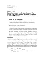
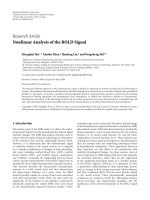
Figure 10 compares the (p, q)-optimal α
SAM,fading
versus η
and the p
t
-optimal α
ALOHA,fading
versus η for each of the three
topologies under
= 1 (omnidirectional antennas) and =
0.01 (directional antennas), respectively. We see that when η
is optimal ly chosen, the throughput of the SAM is about 2 to
3 times the throughput of the ALOHA.
6. CONCLUSIONS
In this paper, we have analyzed the throughput of large wire-
less networks with three regular topologies (square, hexag-
onal, and triangular). Two medium-access control schemes
have been considered: synchronous array method (SAM)
and a random-access method called slotted ALOHA. We
have found that the three topologies do not change the net-
work throughput significantly although the hexagonal topol-
ogy has the smallest delay and the triangular topology has
the largest delay. Our comparison between SAM and slotted
ALOHA for fading channels shows that the SAM has a signif-
icantly higher throughput than slotted ALOHA. This finding
is similar to a previous comparison between SAM and slotted
ALOHA for nonfading channels.
Future work should consider protocols such as carrier-
sense multiple access with collision avoidance (CSMA/CA).
This protocol has been analyzed for small-size networks [8].
It should be useful to evaluate its performance in the con-
text of large networks. Using fundamental throughput units
such as bits-hops/s/Hertz/node should all ow a f air compari-
son with SAM, ALOHA, as wel l as other schemes.
It is also useful to mention that directional antennas have
been addressed by MAC researchers in recent years, for ex-
ample, see [9]. But the work shown in this paper and [2]ap-
pears the first to provide a precise measure of the throughput
gain using directional antennas.
K. Hong and Y. Hua 11
−10 −50 5101520
0
0.05
0.1
0.15
0.2
= 1Triangle
SAM
Slotted ALOHA
−10 −50 5101520
0
0.05
0.1
0.15
0.2
= 1Hexagon
−10 −50 5101520
0
0.05
0.1
0.15
0.2
= 1Square
−10 −50 5 101520
0
0.5
1
1.5
Triangle
= 0.01
SAM
Slotted ALOHA
−10 −50 5101520
0
0.5
1
0.2
Hexagon
= 0.01
−10 −50 5101520
0
0.5
1
1.5
= 0.01
Square
Figure 10: The (p, q)-optimal α
SAM,fading
versus η in dB and the p
t
-optimal α
ALOHA,fading
versus η in dB for three topologies, n = 4, and
SNR
0
= 30 dB. The left column of plots is for = 1 (omnidirectional antennas). The right column of plots is for = 0.01 (directional
antennas).
ACKNOWLEDGMENTS
This work was supported in part by the US National Science
Foundation under Grant no. TF-0514736, and the US Army
Research Office under the MURI Grant no. W911NF-04-1-
0224. Part of this work was presented at IEEE Workshop on
Sensor Arr ay and Multichannel Processing, Waltham, Mass,
July 2006.
REFERENCES
[1] X. Liu and M. Haenggi, “Throughput analysis of fading sen-
sor networks with regular and random topologies,” EURASIP
Journal on Wireless Communications and Networking, vol. 2005,
no. 4, pp. 554–564, 2005.
[2] Y. Hua, Y. Huang, and J. J. Garcia-Luna-Aceves, “Maximizing
the throughput of large ad hoc wireless networks,” IEEE Signal
Processing Magazine, vol. 23, no. 5, pp. 84–94, 2006.
[3] L L. Xie and P. R. Kumar, “A network information theory for
wireless communication: scaling laws and optimal operation,”
IEEE Transactions on Information Theory,vol.50,no.5,pp.
748–767, 2004.
[4] F. Xue, L L. Xie, and P. R. Kumar, “The transport capacity of
wireless networks over fading channels,” IEEE Transactions on
Information Theory, vol. 51, no. 3, pp. 834–847, 2005.
[5] S. Yi, Y. Pei, and S. Kalyanaraman, “On the capacity improve-
ment of ad hoc wireless networks using directional antennas,”
in Proceedings of the the 4th ACM International Symposium on
Mobile Ad Hoc Networking and Computing (MobiHoc ’03),pp.
108–116, Annapolis, Md, USA, June 2003.
[6] IEEE Transactions on Information Theory, vol. 31, no. 2, 1985,
special issue on Random-Access Communications.
[7] B. Zhao and Y. Hua, “A distributed medium access control
scheme for a large network of wireless routers,” submitted to
IEEE Transactions on Wireless Communications.
[8] G. Bianchi, “Performance analysis of the IEEE 802.11 dis-
tributed coordination function,” IEEE Journal on Selected Areas
in Communications, vol. 18, no. 3, pp. 535–547, 2000.
[9]T.Korakis,G.Jakllari,andL.Tassiulas,“AMACprotocol
for full exploitation of directional antennas in ad-hoc wire-
less networks,” in Proceedings of the the 4th ACM Interna-
tional Symposium on Mobile Ad Hoc Networking and Computing
(MobiHoc ’03), pp. 98–107, Annapolis, Md, USA, June 2003.