Báo cáo hóa học: " Research Article Turbo Decision Aided Receivers for Clipping Noise Mitigation in Coded OFDM" pdf
Bạn đang xem bản rút gọn của tài liệu. Xem và tải ngay bản đầy đủ của tài liệu tại đây (803.98 KB, 10 trang )
Hindawi Publishing Corporation
EURASIP Journal on Wireless Communications and Networking
Volume 2008, Article ID 352597, 10 pages
doi:10.1155/2008/352597
Research Article
Turbo Decision Aided Receivers for Clipping Noise
Mitigation in Coded OFDM
Maxime Colas,
1
Guillaume Gelle,
1
and David Declercq
2
1
D
´
ecom-Crestic Lab, University of Reims Champagne-Ardenne, BP 1039, 51687 Reims Cedex 2, France
2
ETIS Lab, Ecole Nationale Sup
´
erieure de l’Electronique et de ses Applications, 6 Avenue du Ponceau,
95014 Cergy Pontoise Cedex, France
Correspondence should be addressed to Guillaume Gelle,
Received 11 July 2006; Revised 26 January 2007; Accepted 31 August 2007
Recommended by Luc Vandendorpe
Orthogonal frequency division multiplexing (OFDM) is the modulation technique used in most of the high-rate communication
standards. However, OFDM signals exhibit high peak average to power ratio (PAPR) that makes them particularly sensitive to
nonlinear distortions caused by high-power amplifiers. Hence, the amplifier needs to operate at large output backoff,thereby
decreasing the average efficiency of the transmitter. One way to reduce PAPR consists in clipping the amplitude of the OFDM
signal introducing an additional noise that degrades the overall system performance. In that case, the receiver needs to set up an
algorithm that compensates this clipping noise. In this paper, we propose three new iterative receivers with growing complexity
and performance that operate at severe clipping: the first and simplest receiver uses a Viterbi algorithm as channel decoder whereas
the other two implement a soft-input soft-output (SISO) decoder. Each soft receiver is analyzed through EXIT charts for different
mappings. Finally, the performances of the receivers are simulated on both short time-varying channel and AWGN channel.
Copyright © 2008 Maxime Colas et al. This is an open access article distributed under the Creative Commons Attribution License,
which permits unrestricted use, distribution, and reproduction in any medium, provided the original work is properly cited.
1. INTRODUCTION
Orthogonal frequency division multiplexing (OFDM) is a
modulation technique used in many new and emerging
broadband technologies either wired for the ADSL (asym-
metric digital subscriber line) or wireless single or multi-
users as in DAB (digital audio broadcasting), DVB-T (digital
video broadcasting-terrestrial), wireless LANs, and so forth
[1]. In all these systems, the information data stream is trans-
mitted in parallel on several orthogonal subcarriers, each
subcarrier being QAM or PSK modulated. The main advan-
tage of OFDM is both its bandwidth efficiency and its abil-
ity to counter multipath fading without requiring complex
equalizer [2]. Moreover, OFDM can be easily implemented
using FFT. However, a well-known drawback of OFDM is
that transmitted signals exhibit a Gaussian time-domain
waveform with large amplitude range and high peak to av-
erage power ratio (PAPR) which make OFDM particularly
sensitive to nonlinear distortions caused by the high power
amplifier (HPA). Classically, the mitigation of these nonlin-
ear distortions is partially performed by a pre-distorter which
inverts the HPA characteristic [3, 4]. Additionally, the HPA
operates at a large power input backoff (IBO) to ensure a dis-
tortionless transmission. So, the obvious disadvantage of fix-
ing a large IBO is that the maximum transmission power is
much higher than necessary.
Two kinds of approaches can be distinguished to deal
with high PAPR signals. The first approach is to generate
OFDM signals with a low PAPR without information loss.
Many of these PAPR reduction techniques have been pro-
posed in the literature, using selective mapping [5, 6]or
phase shifting [7]. The second way to reduce the PAPR is
deliberately to clip the peaks with high amplitude [8]. The
power ratio in dB between the squared clipping amplitude
A
2
and the OFDM signal power σ
2
x
is called clipping ratio
(CR). Clearly, the clipping operation causes some degrada-
tion due to the nonlinear operation which requires specific
compensation. Two classes of clipping techniques have been
described in the literature as follows.
(1) The first one clips the OFDM signal after oversam-
pling of the output of the IFFT. The clipping oper-
ation causes both in-band and out-of-band (OOB)
2 EURASIP Journal on Wireless Communications and Networking
distorsion of the OFDM signal. The OOB distorsion
can be mitigated by bandpass filtering which in turn
causes some peak regrowth [9].
(2) The second approach proposes to clip the OFDM sam-
ples without interpolation. In that case, the bandpass
filtering for OOB radiation removal is useless because
all the clipping noise falls in band. Hence, this oper-
ation must be associated with efficient in-band noise
mitigation receivers [10, 11].
In this paper, we focus on the latter clipping technique,
which requires clipping noise mitigation at the Nyquist sam-
pling rate only. Assuming that the HPA-IBO is fixed at a suf-
ficiently high level, the power amplifier operates in its lin-
ear region and thus only the problem of in-band noise miti-
gation is considered. However, the algorithms presented can
readily be extended for oversampled OFDM frames.
When using deliberate clipping, the receiver needs to re-
build the clipped peaks before the symbol detection in order
to compensate the information loss. An attractive method
has been proposed in [10, 11], which consists in the itera-
tive reconstruction of the peak amplitudes by successive hard
decisions both in time and frequency domain. This method
is called decision-aided reconstruction (DAR). When using
coded OFDM modulation as in wireless communication sys-
tems on severe fading mutipath channels, it can be inter-
esting to jointly use the channel decoder and the clipping
noise mitigation process (DAR). The purpose of this paper
is to provide some insights on the joint decoding/clipping
noise mitigation through the introduction of a class of algo-
rithms named Turbo-DAR (turbo decision-aided reconstruc-
tion) which are able to operate at severe clipping ratios. The
guiding principle of a Turbo-DAR receiver is to perform sev-
eral iterations of a receiver composed of a clipping noise mit-
igation block and a channel decoder, in a turbo fashion.
We present three Turbo-DAR receivers for convolution-
ally coded transmission, with growing complexity and per-
formance. The simplest receiver uses a Viterbi decoder, and is
therefore called Hard-Turbo-DAR. The second receiver uses
a soft-input soft-output (SISO) decoder (BCJR algorithm) in
place of the Viterbi decoder and is called Soft-Turbo-DAR.
Finally, we take advantage of the bit interleaved coded mod-
ulation (BICM) structure of the receiver and propagates the
soft extrinsic information backward to the symbol demap-
per. This receiver is called Turbo-DAR-BICM.
An approach similar to the Soft-Turbo-DAR has already
been proposed in [12], however, our system mitigates the
clipping noise whereas their receiver iteratively estimates and
substracts the Bussgang noise from oversampled OFDM sig-
nals, which is less general.
Thanks to the propagation of soft extrinsic values, the
Soft-Turbo-DAR and the Turbo-DAR-BICM can be theoret-
ically studied with the help of well-known EXIT charts [13].
We have therewith compared the different receiver behaviors
with respect to the symbol mapping of the QAM constella-
tion, and we especially show that the mapping has to be cho-
sencarefullyforeachreceivertype.
The paper is organized as follows. In Section 2,wemake
a brief presentation of the communication system and
UC X
x
c
x
G
π
Convolutional
code
QAM
mapping
Soft
limiter
// to serial
Cyclic prefix
IFFT
Serial to //
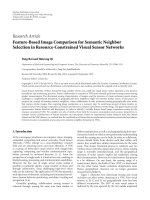
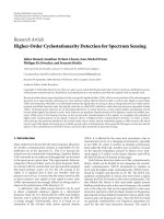
OFDM emitter
Figure 1: OFDM transmission system with soft limiter that simu-
latesthepoweramplifiereffect.
the introduction of useful notations. Then, the three re-
ceivers (Hard-Turbo-DAR, Soft-Turbo-DAR and Turbo-
DAR-BICM)arepresentedindetailinSection 3.Aconver-
gence analysis with EXIT charts is presented in Section 4 for
the two latter receivers, and a discussion about the suited
mapping choice is given. Finally, in Section 5, we discuss the
validity of our approach and the advantages of our receivers
based on simulations over AWGN and slow time-varying fre-
quency selective (STVFS) channels. We show in particular
that the Turbo-DAR receivers can compensate for almost all
the clipping noise for CR as small as 1 dB. This result is re-
ally interesting since it shows that one can possibly accept a
much lower CR than those usually used in practice, thereby
improving the power efficiency of the OFDM transmission.
2. TRANSMITTER AND CHANNEL MODEL
In the sequel, capital letters stand for frequency domain sig-
nals and bold notations represent frame vectors. The
·
†
op-
erator denotes an interleaved vector or the interleaved val-
uesofavector.AsdescribedonFigure 1,alengthK
b
binary
sequence U is encoded via a convolutional code to obtain a
length N
b
coded binary sequence C. Then, the sequence C is
interleaved with a pseudorandom interleaver
{π(n)}
n=0 N
b
−1
,
and we denote by C
†
the output of the interleaver. C
†
is
mapped on N
b
/log
2
(M) = N symbols X belonging to a M-
QAM constellation. The output of the OFDM modulator
is obtained with an N-point inverse fast Fourier transform
(IFFT) as
x
n
=
1
√
N
N−1
k=0
X
k
exp
2jπnk
N
,0
≤ n ≤ N −1, (1)
where X
={X
k
}
N−1
k
=0
are the coded QAM symbols and N is
the OFDM block size.
In order to cancel both the inter carrier and inter-block
interference, a cyclic prefix is added to the OFDM block as
x
G
n
= x
(n+N−G)
N
,0≤ n ≤ N + G − 1, (2)
where G the length of the cyclic prefix is assumed to be
longer than the channel memory, and (k)
N
is the residue of
Maxime Colas et al. 3
k modulo N. Finally, the clipping operation is implemented
with a soft limiter applied on the time-sequence x
G
as fol-
lows:
x
c
n
=
⎧
⎨
⎩
x
G
n
x
G
n
≤
A,0≤ n ≤ N + G −1,
A exp
arg x
G
n
x
G
n
>A,0≤ n ≤ N + G −1,
(3)
where x
c
={x
c
n
}
N+G−1
n
=0
is the clipped output sequence and
A is the clipping amplitude. This clipping operation applies
only on the amplitude of the OFDM values, and the phase of
the OFDM values remain unchanged.
The clipping ratio (CR) is defined as
CR
= 10 log
10
A
2
σ
2
x
dB, (4)
where σ
2
x
is the mean power of the OFDM symbols before
clipping.
The samples x
c
are then transmitted through a channel
defined by its spectrum
{H
k
}
k=0 N−1
.Inthispaper,twotypes
of channels are considered: the AWGN channel with M-QAM
inputs for which the spectrum is flat H
k
= C
te
,andafre-
quency selective channel which could vary from one OFDM
block to another, that we call slow time-varying frequency se-
lective (STVFS) channel. Although the channel could vary,
we assume that an accurate estimator of the channel spec-
trum is available at the receiver. We also assume a perfect
carrier and timing synchronization of the receiver. Moreover,
considering the clipped signal sampled at the Nyquist rate
and a linear power amplification, the impact of the OOB ra-
diation will not be addressed in the paper. So only the in-
band noise is mitigated by our algorithms.
Throughout this paper, we define E
b
/N
0
as the mean
transmitted energy per information bit to channel noise
power ratio
E
b
N
0
=
E
s
E
ch
(N + G)
2R·σ
2
b
·log
2
(M)N
,(5)
where R is the coding rate of the convolutional code, σ
2
b
is
the variance on the real and imaginary parts of the channel
noise, E
ch
=
k
|H
k
|
2
represents the channel gain, and G/N
is the additional energy ratio required for the transmission of
the cyclic prefix. The mean power per symbol sent through
thechannelisdenotedE
s
. Assuming that the OFDM signal is
composed of i.i.d. samples distributed as complex Gaussian,
E
s
depends on the clipping level A and on the constellation
power P
c
such as E
s
= P
c
(1−exp(−A
2
/P
c
)). In the sequel, we
use rectangular M-QAM constellation with symbols on odd
integer coordinates, so P
c
= 2(M − 1)/3.
In the next section, we describe a class of iterative re-
ceivers with growing complexity, whose goal is to solve ef-
ficiently the estimation and reconstruction of the clipping
noise.
3. CLASS OF TURBO-DAR RECEIVERS
3.1. General principle
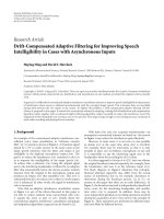
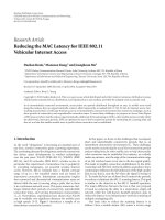
According to Figure 2, the signal at the receiver input after
cyclic prefix removal is transformed by a direct N-points FFT
and equalized to compensate for the channel selectivity (only
for the STVFS channel). The equalizer used in our study is
the MMSE equalizer in the frequency domain, performed by
multiplying each subcarrier of the OFDM block by
K
k
=
H
∗
k
H
k
2
+ N
0
/E
s
, k = 0 ···N −1. (6)
The choice of the MMSE equalizer is motivated by the fact
that it reduces the amplitude of the errors and prevents er-
ror propagation during the iterative process. We have com-
pared the receiver performance with other types of equalizers
to verify this statement.
The principle basis of Turbo-DAR receivers is to iterate
between the symbol decoder, whichiscomposedofanFEC
decoder and a symbol mapper, and the decision-aided recon-
struction (DAR) of the clipping noise only. In Figure 2, the
symbol decoder corresponds to the Hard-Turbo-DAR that
is presented in detail in the next section. Using this type of
receiver, the FEC code aims at correcting the additive white
Gaussian noise and a small part of the clipping noise, while
the DAR loop is used to help the FEC decoder by correcting
part of the clipping noise. All receivers described in this pa-
per focus on improving the cooperation between these two
blocks (symbol decoder and DAR loop).
The clipping amplitude defined in (3)isassumedtobe
known at the receiver side and is used in the DAR loop for
the detection of peaky samples. One iteration of a Turbo-
DAR receiver is described thereafter, and only the structure
of the symbol detector changes from one Turbo-DAR receiver
to another.
(1) The equalized signal Z serves as initialization at the
first iteration
X
(0)
= Z.
(2) In the ith
≥ 1 iteration, the noisy symbols
X
(i)
feed
the symbol decoder. The symbol decoder aims at denoising
the QAM symbols with the help of the channel decoder. The
three steps of the symbol decoder are then (i) a QAM demap-
per that is performed with the maximum a posteriori (MAP)
criterion, (ii) a channel decoder that is either hard output or
soft output, depending on the Turbo-DAR receiver type, and
(iii) a symbol mapper that transforms the output of the chan-
nel decoder into symbols of the QAM constellation (hard
output case), or soft symbols (soft output case). The output
of the symbol decoder is denoted
X
(i)
.
(3) The values
X
(i)
are propagated backwards to the input
of the symbol decoder through the DAR loop. In the DAR
loop,
X
(i)
is converted in time domain to reconstruct an es-
timated version of the OFDM block
x
(i)
. Then, a detector is
used to locate and replace the samples that are assumed to be
clipped at the transmitter:
∀n = 0 ···N −1, x
(i+1)
n
=
⎧
⎨
⎩
x
(0)
n
if
x
(i)
n
≤
A,
x
(i)
n
if
x
(i)
n
>A.
(7)
Hence, the time-domain output of the DAR loop is consti-
tuted of samples issued from the symbol decoder (those lo-
cated at indices where clipping has been detected by the DAR
loop) and of unaltered samples received from the channel
4 EURASIP Journal on Wireless Communications and Networking
Z
C
(i)
X
(0)
π
−1
π
Channel QAM mapping
// to serial
FFT
Serial to //
OFDM receiver
Equalizer
FFT
Prefix removal
Serial to //
// to serial
Iteration (0)
Iteration (i +1)
i
≥ 0
QAM demapping
(MAP)
X
(i+1)
X
(i)
Ve t e r bi
decoder
Symbol decoder
|x
(i)
| >A
// to serial
IFFT
Serial to //
// to serial
IFFT
Figure 2: Principle of Turbo-DAR class of receivers.
(where no clipping is detected). These mixed samples are
then used in the frequency domain as new noisy symbols
for the input of the symbol decoder. Note that our system
is strictly equivalent to a clipping noise n
ck
estimation, fol-
lowed by a subtraction step as follows:
n
(i)
c
n
=
⎧
⎨
⎩
0if
x
(i)
n
≤
A,
x
(i)
n
− x
(0)
n
if
x
(i)
n
>A,
x
(i+1)
n
= x
(0)
n
− n
(i)
c
n
.
(8)
We have chosen, in this work, to keep the DAR loop as
reconstruction tool for the clipped samples, and our main
concern is to try to increase the symbol protection in or-
der to help the DAR loop at each iteration. Note that the
DAR loop is not optimal because it does not take the clip-
ping noise probability density function into account, and
that other more efficient clipping noise mitigation methods
can be proposed, based, for examble, on optimal Bayesian
estimators [14], but at the expense of a large complexity in-
crease. A receiver using the DAR reconstruction is a good
tradeoff between implementation cost and performance.
As stated in [15], a 4-time oversampling is generally ad-
vised at the emitter before the clipping step for a efficient
peak regrowth limitation. In that case, the DAR loop can eas-
ily be modified by using zero-padded IFFT as its input well
as filtering and undersampling at its output.
The next subsection presents the structure of the simplest
Turbo-DAR receiver. Then, two soft extensions of this algo-
rithm are described and analysed in the next subsections.
3.2. The Hard-Turbo-DAR receiver
In this part, we briefly present the structure of the Hard-
Turbo-DAR receiver. As in the original DAR method [10],
the Hard-Turbo-DAR focusses on the design of a low-
complexity receiver. As we assume convolutional coding in
the OFDM system, the Viterbi algorithm is used as FEC de-
coder. Although using a hard decision decoder can appear
to be inappropriate in a turbo loop, it has the advantage of
a reduced receiver complexity compared to a soft-input soft-
output (SISO) channel decoder. Such a receiver is clearly sub-
optimal, but the Hard-Turbo-DAR aims at correcting jointly
the AWGN noise and the clipping noise with the minimum
complexity.
The symbol decoder of the Hard-Turbo-DAR follows the
three steps (see Figure 2) as follows.
(sd
1
) from noisy symbols
X
(i)
, we build an interleaved
a posteriori probabilities vector (denoted app
†(i)
1
=
{
app
1
(C
†
k,l
)
(i)
}
k=0···N−1, l=0···log
2
(M)−1
) at the bit level
using a MAP QAM demapper:
app
1
C
†
k,l
(i)
= P
C
†
k,l
|
X
(i)
k
=
s∈S
P
C
†
k,l
| s
P
s |
X
(i)
k
∝
s∈S
P
X
(i)
k
| s
∝
s∈S
exp −
X
(i)
k
− K
k
H
k
s
2
K
k
2
N
0
,
(9)
where C
†
k,l
is the lth bit (l = 0···log
2
M − 1) of the
kth M-QAM symbol (k
= 0···N −1). The M-QAM
constellation set is denoted S and S
is the subset of
symbols with a binary mapping which has the lth bit
equal to C
†
k,l
.
These APP are deinterleaved and used at the input of
the Viterbi decoder. The input of the Viterbi decoder
is then the APP vector app
(i)
1
={app
1
(C
n
)
(i)
}
n=0 N
b
−1
with the indices values n = π
−1
(k log
2
M + l).
Maxime Colas et al. 5
π
−1
π
QAM demapping
(MAP)
Soft QAM
mapping
BCJR
decoder
app
(i)
1
app
(i)
2
ext
(i)
2
X
(i)
X
(i)
C
(i)
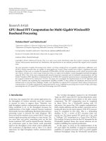
Figure 3: Structure of the Soft-Turbo-DAR symbol decoder.
(sd
2
) the Viterbi decoder computes the maximum likeli-
hood decoded sequence
C
(i)
. The decoded codeword
is used to provide an estimation of the transmitted bits
U
(i)
at the ith iteration, and also used to get estimated
M-QAM symbols.
(sd
3
)
C
(i)
is interleaved, and hard mapped into symbols
X
(i)
with
X
(i)
k
∈ S. These estimated symbols are converted
back to time domain using IFFT leading to
x
(i)
.
From the reconstruction and demapping (7)and(9), it
can be noticed that the channel state information (CSI) is
only valid at the first iteration; in the next iterations, the
OFDM symbols
X
(i)
, i>0 depend on the equalized OFDM
symbols Z but also on the noiseless estimated OFDM frame
x
(i)
, i>0. As a result, the noise power |K
k
|
2
N
0
is generally
misestimated for these iterations. Based on this remark, fur-
ther improvement of the receiver could be possible. An ex-
ample of CSI estimation algorithm followed by a scaling of
the bits likelihoods at the input of the Viterbi decoder de-
pending of the SNR in each subcarrier can be found in [16].
As pointed out in [12, 17], this algorithm behaves like a
turbo receiver, despite the propagation of hard decided val-
ues. The “turbo effect” actually comes from the fact that the
clipping noise is spread on all coded symbols in the frequency
domain. So, the decoder which operates in the frequency do-
main takes benefits from this diversity. We will use this re-
ceiver for comparison with the improved receivers proposed
in the next sections.
3.3. The Soft-Turbo-DAR receiver
The Hard-Turbo-DAR receiver clearly does not take full ad-
vantage from the turbo principle since the Viterbi decoder
produces hard output values. In order to reach better perfor-
mance, we propose in this section a more complex receiver
based on an SISO channel decoder [18, 19]. In this paper,
we only consider the BCJR decoder. The ouput of the de-
coder is composed of log-density-ratios which are reliabil-
ity measures of the coded bits. In order to take advantage of
these soft values, we propose to use a soft symbol mapper to
produce soft symbols at the output of the symbol decoder.
The soft symbols at the ith iteration are still denoted
X
(i)
,
and can be interpreted as noisy M-QAM symbols. Because
all values computed in the symbol decoder are soft, we called
this receiver Soft-Turbo-DAR. As mentioned in the preced-
ing section, the DAR loop is unchanged in all Turbo-DAR
receivers, and only the symbol decoder is different. The three
steps of the Soft-Turbo-DAR symbol decoder are as follows
(cf. Figure 3).
(sd
1
) This step is unchanged. The QAM demapper is still
performed using the MAP criterion.
(sd
2
) The deinterleaved APPs of the coded bits app
(i)
1
(cf.
(9)) are used at the input of the BCJR decoder to
compute the extrinsic probabilities of the coded bits
ext
(i)
2
={ext
2
(C
n
)
(i)
}
n=0 N
b
−1
. These extrinsic values
are obtained from the BCJR equations (cf. [18]for
more details) using the following relation:
∀n ∈ 0 ···N
b
− 1, ext
2
(C
n
)
(i)
∝
app
2
(C
n
)
(i)
app
1
(C
n
)
(i)
,
(10)
where app
2
and ext
2
denotes respectively the apos-
teriori and the extrinsic output probabilities returned
by the SISO decoder. The a posteriori probabilities are
used to take a decision on the codeword
C
(i)
,orequiv-
alently, the information bits
U
(i)
at the last iteration.
(sd
3
) The extrinsic probabilities are interleaved and propa-
gated to the QAM mapper. At this stage, it is useful
to take advantage of the soft values on the coded bits
to build a soft QAM symbol based on the conditional
mean estimator
X
(i)
k
=
C
†
k,l
∈{0,1}, l=0···log
2
M−1
s
log
2
M−1
l=0
ext
2
C
†
k,l
(i)
,
(11)
where s denotes the symbol labelled by the bits
{C
†
k,l
}
l=0···log
2
M−1
. The choice of the conditional mean
estimator is discussed in conjonction with the binary
mapping choice in Section 4. The output of the soft
mapper is then a continuous value (in
C) that can be
interpreted as a noisy M-QAM symbol, with the resid-
ual noise (additive noise plus clipping noise) present at
the output of the FEC decoder at the ith iteration. The
soft symbols
X
(i)
are converted back to time domain
using IFFT leading to
x
(i)
that is used in the DAR loop.
Note also that the soft symbols are obtained with the
extrinsic probabilities, as in all turbo receivers.
3.4. An iterative BICM receiver using Turbo-DAR
principle: Turbo-DAR-BICM
One further step can be reached in the direction of improving
the symbol decoder by taking advantage of the inherent bit
6 EURASIP Journal on Wireless Communications and Networking
π
−1
π
π
QAM demapping
(MAP)
Soft QAM
mapping
BCJR
decoder
app
(i)
1
app
(i)
2
ext
(i)
2
X
(i)
X
(i)
C
(i)
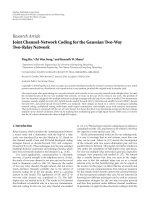
Figure 4: Structure of the Turbo-DAR-BICM symbol decoder.
interleaved coded modulation (BICM) structure of our trans-
mission system (Figure 1). We propose in this section to feed
back the extrinsic information at the SISO-FEC decoder to
the input of the QAM demapper, as is done in iterative BICM
receivers [20]. Consequently, the modified system now in-
cludes two loops. The overall complexity remains unchanged
although the EXIT charts analysis (cf. Section 4) will show
that this extra loop increases the number of iterations needed
to achieve convergence.
We have seen that the Soft-Turbo-DAR receiver mitigates
the clipping noise iteratively. However, it takes little advan-
tage of all available soft information provided by the decoder
for additive noise cancellation. As a matter of fact, it is possi-
ble to feed back the extrinsic probabilities ext
(i)
1
to the input
of the QAM demapper and use them as prior information
for the next iteration. The structure of the symbol decoder is
now depicted on Figure 4 and described thereafter.
(sd
2
) This step is unchanged, the deinterleaved probabilities
of the coded bits app
(i)
2
arestillusedtocomputethe
extrinsic LDR ext
(i)
1
and the a posteriori probabilities
app
(i)
1
with the BCJR algorithm. Hence, the extrinsic
probabilities are now used both to feed the soft map-
per and the input of the QAM demapper at the next
iteration.
(sd
3
) The QAM soft mapper is also unchanged and the con-
ditional mean estimator is still used. However, the
question of the map-labelling choice is reopened since
the binary labelling of the QAM constellation will now
serve in the soft symbol mapper, but also in the BICM
loop. The discussion of the map labelling will be illu-
minated in the next section with an EXIT chart study.
4. EXIT CHARTS ANALYSIS OF TURBO-DAR RECEIVERS
4.1. Analysis of the Soft-Turbo-DAR receiver
Although it increases significantly the overall complexity of
the symbol decoder, the use of a soft-output BCJR decoder
and a soft-symbol mapper allows the propagation of soft in-
formation during the decoding iterations leading to the so-
called turbo principle. Additionaly to the performance im-
provement, this framework allows us to use the EXIT Charts
proposed in [13] to analyse the behavior of the Soft-Turbo-
DAR receiver. Indeed, the Soft-Turbo-DAR receiver can be
considered as the concatenation of two soft-Input soft-Output
modules. The first one (called DAR loop in the sequel) is
constituted by the blocks which contain the soft mapper and
demapper as well as the comparator with the clipping ampli-
tude, FFT and IFFT components and the second one is the
BCJR channel decoder.
At the ith iteration, the DAR-loop denoted B
1
has in-
put ext
(i)
2
and output app
(i+1)
1
. Also at the ith iteration, the
BCJR block denoted B
2
has input app
(i)
1
and extrinsic out-
put ext
(i)
2
. Using these soft values, the extrinsic information
content I
B
1,2
(in) and I
B
1,2
(out) expressed in bit-per-channel
use (b/cu) are computed through Monte Carlo simulations
under the Gaussian assumption according to the equations
in [13, 21]. We can notice that the output of block B
1
is not
extrinsic to this block since it is not possible to remove the
contribution of its input in a simple manner. This problem
is mainly due to the soft symbol mapper and the FFT com-
ponents. Despite this drawback, we show in this section that
the EXIT chart analysis can fairly well predict the asymptotic
behavior of Soft-Turbo-DAR receiver, and also that it helps
us to choose the best binary mapping.
Choosing a good estimator of soft symbols from bit prob-
abilities is not an easy problem, and is encountered in many
otherturboreceivers(turboequalization[22]orturbosyn-
chronization [23]). The main problem comes from the fact
that the mapping of the QAM constellation (the bit labels
of each symbol) is related to the properties of the soft sym-
bol estimator. It is often adviced to rely on the Gray map-
ping combined to a conditional mean estimator to obtain
good soft symbols [22, 23]. Using an EXIT charts analysis,
we study the influence of the mapping choice on the Soft-
Tur bo-DA R receiver.
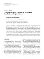
In Figure 5, we have drawn the EXIT chart at E
b
/N
0
=
8dBofblockB
2
corresponding to a convolutional code with
generators (5, 7)
|8
, and the EXIT chart of block B
1
with two
different types of binary mappings: the Gray mapping and
the modified set-partitioning mapping (MSP mapping) [24].
For both mappings, the MI at the output of block B
1
is constant when the input is lower than 0.5. This shows
that in this area, the system does not take advantage from
the iterative process. When the MI of B
1
input is greater
than 0.5, the output MI of the whole system progressively
increases and the Soft-Turbo-DAR enters in its iterative
Maxime Colas et al. 7
behavior. However, the convergence point lower than 1 pre-
vents Gray- and MSP-mapping based systems from converg-
ing at E
b
/N
0
= 8 dB to a very low bit error rate. The Gray
mapping is clearly more advantageous for a Soft-Turbo DAR
than the MSP mapping, so it appears that the Soft-Turbo-
DAR algorithm is unable to use the information provided by
high minimum squared Euclidean weight (MSEW) labelling
as in BICM-ID receivers [25]. We will reconsider this conclu-
sion in Section 4.
Finally, even for Gray labelling, the iterative process
reaches a fixed point (where the 2 curves intersect) lower
than 1 b/cu. So a residual error will remain asymptotical.
However, the numerical result presented in Section 5 show
that this residual error is low and that the Soft-Turbo-DAR
receiver allows a significant performance improvement com-
pared to the Hard-Turbo-DAR.
4.2. Discussion on the mapping choice for Turbo-DAR
BICM based on EXIT charts
Because of its different structure, the conclusion on the map-
ping choice made for the Soft-Turbo DAR cannot be gener-
alized to the Turbo-DAR BICM. In particular, we base our
study on the fact that the choice of the labelling is a crucial
issue in the design of BICM-ID receivers in order to achieve a
high coding gain over the iterations. In [24, 25], it was shown
that Gray labelling gives the best performance at the first de-
coding stage, but also achieves very low performance gain
with further decoding iterations of the algorithm. In fact, the
BICM-ID decoder takes advantage of a high MSEW of the
constellation when correct extrinsic information issued from
the decoder is used iteratively at the demapper input. Such
high MSEW labellings were introduced in [24, 25]: among
them, the modified set partitioning (MSP), which exhibits a
free Euclidean distance which is twice that of the Gray map-
ping, is presented as a good labelling map for QAM signaling
on both fading and AWGN channels.
The mapping choice cannot be directly generalized from
the BICM-ID to the Turbo-DAR BICM, due to the presence
of the soft mapping block in our receiver. The soft mapping
block builds soft symbols from the binary extrinsic probabil-
ities, using a conditional mean estimator. The MSP mapping
is not a good choice for the soft mapping block because sym-
bols with high reliability are spread everywhere in the con-
stellation, contrary to the Gray mapping case, where sym-
bols with high reliability are more concentrated. As a con-
sequence, the output of the soft mapper with MSP mapping
is biased and concentrated around the origin of the QAM
constellation. Therefore, the choice of the mapping has to be
balanced between the behavior of the soft mapper and that
of the BICM-ID decoder. A solution based on the use of the
MIX mapping introduced in [24],whichprovidesamixed
design between MSP and Gray mapping, is proposed in this
paper, and we show by EXIT charts analysis that it provides
a good tradeoff between the BICM-ID structure and an en-
hanced DAR-loop behavior.
Figure 6 draws the EXIT charts of the Turbo-DAR-BICM
receiver for differently labeled 16-QAM constellations. The
previous discussion is confirmed by the EXIT charts. The
0
0.1
0.2
0.3
0.4
0.5
0.6
0.7
0.8
0.9
1
BCJR
out
/DAR
in
(bit/cu)
00.10.20.30.40.50.60.70.80.91
BCJR
in
/DAR
out
(bit/cu)
BCJR decoder
Soft turbo-DAR Gray mapping
Soft turbo-DAR MSP mapping
Figure 5: EXIT charts of the Soft-Turbo-DAR receiver over AWGN
channel with CR
= 1dB, N = 64, E
b
/N
0
= 8 dB. The curve in solid
line with circles corresponds to the EXIT function of the DAR loop
with Gray mapping and that in solid line with diamonds represents
the EXIT function with MSP mapping.
0
0.1
0.2
0.3
0.4
0.5
0.6
0.7
0.8
0.9
1
BCJR
out
/DAR
in
(bit/cu)
00.10.20.30.40.50.60.70.80.91
BCJR
in
/DAR
out
(bit/cu)
BCJR decoder
TDBICM MIX mapping
TDBICM MSP mapping
Soft Turbo-DAR Gray mapping
Figure 6: EXIT charts of Soft-Turbo-DAR and Turbo-DAR-BICM
at E
b
/N
0
= 5.5dBandCR= 1 dB (AWGN channel).
tunnel is more open with the MIX mapping compared to
the MSP mapping. Note that the tunnel for the MSP map-
ping is open at the considered (E
b
/N
0
)
dB
.Thedrawbackof
the MIX mapping is that it seems that the Turbo-DAR BICM
converges to a fixed point which is not equal to 1 b/cu. This
means that we expect a residual error floor when using the
MIX mapping in the Turbo-DAR BICM. However, the fixed
point is very close to 1 b/cu, so the error floor can be very
low in practice, and this problem can be efficiently solved
8 EURASIP Journal on Wireless Communications and Networking
by using an extra outer error-correcting code with very high
rate. Also, it can be noticed that the Turbo-DAR BICM
performs better that the Soft Turbo-DAR with Gray mapping
after convergence. Although not presented, the EXIT chart of
Turbo-DAR BICM with Gray mapping is similar to the Soft-
Turbo DAR with Gray mapping: it was expected since a Gray
mapping does not bring any performance improvement in a
BICM-ID-based receiver.
As a conclusion, the use of MIX labelling provides a com-
promise between the DAR loop and the symbol decoder, and
we will verify this statement with finite length simulations in
the next section.
5. PERFORMANCE COMPARISON
5.1. Comparison between Hard-Turbo-DAR and
Soft-Turbo-DAR receivers
In this section, we present simulation results of the Soft-
Turbo DAR, and compare it to the Hard-Turbo DAR and
other types of receivers. The system parameters are N
= 64
16-QAM symbols per OFDM block with Gray mapping, and
a very severe clipping ratio of CR
= 1dB. In Figure 7,we
present the simulations over an AWGN channel, and Figure 8
presents the results over a STVFS channel. The considered
STVFS channel is composed of a 12-tap delay line dispersive
channel with independent random complex coefficients dis-
tributed as N (0,exp(
−βn)) where n = 0 ···11 and β is fixed
to 2.5 for our simulations. This value of β has been chosen to
exhibit frequency fades up to
−20 dB. Also, new channel re-
alizations are considered for each OFDM block in order to
model a block-stationarity behavior.
In each case, we compared four different receivers to a
lower bound (corresponding to a system without clipping
and a BCJR as channel decoder). The four receivers are as
follows.
(1) FEC-only: a receiver with no clipping noise mitigation,
which means that only the BCJR decoder tries to cor-
rect the Gaussian noise and the clipping noise,
(2) DAR + FEC: a receiver which uses a DAR clipping
noise mitigation before the BCJR decoder. Several iter-
ations of a DAR loop are used to mitigate the clipping
noise, then log-likelihood ratios are computed from
the corrected channel observations, and used as ini-
tialization for the BCJR decoder.
(3) Hard-Turbo DAR: the iterative receiver described in
Section 3.2. Only four iterations are used because the
convergence of this iterative receiver is very fast due to
the hard decisions taken in the loop.
(4) Soft-Turbo DAR: the improved receiver described in
Section 3.3. Only four iterations of this receiver were
also used since more iterations showed only minor im-
provements.
Figures 7 and 8 clearly illustrate the effectiveness of
the Turbo-DAR receivers when the clipping noise is strong.
For the AWGN channel, at such a low clipping ratio, the
DAR + FEC receiver provides very little BER improvement
whereas at BER
= 10
−4
, the Hard-Turbo-DAR receiver per-
10
−1
10
−2
10
−3
10
−4
10
−5
BER
2 4 6 8 10 12 14
E
b
/N
0
(dB)
FEC only
DAR (4 it.) + FEC
Hard Turbo-DAR (4 it.)
Soft Turbo-DAR (4 it.)
Lower bound
Figure 7: BER performance comparison of different receivers in the
presence of clipping noise over AWGN channel. Only the last itera-
tion of the receivers is shown. The parameters are CR
= 1dB, N =
64, and a 16-QAM with Gray mapping.
10
−1
10
−2
10
−3
10
−4
BER
3 4 5 6 7 8 9 1011121314
E
b
/N
0
(dB)
FEC only
DAR (4 it.) + FEC
Hard Turbo-DAR (4 it.)
Soft Turbo-DAR (4 it.)
Lower bound
Figure 8: BER performance comparison of different receivers in the
presence of clipping noise over STVFS channel. Only the last itera-
tion of the receivers is shown. The parameters are CR
= 1dB,N =
64, and a 16-QAM with Gray mapping.
forms more than 3 dB better than existing receivers, and an-
other 2 dB gain is obtained with the Soft-Turbo DAR. We can
see in Figure 8 that similar comments can be made for the
STVFS channel, which shows the robuteness of our approach
to the transmission channel spectrum.
Those results show that the complexity increase of the
Soft-Turbo-DAR receiver is justified by the performance gain
that is observed. Also, the Soft-Turbo DAR operates quite
Maxime Colas et al. 9
close to the lower bound (1 dB), which shows that this
receiver is close to optimal despite the use of suboptimal
components like the soft symbol mapper and the DAR loop.
As a conclusion, we stress the fact that the Turbo-DAR
receivers are very interesting solutions since they can com-
pensate for a great part of clipping noise even at very severe
clipping ratios. The CR is fixed here at 1 dB while it is usually
fixed around 4-5 dB in existing OFDM systems.
5.2. Performance improvement brought by the
Turbo-DAR-BICM receiver
The asymptotical results given by the EXIT charts for the
AWGN channel are confirmed by the BER performance pre-
sented in Figure 9. In this figure, we compare the Turbo-
DAR-BICM receiver with MIX and MSP mappings with the
results of the Soft-Turbo DAR, and with the corresponding
lower bounds, that is, a BICM-ID receiver without any clip-
ping noise.
As expected, the Turbo-DAR BICM with the MIX map-
ping performs better than with the MSP mapping in the con-
vergence region as a performance gain of more than 1 dB
is seen up to a BER
= 10
−4
.Theerrorfloorpredictedby
the EXIT charts analysis appears at BER
= 10
−5
. The perfor-
mance gain compared to the Soft-Turbo DAR is very impor-
tant, and shows the interest of feeding back the soft extrin-
sic values to the demapper, with a relatively small complexity
increase. Also, the Turbo-DAR-BICM curves are not too far
from the lower bounds, but there is still some gap to be filled
and this opens prospects for further research.
Again, we show that our receivers are robust to the fre-
quency selectivity of the channel by plotting results for a
STVFS channel in Figure 10, although, the gap to the lower
bounds is much larger in this case.
6. CONCLUSION
In this paper, we have proposed three receivers with growing
complexity and performance for clipping noise mitigation.
The Turbo-DAR receivers combine iteratively the clip-
ping level information and the FEC decoder in order to pro-
vide an overall correction that greatly outperforms the “DAR
+FEC”receiver.
The introduction of an FEC inside the DAR loop enables
the mitigation of the clipping noise with CR as low as 1dB.
Such a strong clipping level allows to consider IBO at the
transmitter such that no further saturation occurs even after
digitaltoanalogconversion. The introduction of a MAP de-
coder and a soft symbol mapper in the DAR loop enable the
exchange of soft information between the decoder and the
clipping noise reconstruction. This modification improves
the performance results of more than 2 dB at BER
= 10
−4
with respect to the Hard-Turbo DAR for both AWGN and
STVFS channels, but at the expense of an extra computa-
tional complexity. An EXIT chart analysis shows that the
Gray mapping is the best suited for the Soft-Turbo-DAR al-
gorithm: it means that this receiver can be applied to many
existing multicarrier standards (e.g., IEEE 802.11a or Hiper-
lan II) without any transmitter modification.
10
−1
10
−2
10
−3
10
−4
10
−5
10
−6
BER
2345678910
E
b
/N
0
(dB)
Lower-bound MSP mapping
Lower-bound MIX mapping
Soft Turbo-DAR (4 it.)
TD-BICM MSP mapping (8 it.)
TD-BICM MIX mapping (8 it.)
Figure 9: BER comparison of the Turbo-DAR-BICM (MIX and
MSP mappings) with the Soft-Turbo-DAR for AWGN channel with
16-QAM, CR
= 1dB,N = 64.
10
−1
10
−2
10
−3
10
−4
BER
345678910
E
b
/N
0
(dB)
Lower-bound MSP mapping
Lower-bound MIX mapping
Soft Turbo-DAR (4 it.)
TD-BICM MSP mapping (8 it.)
TD-BICM MIX mapping (8 it.)
Figure 10: BER comparison of the Turbo-DAR-BICM (MIX and
MSP mappings) with the Soft-Turbo-DAR for the STVFS channel,
the parameters of the receiver are the same as those in Figure 8.
As our iterative receiver partially relies on a BICM
scheme, the Soft-Turbo-DAR receiver can easily be modi-
fied to jointly behave as a DAR system and a BICM-ID de-
coder. With this modification, even the nonclipped samples
are processed at each iteration. The Turbo-DAR-BICM re-
ceiver strongly depends on the map labelling choice and the
10 EURASIP Journal on Wireless Communications and Networking
EXIT charts analysis shows that a mixed mapping provides
a good tradeoff between the labelling needed by the apos-
teriori soft symbol mapper and high MSEW needed by the
BICM-ID decoder.
The proposed receivers are still away from the lower
bounds, which seems to indicate that some improvement can
still be done. As a matter of fact, we did not question in our
work the DAR block, and one can wonder if the replacement
of the clipped samples only in the DAR loop is still efficient
when a capacity-approaching coding scheme is used. In that
case, performance improvement is expected by the investi-
gation of other (and probably more complex) clipping noise
estimators in the feedback loop. Future work will focus on
this last point.
REFERENCES
[1] A.R.S.BahaiandB.R.Saltzberg,Multi-Carrier Digital Com-
munications: Theory and Applications of OFDM,KluwerAca-
demic/Plenum Publishers, New York, NY, USA, 1999.
[2]L.Hanzo,M.M
¨
unster, B. J. Choi, and T. Keller, OFDM
and MC-CDMA for Broadband Multi-User Communications,
WLANs and Broadcasting, John Wiley & Sons, New York, NY,
USA, 2003.
[3] T. M. Nguyen, J. Yoh, C. H. Lee, H. T. Tran, and D. M. Johnson,
“Modeling of HPA and HPA linearization through a predis-
torter: global broadcasting service applications,” IEEE Trans-
actions on Broadcasting, vol. 49, no. 2, pp. 132–141, 2003.
[4] A. N. D’Andrea, V. Lottici, and R. Reggiannini, “Nonlinear
predistortion of OFDM signals over frequency-selective fad-
ing channels,” IEEE Transactions on Communications, vol. 49,
no. 5, pp. 837–843, 2001.
[5] R. W. B
¨
auml, R. F. H. Fischer, and J. B. Huber, “Reducing the
peak-to-average power ratio of multicarrier modulation by se-
lected mapping,” Electronics Letters, vol. 32, no. 22, pp. 2056–
2057, 1996.
[6] H.Breiling,S.H.M
¨
uller-Weinfurtner, and J. B. Huber, “SLM
peak-power reduction without explicit side information,”
IEEE Communications Letters, vol. 5, no. 6, pp. 239–241, 2001.
[7] L. J. Cimini Jr. and N. R. Sollenberger, “Peak-to-average power
ratio reduction of an OFDM signal using partial transmit se-
quences,” IEEE Communications Letters, vol. 4, no. 3, pp. 86–
88, 2000.
[8] H. Ochiai and H. Imai, “Performance analysis of deliberately
clipped OFDM signals,” IEEE Transactions on Communica-
tions, vol. 50, no. 1, pp. 89–101, 2002.
[9] X. Li and L. J. Cimini Jr., “Effects of clipping and filtering
on the performance of OFDM,” IEEE Communications Letters,
vol. 2, no. 5, pp. 131–133, 1998.
[10] D. Kim and G. L. St
¨
uber, “Clipping noise mitigation for
OFDM by decision-aided reconstruction,” IEEE Communica-
tions Letters, vol. 3, no. 1, pp. 4–6, 1999.
[11] J. Tellado, L. M. C. Hoo, and J. M. Cioffi,“Maximum-
likelihood detection of nonlinearly distorted multicarrier
symbols by iterative decoding,” IEEE Transactions on Commu-
nications, vol. 51, no. 2, pp. 218–228, 2003.
[12] H. Chen and A. M. Haimovich, “Iterative estimation and can-
cellation of clipping noise for OFDM signals,” IEEE Commu-
nications Letters, vol. 7, no. 7, pp. 305–307, 2003.
[13] S. ten Brink, “Convergence behavior of iteratively decoded
parallel concatenated codes,” IEEE Transactions on Communi-
cations, vol. 49, no. 10, pp. 1727–1737, 2001.
[14] D. Declercq and G. B. Giannakis, “Recovering clipped OFDM
symbols with Bayesian inference,” in Proceedings of the IEEE
International Conference on Acoustics, Speech, and Signal Pro-
cessing (ICASSP ’00), vol. 1, pp. 157–160, Istanbul, Turkey,
June 2000.
[15] J. Tellado, Peak to average power reduction for multicarrier mod-
ulation, Ph.D. thesis, Standford University, Stanford, Calif,
USA, 1999.
[16]Y.Wang,J.H.Ge,B.Ai,P.Liu,andS.Y.Yang,“Asoftde-
cision decoding scheme for wireless COFDM with application
to DVB-T,” IEEE Transactions on Consumer Electronics, vol. 50,
no. 1, pp. 84–88, 2004.
[17] G. Gelle, M. Colas, and D. Declercq, “Turbo decision aided
reconstruction of clipping noise in coded OFDM,” in Proceed-
ings of the 5th IEEE Workshop on Signal Processing Advances in
Wireless Communications (SPAWC ’04)
, pp. 591–595, Lisbon,
Portugal, July 2004.
[18] L. Bahl, J. Cocke, F. Jelinek, and J. Raviv, “Optimal decoding of
linear codes for minimizing symbol error rate,” IEEE Transac-
tions on Information Theory, vol. 20, no. 2, pp. 284–287, 1974.
[19] J. Hagenauer and P. Hoeher, “A viterbi algorithm with
soft-decision outputs and its applications,” in Proceed-
ings of the IEEE Global Telecommunications Conference
(GLOBECOM ’89), vol. 3, pp. 1680–1686, Dallas, Tex, USA,
November 1989.
[20] X. Li and J. A. Ritcey, “Bit-interleaved coded modulation with
iterative decoding,” IEEE Communications Letters, vol. 1, no. 6,
pp. 169–171, 1997.
[21] T. J. Richardson and R. L. Urbanke, “The capacity of low-
density parity-check codes under message-passing decoding,”
IEEE Transactions on Information Theory,vol.47,no.2,pp.
599–618, 2001.
[22] D. Leroux, C. Laot, and R. Le Bidan, “Low-complexity MMSE
turbo equalization: a possible solution for EDGE,” IEEE Trans-
actions on Wireless Communications, vol. 4, no. 3, pp. 965–974,
2005.
[23]C.Herzet,V.Ramon,L.Vandendorpe,andM.Moeneclaey,
“EM algorithm-based timing synchronization in turbo re-
ceivers,” in Proceedings of the IEEE International Conference on
Acoustics, Speech, and Signal Processing (ICASSP ’03), vol. 4,
pp. 612–615, Hong Kong, April 2003.
[24] A. Chindapol and J. A. Ritcey, “Design, analysis, and perfor-
mance evaluation for BICM-ID with square QAM constella-
tions in Rayleigh fading channels,” IEEE Journal on Selected
Areas in Communications, vol. 19, no. 5, pp. 944–957, 2001.
[25] F. Schreckenbach, N. G
¨
ortz, J. Hagenauer, and G. Bauch,
“Optimization of symbol mappings for bit-interleaved coded
modulation with iterative decoding,” IEEE Communications
Letters, vol. 7, no. 12, pp. 593–595, 2003.