Báo cáo hóa học: " Research Article Thermal-Aware Scheduling for Future Chip Multiprocessors" pptx
Bạn đang xem bản rút gọn của tài liệu. Xem và tải ngay bản đầy đủ của tài liệu tại đây (2.69 MB, 15 trang )
Hindawi Publishing Corporation
EURASIP Journal on Embedded Systems
Volume 2007, Article ID 48926, 15 pages
doi:10.1155/2007/48926
Research Article
Thermal-Aware Scheduling for Future Chip Multiprocessors
Kyriakos Stavrou and Pedro Trancoso
Department of Computer Science, University of Cyprus, 75 Kallipoleos Street, P.O. Box 20537, 1678 Nicosia, Cyprus
Received 10 July 2006; Revised 12 December 2006; Accepted 29 January 2007
Recommended by Antonio Nunez
The increased complexity and operating frequency in current single chip microprocessors is resulting in a decrease in the perfor-
mance improvements. Consequently, major manufacturers offer chip multiprocessor (CMP) architectures in order to keep up with
the expected performance gains. This architecture is successfully being introduced in many markets including that of the embedded
systems. Nevertheless, the integration of several cores onto the same chip may lead to increased heat dissipation and consequently
additional costs for cooling, higher power consumption, decrease of the reliability, and thermal-induced performance loss, among
others. In this paper, we analyze the evolution of the thermal issues for the future chip multiprocessor architectures and show that
as the number of on-chip cores increases, the thermal-induced problems will worsen. In addition, we present several scenarios that
result in excessive thermal stress to the CMP chip or significant performance loss. In order to minimize or even eliminate these
problems, we propose thermal-aware scheduler (TAS) algorithms. When assigning processes to cores, TAS takes their temperature
and cooling ability into account in order to avoid thermal stress and at the same time improve the performance. Experimental
results have shown that a TAS algorithm that considers also the temperatures of neighboring cores is able to significantly reduce
the temperature-induced performance loss while at the same time, decrease the chip’s temperature a cross many different operation
and configuration scenarios.
Copyright © 2007 K. Stavrou and P. Trancoso. This is an open access article distributed under the Creative Commons Attribution
License, which permits unrestricted use, distribution, and reproduction i n any medium, provided the original work is properly
cited.
1. INTRODUCTION
The doubling of microprocessor performance every 18
months has been the result of two factors: more transistors
per chip and superlinear scaling of the processor clock with
technology generation [1]. However, technology scaling to-
gether with frequency and complexity increase result in a
significant increase of the power density. This trend, which
is becoming a key-limiting factor to the per formance of cur-
rent state-of-the-art microprocessors [2–5], is likely to con-
tinue in future generations as well [4, 6]. The higher power
density leads to increased heat dissipation and consequently
higher operating temperature [7, 8].
To handle higher operating temperatures, chip manu-
factures have been using more efficient and more expen-
sive cooling solutions [6, 9]. While such solutions were
adequate in the past, these packages are now becoming
prohibitively expensive, as the relationship between cool-
ing capabilities and cooling costs is not linear [4, 6]. To
reduce packaging cost, current processors are usually de-
signed to sustain the thermal requirement of typical work-
loads and utilize dynamic thermal management (DTM)
techniques when temperature exceeds the design-set point
[4, 10]. When the operating temperature reaches a prede-
fined threshold, the DTM techniques reduce the proces-
sor’spowerconsumptioninordertoallowittocooldown
[4, 6, 7, 11–13]. An example of such a DTM mechanism
is to reduce the consumed power through duty-cycle-based
throttling. While it is very effec tive achieving its goal, each
DTM event comes with a sig nificant performance penalty
[4, 7].
Moreover, the reliability of electronic devices and there-
fore of microprocessors depends exponentially on the opera-
tion temperature [4, 5, 14–17]. Viswanath et al. [5] note that
even small differences in operating temperature, in the order
of 10
◦
C–15
◦
C, can result in a 2x difference in the lifespan of
the devices.
Finally, higher temperature leads to power and energy
inefficiencies mainly due to the exponential dependence of
leakage power on temperature [4, 6, 7, 13]. As in future gen-
erations, leakage current is expected to consume about 50%
of the total power [1, 3] this issue will become more seri-
ous. Additionally, the higher the operating temperature is,
the more aggressive the cooling solution must be (e.g., higher
2 EURASIP Journal on Embedded Systems
fan speeds) which will lead to further increase in power con-
sumption [11, 12].
The chip multiprocessors (CMP) architecture has been
proposed by Olukotun et al. [2] as a solution able to extend
the performance improvement rate without further com-
plexity increase. The b enefits resulting from this architecture
are proved by the large number of commercial products that
adopted it, such as IBM’s Power 5 [18], SUN’s Niagara [19],
Intel’s Pentium-D [20], and AMD’s Athlon 64 X2 [21].
Recently, CMPs have been successfully used for multi-
media applications as they prove able to offer significant
speedup for these types of workload [22–24]. At the same
time, embedded devices have an increasing demand for mul-
tiprocessor solutions. Goodacre [25] states that 3 G handsets
may use parallel processing at a number of distinct levels,
such as when making a video call in conjunction with other
background applications. Therefore, the CMP architecture
will be soon used in the embedded systems.
The trend for future CMPs is to increase the number of
on-chip cores [26]. This integration is likely to reduce the
per-core cooling ability and increase the negative effects of
temperature-induced problems [27]. Additionally, the char-
acteristics of the CMP, that is, multiple cores packed together,
enable execution scenarios that can cause excessive thermal
stress and significant performance penalties.
To address these problems, we propose thermal-aware
scheduling. S pecifically, when scheduling a process for exe-
cution, the operating system determines on which core the
process will run based on the thermal state of each core,
that is, its temperature and cooling efficiency. Thermal-aware
scheduling is a mechanism that aims to avoid situations
such as creation of large hotspots and thermal violations,
which may result in performance degradation. Additionally,
the proposed scheme offers opportunities for performance
improvements arising not only from the reduction of the
number of DTM events but also from enabling per-core fre-
quency increase, which benefits significantly single-threaded
applications [10, 28]. Thermal-aware scheduling can be im-
plemented purely at the operating system level by adding
the proper functionality into the scheduler of the OS ker-
nel.
The contributions of this paper are the identification of
the thermal issues that arise from the technological evolu-
tion of the CMP chips, as well as the proposal and evaluation
of a thermal-aware scheduling algorithm w ith two optimiza-
tions: thermal threshold and neighborhood awareness.Toeval-
uate the proposed techniques, we used the TSIC simulator
[29]. The experimental results for future CMP chip config-
urations showed that simple thermal-aware scheduling algo-
rithms may result in significant performance degradation as
the temperature of the cores often reach the maximum al-
lowed value, consequently triggering DTM events. The addi-
tion of a thermal threshold results in a significant reduction
of DTM events and consequently in better performance. By
making the algorithm aware of the neighboring core thermal
characteristics (neighborhood aware), the scheduler is able to
take better decisions and therefore provide a more stable per-
formance comparing to the other two algorithms.
The rest of this paper is organized as follows. Section 2
discusses the relevant related work, Section 3 presents the
most important temperature-induced problems and analyzes
the effect they are likely to have on future chip multiproces-
sors. Section 4 presents the proposed thermal-aware schedul-
ing algorithms.
Section 5 describes the experimental setup
and Section 6 the experimental results. Finally, Section 7
presents the conclusions to the work.
2. RELATED WORK
As temperature increase is directly related to the consumed
power, techniques that aim to decrease the power consump-
tion a chieve temperature reduction as w ell. Different tech-
niques, however, target power consumption at different lev-
els.
Circuit-level techniques mainly optimize the physical,
transistor, and layout design [30, 31]. A common technique
uses different transistor types for different units of the chip.
The architectural-level techniques take advantage of the ap-
plication characteristics to enable on-chip units to consume
less power. Examples of such techniques include hardware
reconfiguration and adaptation [32], clock gating and mod-
ification of the execution process, such as speculation con-
trol [33]. At the application level, power reduction is mainly
achieved during the compilation process using specially de-
veloped compilers. What these compilers try to do is to ap-
ply power-aware optimizations during the application’s opti-
mization phase such as strength reduction and partial redun-
dancy elimination.
Another solution proposed to deal with the thermal is-
sues is thermal-aware floorplanning [34]. The rationale be-
hind this technique is placing hot parts of the chip in loca-
tions having more efficient cooling while avoiding the place-
ment of such parts adjacent to each other.
To handle situations of excessive heat dissipation, spe-
cial dynamic thermal management (DTM) techniques have
been developed. Skadron et al. in [4] present and evaluate
the most important DTM techniques, dynamic voltage and
frequency scaling (DVFS), units toggling and execution mi-
gration. DVFS decreases the power consumed by the micro-
processor’s chip by decreasing its operating voltage and fre-
quency. As power consumption is known to have a cubic re-
lationship with the operating frequency [35], scaling it down
leads to decreased power consumption and consequently de-
creased heat dissipation. Although very effective in achieving
its goal, DVFS introduces significant performance penalty,
which is related to the lower performance due to the de-
creased frequency and the overhead of the reconfiguration
event.
Toggling execution units [4], such as fetch engine tog-
gling , targets power consumption decrease indirectly. Specif-
ically, such techniques try to decrease the number of in-
structions on-the-fly in order to limit the consumed power
and consequently allow the chip to cool. The performance
penalty comes from the underutilization of the available re-
sources.
K. Stavrou and P. Trancoso 3
Execution migration [13] is another technique targeting
thermal issues and maybe the only one from those men-
tioned above, that does it directly and not through reducing
power consumption. When a unit gets too hot, execution is
migrated to another unit that is able to perform the same op-
eration. For this migration to be possible, replicated and idle
units must exist.
Executing a workload in a thermal-aware manner has
been proposed by Mooref et al. [12] for large data-centers.
Specifically, the placement of applications is such that servers
executing intensive applications are in positions favored by
the cold-air flow from the air conditioners. Thermal-aware
scheduling follows the same principles but applies this tech-
nique to CMPs.
Donald and Martonosi [36] present a throughout analy-
sis of thermal management techniques for multicore archi-
tectures. They classify the techniques they use in terms of
core throttling policy, which is applied locally to a core or
to the processor as a whole, and process migration policies.
The authors concluded that there is significant room for im-
provement.
3. CMP THERMAL ISSUES
The increasing number of transistors that technolog y ad-
vancements provide, will allow future chip multiprocessors
to include a larger number of cores [26]. At the same time, as
technology feature size shrinks, the chip’s area will decrease.
This section examines the effect these evolution trends will
have on the temperature of the CMP chip. We start by pre-
senting the heat transfer model that applies to CMPs and
then discuss the two evolution scenarios: smaller chips and
more cores on the same chip.
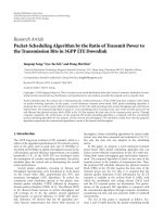
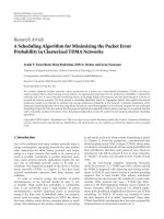
3.1. Heat transfer model in CMPs
Cooling in electronic chips is achieved through heat trans-
fer to the package and consequently to the ambient, mainly
through the vertical path (Figure 1(a)). At the same time,
there is heat transfer between the several units of the chip
and from the units to the ambient through the lateral path.
In chip multiprocessors, there is heat exchange not only be-
tween the units within a core but also across the cores that co-
exist on the chip (Figure 1(b)). As such, the heat produced
by each core affects not only its own temperature but also the
temperature of all other cores.
The single chip microprocessor of Figure 1(a),canemit
heat to the ambient from all its 6 cross-sectional areas
whereas each core of the 4-core CMP (Figure 1(b))canemit
heat from only 4. The other two cross-sectional areas neigh-
bor to other cores and cooling through that direction is feasi-
ble only if the neighboring core is cooler. Even if the temper-
ature of the neighboring core is equal to that of the ambient,
such heat exchange will be poor when compared to direct
heat dissipation to the ambient due to the low thermal resis-
tivity of silicon [4]. Furthermore, as the number of on-chip
cores increases, t here will be co res with o nly 2 “f ree” edges
(cross-sectional areas at the edge of the chip), further reduc-
ing the per-core cooling ability (Figure 1(c)). Finally, if the
chip’s area does not change proportional ly, the per-core “free”
cross-sectional area will reduce harming again the cooling
efficiency. All the above lead us to conclude that CMPs are
likely to suffer from higher temperature stress compared to
single chip microprocessor architectures.
3.2. CMP evolution trends
3.2.1. Trend 1: decreasing the chip size
As mentioned earlier, technology improvements and feature
size shrink will allow the trend of decreasing chip’s size to
continue. This chip’s area decrease results in higher operat-
ing temperature as the ability of the chip to cool by vertically
dissipating heat to the ambient is directly related to its area
(Section 3.1). As such, the smaller the chip size is, the less ef-
ficient this cooling mechanism is. The most important con-
sequence of higher operating temperature is the significant
performance penalty caused by the increase of DTM events.
Further details about this trend are presented in Section 6.1.
3.2.2. Trend 2: increasing the number of cores
As the number of on-chip core increases, so does the
throughput offered by the CMP. However, if the size of the
chip does not scale, the per-core area will decrease. As shown
previously in Section 3.2, this has a negative effect on the op-
erating temperature and consequently on the performance
of the multiprocessor. A detailed study about the effect of in-
creasing the number of on-chip cores will be presented in
Section 6.1 together with the exper imental results.
3.3. Reliability
Adding more cores to the chip improves the fault tolerance
by enabling the operation of the multiprocessor with the re-
mainder cores. Specifically, a CMP with 16 cores can be made
to operate with 15 cores if one fails.
More cores on the chip, however , will d ecrease the chip-
wide reliability in two ways. The first is justified by the char-
acteristics of failure mechanisms. According to the sum-of-
failure-rates (SOFR) model [37, 38], the failure rate of a CMP
can be modeled as a function of the failure rate of its basic
core (λ
BC
) as shown by (1). In this equation, n is the number
of on-chip cores, all of which are assumed to have the same
failure rate (λ
BC
i
= λ
BC
∀i). Even if we neglect failures due to
the interconnects, the CMP chip has n-times greater f ailure
rate compared to its Basic Core,
λ
CMP
=
n
i=1
λ
BC
i
+ λ
Interconnects
= n · λ
BC
+ λ
Interconnects
.
(1)
The second way, more cores on the chip affect chip-
wide reliability is related to the fact that higher tempera-
tures exponentially decrease the lifetime of electronic devices
[4, 5, 14–17]. As we have shown in Section 3.2, large-scale
4 EURASIP Journal on Embedded Systems
Chip
Package
Single chip microprocessor
(a)
Chip multiprocessor
(4 cores)
(b)
Chip multiprocessor
(16 cores)
(c)
Figure 1: Cooling mechanisms in single chip microprocessors and in chip multiprocessors.
CMPs will suffer from larger thermal stress, accelerating
these temperature-related failure mechanisms.
It is also necessary to mention that other factors that af-
fect the reliability are the Spatial (different cores having dif-
ferent temperatures at the same time point) and temporal
(differences in the temperature of a core over the time) tem-
perature diversities.
3.4. Thermal-aware floorplanning
Thermal-aware floorplanning is an effective widely used tech-
nique for moderating temperature-related problems [17, 34,
39, 40]. The rationale behind it is placing hot parts of the chip
in locations having more efficient cooling while avoiding the
placement of such parts adjacent to each other.
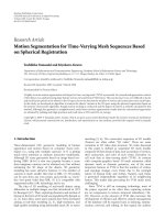
However, thermal-aware floorplanning is likely to be less
efficient when applied to CMPs as core-wide optimal deci-
sions will not necessarily be optimal when several cores are
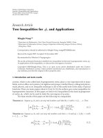
packed on the same chip. Referring to Figure 2(d), although
cores A and F are identical, their thermally optimal floorplan
is likely to be different due to the thermally different posi-
tions they have on the CMP. These differences in the optimal
floorplan are likely to increase as the number of on-chip cores
increases due to the fact that the number of thermally dif-
ferent locations increase with the number of on-chip cores.
Specifically, as Figures 2(a) to 2(d) show, for a CMP with n
2
cores, there will be (n/2·(n/2 +1))/2different possible
locations. A CMP with the majority of its cores being differ-
ent in terms of their floorplan would require a tremendous
design and verification effort making the optimal design pro-
hibitively expensive.
4. THERMAL-AWARE SCHEDULING
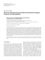
4.1. Scheduling
At any given time point, the operating system’s ready list con-
tains processes waiting for execution. At the same time, each
core of the CMP may be either idle or busy executing a pro-
cess (Figure 3). If idle cores exist, the operating system must
select the one on which the next process will be executed.
4.2. The ideal operation scenario
In the ideal case, each core has a constant temperature since
the processor was powered-on and therefore no temporal
temperature diversities exist. Additionally, this temperature
is the same among all cores eliminating spatial temperature
AA
AA
(a)
ABA
BCB
ABA
(b)
ABBA
BCCB
BCCB
ABBA
(c)
ABCBA
BDEDB
CEFEC
BDEDB
ABCBA
(d)
Figure 2: The thermally differ ent locations on the chip increase with
the number of cores. For a CMP with n
2
identical square cores, there
will be (
n/2·(n/2 +1))/2different locations.
diversities. The decrease of spatial and temporal temperature
diversities will have a positive effect on chip’s reliability. Of
course, this common operating temperature should be as low
as possible for lower power consumption, less need for cool-
ing, increased reliability, and increased performance. Finally,
the utilization of each core, that is, the fraction of time a core
is nonidle should be the same in order to avoid cases where a
core has “consumed its lifetime” whereas others have been ac-
tive for very short. Equal usage should also take into account
the thermal stress caused to each core by the applications it
executes. Specifically, the situation where a core has mainly
being executing temperature intensive applications whereas
others have mainly been executing moderate or low stress ap-
plications is unwanted. Equal usage among cores will result
in improving the chip-wide reliability.
4.3. Highly unwanted scenarios
Several application-execution scenarios that c an lead to
highly unwanted cases, such as, large per formance penalties
K. Stavrou and P. Trancoso 5
New
processes
···
Ready list
I/O processor
Cores state
Scheduler
Figure 3: Basic scheduling scheme in operating systems. Cores state array, shown as part of the scheduler, tracks the state of each core as busy
or idle.
or high thermal stress are discussed in this section. These sce-
narios do not necessarily describe the worse case, but are pre-
sented to show that temperature unaware scheduling can lead
to situations far from the ideal with consequences opposite
to those presented above. Simple thermal-aware scheduling
heuristics are shown to prevent such cases.
4.3.1. Scenario 1: large performance loss
As mentioned earlier, the most direct way the processor’s
temperature can affect its performance is due to more fre-
quent activation of DTM events, which occur each time the
temperature of the core exceeds a predefined threshold. The
higher the initial temperature of the core is, the easier it is
to reach this predefined threshold is. For the temperature
of a core to rise, its own heat generation (local) must be
larger than the heat it can dissipate to the ambient and to
the neighboring cores. However, a core can only dissipate
heat to its neighbors if they are cooler. The local heat genera-
tion is mainly determined by the application running on the
core which may be classified as “hot,” “moderate”,and“cool”
[4, 10, 34] depending on the heat it generates. Therefore, the
worsecaseforlargelossofperformanceistoexecuteahot
process on a hot core that resides in a hot neighborhood.
Let us assume that the CMP’s thermal snapshot (the
current temperature of its cores) is the one depicted in
Figure 4(a), and that a hot process is to be scheduled for ex-
ecution. Four cores are idle and thus candidate for execut-
ing the new process: C3, D4, E3, a nd E4. Although C3 is the
coolest core, it is the choice that will cause the largest per-
formance loss. C3 has reduced cooling ability due to being
surrounded by hot neighbors (C2, C4, B3, and D 3) and due
to not having free edges, that is, edges of the chip. As such, its
temperature will reach the threshold soon and consequently
activate a DTM event, leading to a per formance penalty.
A thermal-aware scheduler could identify the inappro-
priateness of C3 and notice that although E4 is not the coolest
idle core of the chip, it has two advantages: it resides in a
rather cool area and neighbors to the edge of the chip both
of which enhance its cooling ability. It would prefer E4 com-
paredtoE3asE4hastwoidleneighborsandcomparedtoD4
as it is cooler and has more efficient cooling.
4.3.2. Scenario 2: hotspot creation
The “best” way to create a hotspot, that is, an area on the chip
with very high thermal stress is to force very high tempera-
12345
E
D
C
B
A
33 38 31 32 35
34 35 40 36 30
38 40 30 40 35
36 35 40 40 34
35 36 37 36 35
(a)
12345
E
D
C
B
A
38 39 33 39 38
39 40 40 40 40
38 35 36 35 35
25 32 33 32 31
29 25 24 25 29
(b)
Figure 4: Thermal snapshots of the CMP. Busy cores are shown as
shaded. Numbers correspond to core’s temperature (
◦
C)abovethe
ambient.
ture on adjacent cores. This could be the result of running
hot applications on the cores and at the same time reducing
their cooling ability.
Such a case would occur if a hot application was executed
on core E3 of the CMP depicted in Figure 4(b). This would
decrease the cooling ability of its already very hot neighbors
(E2, E4, and D3). Furthermore, given that E3 is executing a
hot application and that it does not have any cooler neighbor,
it is likely to suffer from high temperature, soon leading to
the creation of a large hotspot at the bottom of the chip.
A thermal-aware scheduler would take into account the
impact such a scheduling decision would have, not only on
the core under evaluation but also on the other cores of the
chip, thus avoiding such a scenario.
4.3.3. Scenario 3: high spatial diversity
The largest spatial diversities over the chip appear when the
temperature of adjacent cores differs considerably. Chess like
scheduling (Figure 5) is the worse case scenario for spatial di-
versities as between each pair of busy and probably hot cores
an idle, thus cooler, one exists.
A thermal-aware scheduler would recognize this situa-
tion, as it is aware of the temperature of each core, and mod-
erate the spatial diversities.
4.3.4. Scenario 4: high temporal diversity
A core will suffer from high temporal diversities when the
workload it executes during consecutive intervals has op-
posite thermal behavior. Let us assume that the workload
6 EURASIP Journal on Embedded Systems
Distance
Te mp e ra tu re
Figure 5: Chess-like scheduling and its effect on spatial temperature
diversity. The chart shows the trend temperature is likely to follow
over the lines shown on the CMP.
consists of 2 hot and 2 moderate applications. A scenario that
would cause the worse case temporal diversities is the one de-
picted in Figure 6(a). In this scenario, process execution in-
tervals are fol lowed by an idle interval. Execution starts from
the two hot processes and continues with the moderate one
maximizing the temporal temperature diversity.
A thermal-aware scheduler that has information about
the thermal ty pe of the workload can efficiently avoid such
diversities (Figures 6(b) and 6(c)).
4.4. Thermal-aware scheduling on chip
multiprocessors
Thermal-Aware Scheduling (TAS) [27] is a mechanism that
aims to moderate or even eliminate the thermal-induced
problems of CMPs presented in the previous section. Specif-
ically, when scheduling a process for execution, TAS selects
one of the available cores based on the core’s “thermal state,”
that is, its temperature and cooling efficiency. TAS aims at
improving the performance and thermal profile of the CMP,
by reducing its temperature and consequently avoiding ther-
mal violation events.
4.4.1. TAS implementation or a real OS
Implementing the proposed scheme at the operating sys-
tem level enables commodity CMPs to benefit from TAS
without any need for microarchitectural changes. The need
for scheduling is inherent in multiprocessors operating sys-
tems and therefore, adding thermal awareness to it, by en-
hancing its kernel, will cause only negligible overhead for
schedulers of reasonable complexity. The only requirement
is an architecturally visible temperature sensor for each core,
something rather trivial given that the Power 5 processor
[18] already embeds 24 such sensors. Modern operating sys-
tems already provide functionality for accessing these sen-
sors through the advanced configuration and power inter-
face (ACPI) [41]. The overhead for accessing these sensors is
minimal and so we have not considered it in our experimen-
tal results.
4.4.2. Thermal-aware schedulers
In general, a thermal-aware scheduler, in addition to the
core’s availability takes into account its temperature and
other information regarding its cooling efficiency.
Although knowing the thermal type of the workload to
be executed can increase the efficiency of TAS, schedulers that
operate without this knowledge, as those presented below,
are shown by our experimental results to provide significant
benefits. Our study is currently limited to simple, stateless
scheduling algorithms w hich are presented next.
Coolest
ThenewprocessisassignedtotheCoolest idle core. This is
the simplest thermal-aware algorithm and the easiest to im-
plement.
Neighborhood
This algorithm calculates for each available core a cost func-
tion (equation (2)) and selects the core that minimizes it.
This cost function takes into consideration the following:
(i) temperature of the candidate core (T
c
),
(ii) average temperature of directly neighboring cores
(
T
DA
),
(iii) average temperature of diagonally neighboring cores
(
T
dA
),
(iv) number of nonbusy directly neighbor ing cores
(NB
DA
),
(v) the number of “free” edges of the candidate core (N
fe
).
Each parameter is given a different importance through
the a
i
weights. The value of these weights is determined stat-
ically through experimentation in order to match the char-
acteristics of the CMP. The rationale behind this algorithm
is that, the lower the temperature of the core’s neighborhood
is, the easier it will be to keep its temperature at low levels
due to the intercore heat exchange. Cores neighboring with
the edge of the chip are beneficial due to the increased heat
abduction r ate from the ambient,
Cost
= a
1
· T
c
+ a
2
· T
DA
+ a
3
· T
dA
+ a
4
· NB
DA
+ a
5
· N
fe
.
(2)
Threshold neighborhood
The Threshold Neighborhood algorithm uses the same cost
function as the Neighborhood algorithm, but schedules a pro-
cess for execution only if a good enough core exist. This good
enough threshold is a parameter of the algorithm. A core is
considered appropriate if its cost function is lower than this
K. Stavrou and P. Trancoso 7
Time
Temp er ature
HIHIMIM
(a)
Time
Temp er atu re
HMHM I I I
(b)
Time
Temp er atu re
HHMM I I I
(c)
Figure 6: Temporal temperature diversity. H stands for ‘hot” process, M for a process of moderate thermal stress, and I for an idle interval.
The charts show the trend temperature is likely to follow over the time. (a) The worse case temporal diversity scenario. (b) A scenario with
moderate temporal diversity. (c) The scenario that minimizes temporal diversity.
threshold (in contrast, when the neighborhood algorithm is
used, a process is scheduled no matter the value of the cost
function). This algorithm is nongreedy as it avoids schedul-
ing a process for execution on a core that is available but in a
thermally adverse state.
Although one would expect that the resulting underuti-
lization of the cores could lead to per formance degradation,
the experimental results showed that with careful tuning,
performance is improved due to the reduction of the number
of DTM events.
MST heuristic
The maximum scheduling temperature (MST) heuristic, is
not an algorithm itself but an option that can be used in com-
bination with any of the previously mentioned algorithms.
Specifically, MST prohibits scheduling a process for execu-
tion on idle cores when their temperature is higher than a
predefined threshold (MST
T
).
5. EXPERIMENTAL SETUP
To analyze the effect of thermal problems on the evolution of
the CMP architecture and to quantify the potential of TAS in
solving these issues, we conducted several experiments using
a specially developed simulator.
5.1. The simulated environment
At any given point in time, the operating system’s ready list
contains processes ready to be executed. At the same time,
each core of the CMP may be either busy executing a pro-
cess or idle. If idle cores exist, the operating system, using a
scheduling algorithm selects one such core and schedules on
it a process from the ready list. During the execution of the
simulation, new processes a re inserted into the ready list and
wait for their execution. When a process completes its execu-
tion, it is removed from the execution core, which is there-
after deemed as idle.
The heat produced during the operation of the CMP and
the characteristics of the chip define the temperature of each
core. For the simulated environment, the DTM mechanism
used is that of process migration. As such, when the temper-
ature of a core reaches a predefined threshold (45
◦
C above
the ambient), the process it executes is “migrated” to another
core. Each such migration event comeswithapenalty(mi-
gration penalty—DTM-P), which models the overheads and
performance loss it causes (e.g., invocation of the operating
system and cold c aches effec t).
5.2. The simulator
The simulator used is the Ther mal Scheduling SImulator for
Chip Multiprocessors (TSIC) [29], which has been developed
specially to study thermal-aware scheduling on chip mul-
tiprocessors. TSIC models CMPs with different number of
cores whereas it enables studies exploring several other pa-
rameters, such as the maximum allowed chip temperature,
chip utilization, chip size, migration events, and scheduling
algorithms.
5.2.1. Process model
The workload to be executed is the primary input for the sim-
ulator. It consists of a number of power traces, each one mod-
eling one process. Each point in a power trace represents the
average power consumption of that process during the corre-
sponding execution interval. Note that all intervals have the
same length in time. As the power consumption of a process
varies during its execution, a power trace is likely to consist
of different power consumption values for each point. The
lifetime of a process, that is, the total number of simulation
intervals that it needs to complete its execution, is defined as
the number of points in that power trace.
TSIC loads the workload to be executed in a workload
list and dynamically schedules each process to the available
cores. When the temperature of a core reaches a critical point
(DTM-threshold), the process running on it must be either
migrated to another core or suspended to allow the core to
cool. Such an event is called thermal violation event.Ifno
cores are available, that is, they are all busy or do not satisfy
the criteria for the MST heuristic of Threshold Neighborhood
algorithm, the process is moved back to the workload list and
will be rescheduled w hen a core becomes available.
8 EURASIP Journal on Embedded Systems
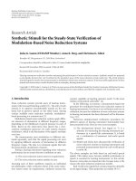
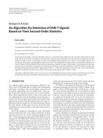
Figure 7: The main window of Thermal Scheduling SImulator for Chip Multiprocessors (TSIC).
Each time a process is to be assigned for execution, a
scheduling algorithm is invoked to select a core, among the
available ones, to which the process will be assigned for exe-
cution.
For the experiments presented in this paper, the work-
load used consists of 2500 synthetic randomly produced pro-
cesses with average lifetime equal to 100 simulation intervals
(1 millisecond per interval) and average power consump-
tion equal to 10 W. The rationale behind using a short av-
erage lifetime is to model the OS’s context-switch operation.
Specifically, each simulated process is to be considered as the
part of a real-world process during two consecutive context
switches.
5.2.2. The chip multiprocessor
TSIC uses a rather simplistic model for the chip’s floorplan
of the CMP. As depicted in Figure 7,eachcoreisconsidered
to cover a square area whereas the number of cores on the
chip is always equal to n
2
where n is the number of cores
in each dimension. In current TSIC implementation, cores
are assumed to be areas of uniform power consumption. The
area of the simulated chip is equal to 256 mm
2
(the default of
the Hotspot simulator [4]).
5.2.3. Thermal model
TSIC uses the thermal model of Hotspot [4] which has been
ported into the simulator. The floorplan is defined by the
number of cores and the size of the chip.
5.2.4. Metrics
During the execution of the workload, TSIC calculates the
total number of intervals required for its execution (Cycles),
the number of migrations (Migrations)aswellasseveral
temperature-related statistics listed below.
(i) Average T emperature: the Average T emperature repre-
sents the average temperature of all the cores of the chip dur-
ing the whole simulation period. The Average T emperature is
given by (3), where T
t
i, j
is the temperature of core i, j during
simulation interval t, S
T
is the total number of simulation
intervals, and n is the number of cores,
Average Temperature
= T =
S
T
t=0
n
i
=0
n
j
=0
T
t
i, j
n · S
T
. (3)
(ii) Average Spatial Diversity: the Spatial Diversity shows
the variation in the temperature among the cores at a given
time. The Average Spatial Diversity (equation (4)) is the av-
erage of the Spatial Diversity during the simulation period.
A value equal to zero means that a ll cores of the chip have
the same temperature a t the same time, but possibly differ-
ent temper ature at different points in time. The larger this
value is, the grater the variability is. In the Average Spatial
Diversity equation, T
t
i, j
is the temperature of core i, j during
simulation interval t,
T
t
= 1/n
2
·
n
i=0
n
j=0
T
t
i, j
is the aver-
age chip temperature during simulation interval t, S
T
is the
total number of simulation intervals, and n is the number of
cores,
Average Spatial Diversity
=
S
T
t=0
n
i
=0
n
j
=0
T
t
i, j
− T
t
n · S
T
.
(4)
(iii) Average Temporal Diversity: the Average Temporal Di-
versity is a metric of the variation of the average chip temper-
ature, across all cores, and is defined by (5). In the Average
Temporal Diversit y equation T
t
i, j
is the temperature of core
i, j during simulation interval t,
T
t
= 1/n
2
·
n
i=0
n
j=0
T
t
i, j
K. Stavrou and P. Trancoso 9
is the average chip temperature during simulation interval t,
T is the average chip temperature as defined by (3), S
T
is the
total number of simulation intevals, and n is the number of
cores,
Average Temporal Diversity
=
S
T
i=0
S
T
j=0
T
t
− T
n · S
T
.
(5)
(iv) Efficiency:efficiency is a metric of the actual perfor-
mance the multiprocessor achieves in the presence of thermal
problems compared to the potential offered by the CMP. Effi-
ciency is defined by (6) as the ratio between the time required
for the execution of the workload (Workload Execut ion Time)
and the time it would require if no thermal violation events
existed (Potential Execution Time,(7)). The maximum value
for the Efficiency metric is 1 and represents full utilization of
the available resources,
Efficiency
=
Potential Execution Time
Workload Execution Time
,(6)
Potential Execution Time
=
#processes
n=1
Lifetime
Process
n
Number of Cores
.
(7)
5.2.5. Scheduling algorithms
For the experimental results presented in Section 6,all
threshold values for the scheduling algorithms, the a
i
fac-
tors in (2), the MST-T, and the “Threshold Neighborhood,”
have been statically determined through experimentation.
Although adaptation of these threshold values could be done
dynamically, this would result in an overhead for the sched-
uler of the operating system. We are however currently study-
ing these issues.
6. RESULTS
6.1. Thermal behavior and its implications
for future CMPs
In this section we present the thermal behavior and its impact
on the performance for future CMP configurations which are
based on the technology evolution. This leads to chips of de-
creasing area and/or more cores per chip. For the results pre-
sented, we assumed that the CMPs are r unning an operating
system that supports a minimal overhead thermal scheduling
algorithm such as Coolest (baseline algorithm for this study).
Consequently these results are also an indication of the ap-
plicability of simple thermal scheduling policies.
6.1.1. Trend 1: decreasing the chip size
As mentioned earlier, technology improvements and feature
size shrink will allow the trend of decreasing the chip size
to continue. Figure 8(a) depicts the effect of this chip size
decrease while keeping the consumed power constant for a
CMP with 16 cores. The results clearly show the negative ef-
fect of chip’s area decrease on the average temperature and
1600 784 529 400 289 256 225 196 169 144
Chip size (mm
2
)
0
0.2
0.4
0.6
0.8
1
1.2
Efficiency
0
10
20
30
40
50
Te m p e ra t ur e
Efficiency
Te m p e ra t ur e
(a)
1600 784 529 400 289
Chip size (mm
2
)
0
1
2
3
4
5
6
Diversities
Te m p o ral d ive rs ity
Spatial diversity
(b)
Figure 8: (a) Efficiency and temperature (
◦
C above the ambient)
and (b) spatial and temporal diversities for different chip sizes.
the efficiency of the multiprocessor. This is explained by the
fact that the ability of the chip to cool by vertically dissipating
heat to the ambient is directly related to its area (Section 3.1).
Lower cooling ability leads to higher temperature, which
in turn leads to increased number of migrations, and conse-
quently to significant performance loss. The reason for which
the temperature only asymptotically approximates 45
◦
Cis
related to the protection mechanism used (process migra-
tion) which is triggered at 45
◦
C. Notice that the area of typi-
cal chips today does not exceed 256 mm
2
, which is the point
beyond which it is possible to observe considerable perfor-
mance degradation. A migration penalty (DTM-P) of one
interval is used for these experiments. This value is small
compared to what would apply in a real world system and
consequently these charts present an optimistic scenario.
Another unwanted effect is related to the spatial and tem-
poral diversities, which also become worse for smaller chips
(Figure 8(b)) and is justified mainly by the higher operating
temperatures. Notice that in this chart we limit the chip size
range to that for which no mig rations exist in order to ex-
clude from the trend line the effect of migrations.
6.1.2. Trend 2: increasing the number of cores
As explained in Section 3.2, due to thermal limitations, the
throughput potential offered by the increased number of
cores cannot be exploited unless the size of the CMP is
scaled proportionally. Figure 9 depicts the efficiency and
10 EURASIP Journal on Embedded Systems
4163664
Number of cores
0
0.2
0.4
0.6
0.8
1
Efficiency
Utilization 50%
Utilization 80%
Utilization 100%
(a)
4163664
Number of cores
0
10
20
30
40
50
Te m p e ra t ur e
Utilization 50%
Utilization 80%
Utilization 100%
(b)
4163664
Number of cores
0
25
50
75
100
125
150
×10
2
Execution time
Utilization 50%
Utilization 80%
Utilization 100%
(c)
4163664
Number of cores
0
1
2
3
4
Slowdown
Utilization 50%
Utilization 80%
Utilization 100%
(d)
Figure 9: (a) Efficiency (b) temperature (
◦
C above the ambient) (c) workload execution time (in terms of simulation intervals) (d) slowdown
orienting from temperature issues for CMPs with different number of cores and different utilization points.
temperature for CMPs with different number of cores (4, 16,
36, and 64) for three different utilization points (50%, 80%,
and 100%). Utilization shows the average fraction of cores
that are ac tive at any time point and models the execution
stress of the multiprocessor.
The efficiency of the different CMP configurations stud-
ied is depicted in Figure 9(a). The decrease in efficiency with
the increase in the number of on-chip cores is justified by the
decrease in the per-core area and consequently of the verti-
cal cooling capability. The increased utilization also decreases
the cooling capabilities of cores but this is related to the lat-
eral heat t ransfer path. Specifically, if a neighboring core is
busy, and thus most likely hot, cooling through that direc-
tion is less efficient.Intheworsescenario,acorewillre-
ceive heat from its neighbors and instead of cooling, it will
get hotter. Both factors have a negative effect on temperature
(Figure 9(b)) and consequently in the number of migration
events, which is the main reason for performance loss. It is
relevant to notice that for the 36- and 64-core CMPs the aver-
age temperature is limited by the maximum allowed thresh-
old, which has been set to 45
◦
C for these experiments.
The workload execution time for the different CMP con-
figurations studied is depicted in Figure 9(c)). For the 4-core
CMP, higher utilization leads to a near proportional speedup,
which is significantly smaller for the 16-core CMP and al-
most diminishes for multiprocessors with more cores. This
indicates the constrain thermal issues pose on the scalability
offered by the CMP’s architecture. It is relevant to notice that
for the 100% utilization point, the 64-core chip has almost
the same performance as the 16-core CMP. This behavior is
justified by the large number of migr ation events suffered by
the large scale CMPs.
Figure 9(d) displays the slowdown of each configuration
due to temperature related issues taking the utilization into
consideration, that is, if a configuration with utilization 50%
executes the workload in 2X cycles where the same configu-
ration with 100% utilization executes it in X cycles, the for-
mer is considered to have zero slowdown. The results em-
phasize the limitations posed by temperature issues on fully
utilizing the available resources. Notice that these limitations
worsen as the available resources increase.
Finally, Figure 10 depicts the spatial and temporal diver-
sities of the CMP configurations studied, when utilization is
equal to 100%. Both diversities are shown to worsen when
more cores coexist on the chip. This is not only due to the
higher temperature but also due to variability caused by the
larger number of on-chip cores.
6.2. Optimization 1: thermal threshold
The results from the previous section showed a significant
drop in performance as the maximum operating temperature
K. Stavrou and P. Trancoso 11
4 9 16 25 36 49 64
Number of cores
0
0.5
1
1.5
2
Spatial diversity
(a)
4 9 16 25 36 49 64
Number of cores
0
2
4
6
8
10
Te m p o ral d ive rs ity
(b)
Figure 10: (a) Spatial and (b) temporal diversity as the number of
on-chip cores increases.
is reached. To avoid this performance degradation, we pro-
pose to enhance the basic Thermal-aware scheduling policy
(Coolest) by using a threshold on the core’s temperature. This
is what we named the Coolest + MST scheduling scheme, that
is, a process is executed on the coolest available core only if a
core with temperature lower than N
◦
C exists. In our case, we
use 40
◦
C as the threshold value (MST-T), that is, five degrees
lower than the maximum allowed temperature. The goal for
these experiments is to show how, Coolest + M ST,isableto
improve the performance by reducing the number of migra-
tions. In addition, we set the DTM-Penalty to zero, which is
the reason why we will not present performance results.
Table 1 presents the number of migrations and the aver-
age temperature for the execution scenarios mentioned be-
fore. As can be seen from the results, the Coolest + MST
heuristic is able to significantly decrease the number of mi-
gration events. The potential of this algorithm increases with
the number of cores. This is a first-class indication that per-
formance improvement can be achieved. At the same time,
this TAS scheme decreases the average chip temperature by
approximately 2
◦
C for the 16-core and 2.5
◦
C for the 25-core
CMP.
Figure 11 depicts the number of migrations and tem-
perature of CMPs with different number of cores as the
MST-Threshold (MST-T) ranges from 40
◦
Cto45
◦
C. Note
that when MST-T is equal to the DTM-threshold (DTM-T)
(45
◦
C), scheduling is the same as w h at would apply without
MST (Coolest).
As depicted in Figure 11(a) for both the 16-core and 25-
core CMP, the number of migrations increases with the MST-
T. This is due to the fact that cores with very high tempera-
Table 1: Number of migrations and average temperature (
◦
C)
above the ambient for CMPs of different number of cores for two
scheduling schemes.
Number of migrations Te mpe ra ture (
◦
C)
Number of
cores
Coolest Coolest + MST Coolest Coolest + MST
4 0011.38 11.38
9
0023.63 23.63
16
1193 6 38.74 36.88
25
109 733 1222 42.58 39.94
40 41 42 43 44 45
MST threshold
1.E +00
1.E +01
1.E +02
1.E +03
1.E +04
1.E +05
Number of migrations (log scale)
16 cores
25 cores
(a)
40 41 42 43 44 45
MST threshold
32
34
36
38
40
42
44
Te m p e ra t ur e
16 cores
25 cores
(b)
Figure 11: (a) Number of migrations graphed in a logarithmic scale
and (b) average chip temperature (
◦
C above the ambient) versus
MST-T.
ture are allowed to be used. The same trend stands for the
average temperature of the chip (Figure 11(b)), which justi-
fies what is observed for migrations.
No performance results are presented for this experiment
as the DTM-Penalty value has been set to be equal to 1 in-
terval only. As such, its impact on performance is minimal.
However, as mentioned earlier, in a real-world system the
DTM-Penalty will be significantly larger.
When DTM events are penalized, execution using the
Coolest policy may not complete. If the scheduling algorithm
12 EURASIP Journal on Embedded Systems
is greedy in that it tries to fully utilize the available re-
sources no matter their thermal state, a scenario described
by a vicious-circle of continued process-migrations is possi-
ble. Such a scenario appears when cores with very high tem-
perature are used and at the same time, the average tempera-
ture of the chip is close to DTM-T. For example, this scenario
happens when executing the experimental workload on a 36-
core CMP with Coolest.
6.3. Optimization 2: neighborhood awareness
The results from the previous section showed that adding a
Threshold to the simple thermal-aware scheduling (Coolest)
policy can significantly decrease the number of migration
events. Nevertheless, the Coolest + MST algorithm uses lo-
cal information to make the scheduling decisions, that is, it
considers only the temperature of the candidate cores.
In this section, we present the results for an algorithm
that t akes into consideration not only the temperature of
the candidate cores but also the temperatures of all the sur-
rounding or neighboring cores. We p resented previously, in
Section 4.4, two algorithms that use this information, the
Neighborhood and the Threshold Neighborhood. The results
presented in this section are for the Threshold Neighborhood
as its p erformance is much better compared to the simple
Neighborhood.
As we have not yet completely tuned the Threshold Neigh-
borhood algorithm, we present results only for a single setup
of a CMP with 16 cores and 100% utilization. Figure 12(a)
depicts the number of migrations for the two algorithms un-
der evaluation (Threshold Neighborhood and Coolest + MST),
for different DTM-Penalties.
The number of migration events suffered by the Thresh-
old Ne ighborhood algorithm is always smaller compared to
those of the Coolest + MST. For the Coolest + MST algorithm,
this number of migrations increases with the DTM-Penalty
as the additional time required for the execution of the work-
load worsens the already problematic thermal state of the
CMP. On the other hand, for the Threshold Neighborhood al-
gorithm the number of migrations decrease with the DTM-
Penalty. This shows the ability of the algorithm to adapt to
the different DTM-Penalty values. Specifically, as this penalty
increases, the algorithm becomes more strict when evaluat-
ing the thermal appropriateness of a core.
It must be noted here that the parameters of the Thresh-
old Neighborhood algorithm are not the same for all situa-
tions. As the migration penalty increases, the configuration
that performs better is the one that has smaller weight for the
temperature of the candidate core and larger weight for the
number of nonbusy directly adjacent cores (See (2)). How-
ever, when the migration penalty is small, a conservative s e-
lection for execution cores is not desired as the effect of mi-
grations is less important.
Figure 12(b) depicts the execution time of the experi-
mental workload for the different scenarios studied. The per-
formance of the Coolest + MST algorithm worsens as the
DTM Penalty increases mainly due to two reasons. T he first
is related to the increase of migration events whereas the sec-
5101520
DTM penalty
0
2
4
6
8
10
12
14
×10
3
Number of migrations
Coolest with MST
Threshold neighborhood
(a)
5101520
DTM penalty
0
2
4
6
8
10
×10
3
Execution time
Coolest with MST
Threshold neighborhood
(b)
5101520
DTM penalty
35
36
37
38
39
40
41
42
43
Te m p e ra t ur e
Coolest with MST
Threshold neighborhood
(c)
Figure 12: (a) Number of migrations, (b) temperature (
◦
Cabove
the ambient), and (c) execution time (number of simulation inter-
vals) for different DTM-Penalties and scheduling schemes.
ond to the fact that each migration has a larger cost. In con-
trast, the performance of Threshold Neighborhood algorithm
is almost constant. This is due to the ability of the algorithm
to decrease the number of migrations it suffers, as their cost
increases with the migration penalty.
K. Stavrou and P. Trancoso 13
5101520
DTM penalty
0
5
10
15
20
25
30
×10
3
Execution time
Coolest
Coolest with MST
Threshold neighborhood
Figure 13: Execution time for different CMP scheduling schemes
and DTM-Penalties.
Finally, Figure 12(c) depicts the average temperature of
the chip for the different configurations studied. It is obvious
that the Threshold Neighborhood algorithm manages not only
to increase performance but also to decrease the temperature
of the chip. This was expected, as only when the chip has
better temperature characteristics, migration events can be
controlled.
This exploration clearly shows that trying to fully uti-
lize the available resources without taking into consideration
the thermal issues may significantly affect perfor mance. An-
other conclusion is that it is often beneficial to be conserva-
tive on utilizing the on-chip resources as this will allow better
cooling, will decrease the number of migrations, and conse-
quently enhance performance.
6.4. Summary
In the previous sections, we showed the performance im-
provements that may be achieved by two optimizations to
the basic TAS algorithm (Coolest). On the one hand, Coolest
+MSTuses a threshold to reduce the number of migrations.
On the other hand, Threshold Neighborhood uses local and
information about the surrounding cores to take the schedul-
ing decisions. In addition to reducing the number of migra-
tions, this algorithm has also the potential to achieve a better
chip-wide thermal behavior. A simple comparison between
the three TAS algorithms is presented in Figure 13. This Fig-
ure depicts the execution time for the three algorithms for
different DTM penalty values on a 16-core CMP.
The results in Figure 13 show that Coolest is intolerant to
the increase of the DTM penalty, resulting in large perfor-
mance loss. This is due to the larger number of migrations
compared with the other algorithms. The Coolest + MST per-
forms well for smaller values of DTM penalty. Nevertheless,
it is possible to observe that the execution time almost dou-
bled for Coolest + MST when the penalty increased from
15 to 20. In contrast with the previous two algorithms, for
Threshold Neighbor hood the execution time is not affected by
the increase in the DTM penalty resulting in almost no per-
formance degradation. As such, we a re led to conclude that
the Threshold Neighborhood is the most stable TAS algorithm
that achieves the best overall results.
7. CONCLUSIONS
In this paper, we have shown that packing a large num-
ber of cores onto the same chip reduces the per-core cool-
ing ability comparing to a single chip microprocessor further
increasing the temperature-induced problems. Additionally,
we have presented several scenarios that result in excessive
thermal stress or significant performance loss due to insuf-
ficient heat dissipation. In order to minimize or eliminate
these problems, we propose thermal-aware scheduler algo-
rithms that take into account the thermal state of the CMP
while assig ning processes to cores. We have shown that such
a scheduler can decrease or even avoid high-thermal-stress
scenarios, at the same time significantly improving the per-
formance.
REFERENCES
[1] V. Agarwal, M. S. Hrishikesh, S. W. Keckler, and D. Burger,
“Clock rate versus IPC: the end of the road for conventional
microarchitectures,” in Proceedings of the 27th Annual Inter-
national Symposium on Computer Architecture (ISCA ’00),pp.
248–259, ACM Press, Vancouver, BC, Canada, June 2000.
[2] K. Olukotun, B. A. Nayfeh, L. Hammond, K. Wilson, and K.
Chang, “The case for a single-chip multiprocessor,” in Proceed-
ings of the 7th International Conference on Architectural Support
for Programming Languages and Operating Systems (ASPLOS
’96), pp. 2–11, ACM Press, Cambridge, Mass, USA, October
1996.
[3] T. Mudge, “Power: a first-class architectural design constraint,”
Computer, vol. 34, no. 4, pp. 52–58, 2001.
[4] K.Skadron,M.R.Stan,W.Huang,S.Velusamy,K.Sankara-
narayanan, and D. Tarjan, “Temperature-aware microarchi-
tecture: extended discussion and results,” Tech. Rep. TR-
CS-2003-08, University of Virginia, Charlottesville, Va, USA,
2003.
[5] R. Viswanath, V. Wakharkar, A. Watwe, and V. Lebonheur,
“Thermal performance challenges from silicon to systems,” In-
tel Technology Journal, vol. 4, no. 3, p. 16, 2000.
[6] S. H. Gunther, F. Binns, D. M. Carmean, and J. C. Hall, “Man-
aging the impact of increasing microprocessor power con-
sumption,” Intel Technology Journal, vol. 5, no. 1, p. 9, 2001.
[7] W. Liao and L. He, “Coupled power and ther mal simulation
with active cooling,” in Proceedings of the 3rd International
Workshop on Power-Aware Computer Systems (PACS ’03),
vol. 3164 of Lecture Notes in Computer Science, pp. 148–163,
San Diego, Calif, USA, December 2003.
[8] A. Dhodapkar, C. H. Lim, G. Cai, and W. R. Daasch,
“TEM
2
P
2
EST: a thermal enabled multi-model power/
performance ESTimator,” in Proceedings of the 1st Interna-
tional Workshop on Power-Aware Computer Systems-Revised
Papers (PACS ’00), pp. 112–125, Cambridge, Mass, USA,
November 2000.
[9] R.Mahajan,K.Brown,andV.Atluri,“Theevolutionofmi-
croprocessor packaging,” Intel Technology Journal, p. 10, 2001.
14 EURASIP Journal on Embedded Systems
[10] Y. Li, D. Brooks, Z. Hu, and K. Skadron, “Performance, energy,
and thermal considerations for SMT and CMP architectures,”
in Proceedings of the 11th International Symposium on High-
Performance Computer Architecture (HPCA ’05), pp. 71–82,
San Francisco, Calif, USA, February 2005.
[11] D. Genossar and N. Shamir, “Intel pentium M processor:
power estimation, budgeting, optimization and validation,”
Intel Technology Journal, vol. 7, no. 2, pp. 44–49, 2003.
[12] J. Mooref, J. Chasef, P. Ranganathanf, and R. Sharmaf, “Mak-
ing scheduling “cool”: temperature-aware workload place-
ment in data centers,” in Proceedings of the USENIX Annual
Technical Conference, pp. 61–75, Anaheim, Calif, USA, April
2005.
[13] S. Heo, K. Barr, and K. Asanovi
´
c, “Reducing power density
through activity migration,” in Proceedings of the International
Symposium on Low Power Electronics and Design (ISLPED ’03),
pp. 217–222, Seoul, South Korea, August 2003.
[14] Z. Lu, W. Huang, S. Ghosh, J. Lach, M. Stan, and K. Skadron,
“Analysis of temporal and spatial temperature gradients for
IC reliability,” Tech. Rep. CS-2004-08, University of Virginia,
Charlottesville, Va, USA, March 2004.
[15] Z. Lu, J. Lach, M. Stan, and K. Skadron, “Banking chip life-
time: opportunities and implementation,” in Proceedings of the
1st Workshop on High Performance Computing Reliability Issues
(HPCRI ’05), San Francisco, Calif, USA, February 2005.
[16] C. Bailey, “Modelling the effectoftemperatureonproductre-
liability,” in Proceedings of 19th Annual IEEE Semiconductor
Thermal Measurement and Management Symposium (SEMI-
THERM ’03), pp. 324–331, San Jose, Calif, USA, March 2003.
[17] R. Mukherjee, S. O. Memik, and G. Memik, “Temperature-
aware resource allocation and binding in high-level synthe-
sis,” in Proceedings of the 42nd Design Automation Conference
(DAC ’05), pp. 196–201, ACM Press, Anaheim, Calif, USA,
June 2005.
[18] R. Kalla, B. Sinharoy, and J. M. Tendler, “IBM Power5 chip: a
dual-core multithreaded processor,” IEEE Micro, vol. 24, no. 2,
pp. 40–47, 2004.
[19] P. Kongetira, K. Aingar an, and K. Olukotun, “Niagara: a 32-
way multithreaded Sparc processor,” IEEE Micro, vol. 25, no. 2,
pp. 21–29, 2005.
[20] Intel, “Intel Pentium D Processor Product Information,” 2006,
/>d/.
[21] AMD, “AMD Athlon 64X2 Dual-Core Processor,” 2006,
/>[22] R. Sasanka, S. V. Adve, Y K. Chen, and E. Debes, “The en-
ergy efficiency of CMP vs. SMT for multimedia workloads,”
in Proceedings of the 18th Annual International Conference on
Supercomputing (ICS ’04), pp. 196–206, Saint-Malo, France,
June-July 2004.
[23] E. Debes, “Recent changes and future trends in general pur-
pose processor architectures to support image and video ap-
plications,” in Proceedings of IEEE International Conference
on Image Processing (ICIP ’03), vol. 3, pp. 85–88, Barcelona,
Spain, September 2003.
[24] F. Mombers and D. Mlynek, “Multithreaded multimedia pro-
cessor merging on-chip multiprocessors and distributed vec-
tor pipelines,” in Proceedings of IEEE International Symposium
on Circuits and Systems (ISCAS ’99), vol. 4, pp. 287–290, Or-
lando, Fla, USA, May-June 1999.
[25] J. Goodacre, “Understanding the Options for Embedded Mul-
tiprocessing,” 2003, TechOnLine: />community/tech
group/soc/tech paper/29359.
[26] Intel, “Intel Pentium D Processor Product Information,” 2006,
/>d/.
[27] K. Stavrou and P. Trancoso, “Ther mal-aware scheduling: a so-
lution for future chip multiprocessors thermal problems,” in
Proceedings of the 9th EUROMICRO Conference on Digital Sys-
tem Design: Architectures, Methods and To ols (DSD ’06),pp.
123–126, Dubrovnik, Croatia, August-September 2006.
[28] E. Grochowski, R. Ronen, J. Shen, and H. Wang, “Best of b oth
latency and throughput,” in Proceedings of IEEE International
Conference on Computer Design: VLSI in Computers and Pro-
cessors (ICCD ’04), pp. 236–243, San Jose, Calif, USA, October
2004.
[29] K. Stavrou and P. Trancoso, “TSIC: thermal scheduling simu-
lator for chip multiprocessors,” in Proceedings of the 10th Pan-
hellenic Conference on Informatics (PCI ’05), vol. 3746 of Lec-
ture Notes in Computer Science, pp. 589–599, Volos, Greece,
November 2005.
[30] P. I. P
´
enzes, M. Nystr
¨
om, and A. J. Martin, “Transistor siz-
ing of energy-delay-efficient circuits,” in Proceedings of the
8th ACM/IEEE International Workshop on Timing Issues in the
Specification and Synthesis of Digital Systems (TAU ’02),pp.
126–133, Monterey, Calif, USA, December 2002.
[31] J. Ebergen, J. Gainsley, and P. Cunningham, “Transistor siz-
ing: how to control the speed and energy consumption of a
circuit,” in Proceedings of the 10th International Symposium
on Advanced Research in Asynchronous Circuits and Systems
(ASYNC ’04), vol. 10, pp. 51–61, Crete, Greece, April 2004.
[32] R. Balasubramonian, D. Albonesi, A. Buyuktosunoglu, and
S. Dwarkadas, “Memory hierarchy reconfiguration for energy
and performance in general-purpose processor architectures,”
in Proceedings of the 33rd Annual IEEE/ACM International
Symposium on Microarchitecture (MICRO ’00), pp. 245–257,
ACM Press, Monterey, Calif, USA, December 2000.
[33] S. Manne, A. Klauser, and D. Grunwald, “Pipeline gating:
speculation control for energy reduction,” in Proceedings of
the 25th Annual International Sy mposium on Computer Archi-
tecture (ISCA ’98), pp. 132–141, Barcelona, Spain, June-July
1998.
[34] Y. Han, I. Koren, and C. A. Moritz, “Temperature aware floor-
planning,” in Proceedings of the 2nd Workshop on Temperature-
Aware Computer Systems (TACS ’05), Madison, Wis, USA, June
2005.
[35] R. McGowen, C. A. Poirier, C. Bostak, et al., “Power and tem-
perature control on a 90-nm Itanium family processor,” IEEE
Journal of Solid-State Circuits, vol. 41, no. 1, pp. 229–237, 2006.
[36] J. Donald and M. Martonosi, “Techniques for multicore ther-
mal management: classification and new exploration,” in Pro-
ceedings of the 33rd International Symposium on Computer Ar-
chitecture (ISCA ’06), pp. 78–88, Boston, Mass, USA, June
2006.
[37] NIST/SEMATECH, Assessing Product Reliability, Chapter 8,
e-Handbook of Statistical Methods, />div898/handbook/.
[38] J. Srinivasan, S. V. Adve, P. Bose, J. Rivers, and C K. Hu,
“RAMP: a model for reliability aware microprocessor design,”
IBM Research Report RC23048, p. 26, IBM, White Plains, NY,
USA, 2003.
[39] W L. Hung, Y. Xie, N. Vijaykrishnan, M. Kandemir, and M.
J. Irwin, “Thermal-aware task allocation and scheduling for
embedded systems,” in Proceedings of the Conference on Design,
Automation and Test in Europe (DATE ’05), vol. 2, pp. 898–899,
IEEE Computer Society, Munich, Germany, March 2005.
K. Stavrou and P. Trancoso 15
[40] P. Rosinger, B. Al-Hashimi, and K. Chakrabarty, “Rapid gener-
ation of thermal-safe test schedules,” in Proceedings of the Con-
ference on Design, Automation and Test in Europe (DATE ’05),
vol. 2, pp. 840–845, IEEE Computer Society, Munich, Ger-
many, March 2005.
[41] ACPI, “Advanced Configuration and Power Interface,” 2006,
o/.