Báo cáo hóa học: " Research Article A Systematic Approach to Design Low-Power Video Codec Cores" doc
Bạn đang xem bản rút gọn của tài liệu. Xem và tải ngay bản đầy đủ của tài liệu tại đây (1.61 MB, 14 trang )
Hindawi Publishing Corporation
EURASIP Journal on Embedded Systems
Volume 2007, Article ID 64569, 14 pages
doi:10.1155/2007/64569
Research Article
A Systematic Approach to Design Low-Power
Video Codec Cores
Kristof Denolf,
1
Adrian Chirila-Rus,
2
Paul Schumacher,
2
Robert Turney,
2
Kees Vissers,
2
Diederik Verkest,
1, 3, 4
and Henk Corporaal
5
1
D6, IMEC, Kapeldreef 75, 3001 Leuven, Belgium
2
Xilinx Inc., 2100 Logic Drive, San Jose, CA 95124-3400, USA
3
Department of Electrical Engineering, Katholieke Universiteit Leuven (KUL), 3001 Leuven, Belgium
4
Department of Electrical Engineering, Vrije Universiteit Brussel (VUB), 1050 Br ussel, Belgium
5
Faculty of Electrical Engineering, Technical University Eindhoven, Den Dolech 2, 5612 AZ Eindhoven, The Netherlands
Received 2 June 2006; Revised 7 December 2006; Accepted 5 March 2007
Recommended by Leonel Sousa
The higher resolutions and new functionality of video applications increase their throughput and processing requirements. In
contrast, the energy and heat limitations of mobile devices demand low-power video cores. We propose a memor y and communi-
cation centric design methodology to reach an energy-efficient dedicated implementation. First, memory optimizations are com-
bined with algorithmic tuning. Then, a partitioning exploration introduces parallelism using a cyclo-static dataflow model that
also expresses implementation-specific aspects of communication channels. Towards hardware, these channels are implemented
as a restricted set of communication primitives. They enable an automated RTL development strategy for rigorous functional ver-
ification. The FPGA/ASIC design of an MPEG-4 Simple Profile video codec demonstrates the methodology. The video pipeline
exploits the inherent functional parallelism of the codec and contains a tailored memory hierarchy with burst accesses to external
memory. 4CIF encoding at 30 fps, consumes 71 mW in a 180 nm, 1.62 V UMC technology.
Copyright © 2007 Kristof Denolf et al. This is an open access article distributed under the Creative Commons Attribution License,
which permits unrestricted use, distribution, and reproduction in any medium, provided the original work is properly cited.
1. INTRODUCTION
New video appliances, like cellular videophones and digi-
tal cameras, not only offer higher resolutions, but they also
support the latest coding/decoding techniques utilizing ad-
vanced video tools to improve the compression performance.
These two trends continuously increase the algorithmic com-
plexity and the throughput requirements of video coding ap-
plications and complicate the challenges to reach a real-time
implementation. Moreover, the limited battery power and
heat dissipation restrictions of portable devices create the de-
mand for a low-power design of multimedia applications.
Their energy efficiency needs to be evaluated from the system
including the off-chip memory, as its bandwidth and size has
a major impact on the total power consumption and the final
throughput.
In this paper, we propose a dataflow oriented design ap-
proach for low-power block based video processing and ap-
ply it to the design of a MPEG-4 part 2 Simple Profile video
encoder.Thecompleteflowhasamemoryfocusmotivated
by the data dominated nature of video processing, that is, the
data transfer and storage has a major impact on the energy
efficiency and on the achieved throughput of an implementa-
tion [1–3]. We concentrate on establishing the overall design
flow and show how previously published design steps and
concepts can be combined with the parallelization and ver-
ification support. Additionally, the barrier to the high energy
efficiency of dedicated hardware is lowered by an automated
RTL development and verification environment reducing the
design time.
The energy efficiency of a real-time implementation de-
pends on the energy spent for a task and the time bud-
getrequiredforthistask.Theenergydelayproduct[4]ex-
presses both aspects. The nature of the low-power techniques
and their impact on the energy delay product evolve while
the designer goes through the proposed design flow. The
first steps of the design flow are generic (i.e., applicable to
other types of applications than block-based video process-
ing). They combine memory optimizations and algorithmic
tuning at the high-level (C code) w h ich improve the data
2 EURASIP Journal on Embedded Systems
locality and reduce the computations. These optimizations
improve both factors of the energy delay product and prepare
the partitioning of the system. Parallelization is a well-known
technique in low-power implementations: it reduces the de-
lay per task while keeping the energy per task constant. The
partitioning exploration step of the design flow uses a Cyclo-
Static DataFlow (CSDF, [5]) model to support the buffer ca-
pacities sizing of the communication channels between the
parallel tasks. The queues implementing these communica-
tion channels restrict the scope of the design flow to block
based processing as they mainly support transferring blocks
of data. The lowest design steps focus on the development
of dedicated hardware accelerators as they enable the best
energy-efficiency [6, 7] at the cost of flexibility. Since spe-
cialized hardware reduces the overhead work a more general
processor needs to do, both energy and performance can be
improved [4]. For the MPEG-4 Simple Profile video encoder
design, applying the proposed strategy results in a fully ded-
icated video pipeline consuming only 71 mW in a 180 nm,
1.62 V technology when encoding 4CIF at 30 fps.
This paper is organized as follows. After an overview of
related work, Section 3 introduces the methodology. The re-
maining sections explain the design steps in depth and how
to apply them on the design of a MPEG-4 Simple Profile
encoder. Section 4 first int roduces the video encoding al-
gorithm, and then sets the design specifications and sum-
marizes the high-level optimizations. The resulting localized
system is partitioned in Section 5 by first describing it as a
CSDF model. The interprocess communication is realized by
a limited set of communication primitives. Section 6 devel-
ops for each process a dedicated hardware accelerator using
the RTL development and verification strategy to reduce the
design time. The power efficiency of the resulting video en-
coder core is compared to state of the art in Section 7.The
conclusions are the last sect ion of the paper.
2. RELATED WORK
The design experiences of [8] on image/video processing in-
dicate the required elements in rigorous design methods for
the cost efficient hardware implementation of complex em-
bedded systems: higher abstraction levels and extended func-
tional verification. An extensive overview of specification,
validation, and synthesis approaches to deal with these as-
pects is given in [9]. The techniques for power aware system
design [10] are grouped according to their impact on the en-
ergy delay product in [4]. Our proposed design flow assigns
them to a design step and identifies the appropriate models.
It combines and extends known approaches and techniques
to obtain a low-power implementation.
The Data Transfer and Storage Exploration (DTSE) [11,
12] presents a set of loop and dataflow transformations, and
memory organization tasks to improve the data localit y of
an application. In this way, the dominating memory cost
factor of multimedia processing is tackled at the high level.
Previously, we combined this DTSE methodology with algo-
rithmic optimizations complying with the DTSE rules [13].
This paper also makes extensions at the lower levels with a
partitioning exploration matched towards RTL development.
Overall, we now have a complete design flow dealing with the
dominant memory cost of video processing focused on the
development of dedicated cores.
Synchronous Dataflow (SDF, [14]) and Cyclo-Static
Dataflow (CSDF, [5]) models of computation match well
with the dataflow dominated behavior of video processing.
They are good abstraction means to reason on the parallelism
required in a high-throughput implementation. Other works
make extensions to (C)SDF to describe image [15]andvideo
[16, 17] applications. In contrast, we use a specific interpreta-
tion that preserves all analysis potential of the model. Papers
describing RTL code generation from SDF graphs use either
a centralized controller [18–20] or a distributed control sys-
tem [21, 22]. Our work belongs to the second category, but
extends the FIFO channels with other communication prim-
itives that support our extensions to CSDF and also retain the
effect of the high-level optimizations.
The selected and clearly defined set of communication
primitives is the key element of the proposed design flow. It
allows to exploit the principle of separation of communica-
tion and computation [23] and enables an automated RTL
development and verification strategy that combines simula-
tion with fast prototy ping. The Mathworks Simulink/Xilinx
SystemGenerator has a similar goal at the level of datapaths
[24]. Their basic communication scheme can benefit from
the proposed communication primitives to raise the abstrac-
tion level. Other design frameworks off
er simulation and
FPGA emulation [25], with improved signal visibility in [26],
at different abstraction levels (e.g., transaction level, cycle
true and RTL simulation) that trade accuracy for simulation
time. Still, the RTL simulation speed is insufficient to sup-
port exhaustive testing and the behavior of the final system
is not repeated at higher abstraction levels. Moreover, there
is no methodological approach for RTL development and de-
bug. Amer et al. [27] describes upfront verification using Sys-
temC and fast prototyping [28] on an FPGA board, but the
coupling between both environments is not explained.
The comparison of the hardware implementation results
of building a MPEG-4 part 2 Simple Profile video encoder ac-
cording to the proposed design flow is described in Section 7.
3. DESIGN FLOW
The increasing complexity of modern multimedia codecs or
wireless communications makes a direct translation from C
to RTL-level impossible: it is too error-prone and it lacks a
modular verification environment. In contrast, refining the
system through different abstraction levels covered by a de-
sign flow helps to focus on the problems related to each de-
sign step and to evolve gradually towards a final, energy ef-
ficient implementation. Additionally, such design approach
shortens the design time: it favors design reuse and allows
structured verification and fast prototyping.
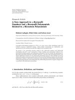
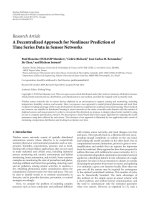
The proposed design flow (Figure 1) uses different mod-
els of computation (MoC), adapted to the particular design
step, to help the designer reasoning about the properties of
the system (like memory hierarchy, parallelism, etc.) while a
Kristof Denolf et al. 3
System specification (C)
Preprocessing & analysis
Golden specification (C)
Memory optimized specification (C)
High-level optimization
Partitioning
Functional model (parallel)
SW tuning HDL translation
SW process
··· ··· HW process
Integration
Executable(s) + netlist
Sequential phaseParallel phase
Figure 1: Different design stages towards a dedicated embedded
core.
programming model (PM) provides the means to describe
it. The flow starts from a system specification (typically pro-
vided by an algorithm group or standardization body like
MPEG) and gradually refines it into the final implementa-
tion: a netlist with an associated set of executables. Two ma-
jor phases are present: (i) a sequential phase aiming to reduce
the complexity with a memory focus and (ii) a parallel phase
in which the application is divided into parallel processes and
mapped to a processor or translated to RTL.
The previously described optimizations [11, 13] of the
sequential phase transform the application into a system with
localized data communication and processing to address the
dominant data cost factor of multimedia. This localized be-
havior is the link to the para llel phase: it allows to extract a
cyclo-static dataflow model to support the partitioning (see
Section 5.1) and it favors small data units p erfectly fitting the
block FIFO of the limited but sufficient set of Communi-
cation Primitives (CPs, Section 5.2) supporting interprocess
data transfers. At the lower level, these CPs can be realized
as zero-copy communication channels to limit their energy
consumption.
The gradual refinement of the system specification as ex-
ecutable behavioral models, described in a well-defined PM,
yields a reference used throughout the design that, combined
with a testbench, enables profound verification in all steps.
Additionally, exploiting the principle of separation of com-
munication and computation in the parallel phase, allows a
structured verification through a combination of simulation
and fast prototyping (Section 6).
3.1. Sequential phase
The optimizations applied in this first design phase are per-
formed on a sequential program (often C code) at the higher
design-level offering the best opportunity for the largest
complexity reduct ions [4, 10, 29]. They have a positive effect
on both terms of the energy delay product and are to a cer-
tain degree independent of the final target platform [11, 13].
The ATOMIUM tool framework [30] is used intensively in
this phase to validate and guide the decisions.
Preprocessing and analysis (see Section 4)
The preprocessing step restricts the reference code to the
required functionality given a particular application profile
and prepares it for a meaningful first complexity analysis that
identifies bottlenecks and initial candidates for optimization.
Its outcome is a golden specification. During this first step,
the testbench triggering all required video tools, resolutions,
framerates, and so forth is fixed. It is used throughout the de-
sign for functional verification and it is automated by scripts.
High-level optimizations (see Section 4)
This design step combines algorithmic tuning with dataflow
transformations at the high-level to produce a memory-
optimized specification. Both optimizations aim at (1) re-
ducing the required amount of processing, (2) introducing
data locality, (3) minimizing the data transfers (especially
to large memories), and (4) limiting the memory footprint.
To also enable data reuse, an appropriate memory hierarchy
is selected. Additionally, the manual rewriting performed in
this step simplifies and cleans the code.
3.2. Parallel phase
The second phase selects a suited partitioning and translates
each resulting process to HDL or optimizes it for a chosen
processor. Introducing parallelism keeps the energy per oper-
ation constant while reducing the delay per operation. Since
the energy per operation is lower for decreased performance
(resulting from voltage-frequency scaling), the parallel solu-
tion will dissipate less power than the original solution [4].
Dedicated hardware can improve both energy and perfor-
mance. Traditional development tools are completed with
the automated RTL environment of Section 6.
Partitioning (see Section 5)
The partitioning derives a suited split of the application in
parallel processes that, together with the memory hierar-
chy, defines the system architecture. The C model is reorga-
nized to closely reflect this selected structure. The buffer sizes
of the interprocess communication channels are calculated
based on the relaxed cyclo-static dataflow [5](Section 5.1)
MoC. The PM is mainly based on a message passing system
and is defined as a limited set of communication primitives
(Section 5.2).
RTL development and software tuning (see Section 6)
The RTL describes the functionality of all tasks in HDL and
tests each module including its communication separately to
verify the correct behavior (Section 6). The software (SW)
tuning adapts the remaining code for the chosen processor(s)
4 EURASIP Journal on Embedded Systems
Table 1: Characteristics of the video sequences in the applied testbench.
Test sequence Frame rates Frame sizes Bitrates (bps)
Mother & daughter 15, 30 QCIF, CIF 75 k, 100 k, 200 k
Foreman 15, 30 QCIF, CIF 200 k, 400 k, 800 k
Calendar & mobile 15, 30 QCIF, CIF 500 k, 1.5 M, 3 M
Harbour 15, 30 QCIF, CIF, 4CIF 100 k, 500 k, 2 M
Crew 15, 30 QCIF, CIF, 4CIF 200 k, 1 M, 4 M, 6 M
City 15, 30 QCIF, CIF, 4CIF 200 k, 1 M, 4 M, 6 M
through processor specific optimizations. The MoC for the
RTL is typically a synchronous or timed one. The PM is the
same as during the partitioning step but is expressed using
an HDL language.
Integration (see Section 6)
The integration phase first combines multiple functional
blocks gradually until the complete system is simulated and
mapped on the target platform.
4. PREPROCESSING AND HIGH-LEVEL
OPTIMIZATIONS
The proposed design flow is further explained while it is
applied on the development of a fully dedicated, scalable
MPEG-4 part 2 Simple Profile video codec. The encoder
and decoder are able to sustain, respectively, up to 4CIF
(704
× 576) at 30 fps and XSGA (1280 × 1024) at 30 fps or
any multistream combination that does not supersede these
throughputs. The similarity of the basic coding scheme of a
MPEG-4 part 2 video codec to that of other ISO MPEG and
ITU-T standards (even more recent ones) makes it a relevant
driver to illustrate the design flow.
After a brief introduction to MPEG-4 video coding, the
testbench and the high-level optimizations are briefly de-
scribed in this section. Only the parallel phase of the encoder
design is discussed in depth in the rest of the paper. Details on
the encoder sequential phase are given in [13]. The decoder
design is described in [31].
The MPEG-4 part 2 video codec [32] belongs to the class
of lossy hybrid video compression algorithms [33]. The ar-
chitecture of Figure 5 also gives a high-level view of the en-
coder. A frame is divided in macroblocks, each containing
6blocksof8
× 8 pixels: 4 luminance and 2 chrominance
blocks. The Motion Estimation (ME) exploits the temporal
redundancy by searching for the best match for each new
input block in the previously reconstructed frame. The mo-
tion vectors define this relative position. The remaining error
information after Motion Compensation (MC) is decorre-
lated spatially using a DCT transform and is then Quantized
(Q). The inverse operations Q
−1
and IDCT (completing the
texture coding chain) and the motion compensation recon-
struct the frame as generated at the decoder side. Finally, the
motion vectors and quantized DCT coefficients are variable
length encoded. Completed with video header information,
they are struc tured in packets in the output buffer. A rate
control algorithm sets the quantization degree to achieve a
specified average bitrate and to avoid over or under flow of
this buffer. The testbench described Ta ble 1 is used at the dif-
ferent design stages. The 6 selected video samples have differ-
ent sizes, framerates and movement complexities. They are
compressed at various bitrates. In total, 20 test sequences are
defined in this testbench.
The software used as system specification is the verifi-
cation model accompanying MPEG-4 part 2 standard [34].
This reference contains all MPEG-4 Video functionality, re-
sulting in oversized C code (around 50 k lines each for an
encoder or a decoder) distributed over many files. Applying
automatic pruning with ATOMIUM extracts only the Simple
Profile video tools and shrinks the code to 30% of its original
size.
Algorithmic tuning
Exploits the freedom available at the encoder side to trade
a limited amount of compression performance (less than
0.5 dB, see [13]) for a large complexity reduction. Two types
of algorithmic optimization are applied: modifications to en-
able macroblock based processing and tuning to reduce the
required processing for each macroblock. The development
of a predictive rate control [35], calculating the mean abso-
lute deviation by only using past information belongs to the
first category. The development of directional squared search
motion estimation [36] and the intelligent block processing
in the texture coding [13] are in the second class.
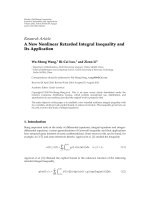
Memor y optimizations
In addition to the algorithmic tuning reducing the ME’s
number of searched positions, a two-level memory hierarchy
(Figure 2) is introduced to limit the number of accesses to the
large frame sized memories. As the ME is intrinsically a lo-
calized process (i.e., the matching criterion computations re-
peatedly access the same set of neighboring pixels), the heav-
ily used data is preloaded from the frame-sized memory to
smaller local buffers. This solution is more efficient as soon
as the cost of the extratransfers is balanced by the advantage
of using smaller memories. The luminance information of
the previous reconstructed frame required by the motion es-
timation/compensation is stored in a bufferY. The search area
buffer is a local copy of the values repetitively accessed dur-
ing the motion estimation. This buffer is circular in the hor-
izontal direction to reduce the amount of writes during the
Kristof Denolf et al. 5
Reconstructed frame
Width
16
Height
2 × width + 3 × 16
3
× 16
3
× 16
BufferY
Search area
Reconstructed current
Current MB
Reconstructed previous
Figure 2: Two-level memory hierarchy enabling data reuse on the
motion estimation and compensation path.
updating of this buffer. Both chrominance components have
a similar bufferU/V to copy the data of the previously recon-
structed frame needed by the motion compensation. In this
way, the newly coded macroblocks can be immediately stored
in the frame memory and a single reconstructed frame is suf-
ficient to support the encoding process. This reconstructed
frame memory has a block-based data organization to en-
able burst oriented reads and writes. Additionally, skipped
blocks wi th zero motion vectors do not need to be stored in
the single reconstructed frame memory, as its content did not
change with respect to the previous frame.
To further increase data locality, the encoding algorithm
is organized to support macroblock-based processing. The
motion compensation, texture coding, and texture update
work on a block granularity. This enables an efficient use
of the communication primitives. The size of the blocks in
the block FIFO queues is minimized (only blocks or mac-
roblocks), off-chip memory accesses are reduced as the re-
constructed frame is maximally read once and written once
per pixel and its accesses are grouped in bursts.
5. PARTITIONING EXPLORATION
The memory-optimized video encoder with localized be-
havior mainly processes data struc tures (e.g., (macro)blocks,
frames) rather than individual data samples as in a typi-
cal DSP system. In such a processing environment the use
of dataflow graphs is a natural choice. The next subsection
briefly introduces Cyclo-Static DataFlow (CSDF) [5], ex-
plains its interpretation and shows how buffer sizes are cal-
culated. Then the set of CPs supporting this CSDF model are
detailed. Finally, the partitioning process of the encoder is
described.
5.1. Partitioning using cyclo-static
dataflow techniques
CSDF is an extension of Static DataFlow (SDF, [14]). These
dataflow MoCs use graphical dataflow to represent the ap-
plication as a directed graph, consisting of actors (processes)
and e dges (communication) between them [37]. Each actor
produces/consumes tokens according to firing r u les, specify-
ing the amount of tokens that need to be available before the
actor can execute (fire). This number of tokens can change
periodically resulting in a c yclo-static behavior.
The data-driven operation of a CSDF graph allows for an
automatic synchronization between the actors: an actor can-
not be executed prior to the arrival of its input tokens. When
agraphcanrunwithoutacontinuousincreaseordecrease
of tokens on its edges (i.e., with finite buffers) it is said to be
consistent and live.
5.1.1. CSDF interpretation
To correctly represent the behavior of the final implemen-
tation, the CSDF model has to be build in a specific way.
First, the limited size and blocking read and blocking write
behavior of the synchronizing communication channels (see
Section 5.2), are expressed in CSDF by adding a backward
edge representing the available buffer space [37]. In this way,
firing an actor consists of 3 steps: (i) acquire: check the avail-
ability of the input tokens and output tokens buffer space,
(ii) execute the code of the function describing the behavior
of the actor (accessing the data in the container of the actor)
and (iii) release: close the production of the output tokens
and the consumption of the input tokens.
Second, as the main focus of the implementation effi-
ciency is on the memory cost, the restrictions on the edges
are relaxed: partial releases are added to the typically ran-
dom accessible data in the container of a token. These par-
tial releases enable releasing only a part of the acquired tokes
to support data re-use. A detailed description of all relaxed
edges is outside the scope of this paper. Section 5.2 realizes
the edges as two groups: synchronizing CPs implementing
the normal CSDF edges and nonsynchronizing CPs for the
relaxed ones.
Finally, the monotonic behavior of a CSDF graph [38]
allows to couple the temporal behavior of the model to the
final implementation. This monotonic execution assures that
smaller Response Times (RTs) of actors can only lead to an
equal or earlier arrival of tokens. Consequently, if the buffer
size calculation of the next section is based on worst-case RTs
and if the implemented actor never exceeds this worst-case
RT, then throughput of the implementation is guaranteed.
5.1.2. Buffer size calculation
Reference [5] shows that a CSDF-graph is fully analyzable at
design time: after calculating the repetition vector q for the
6 EURASIP Journal on Embedded Systems
Block 0 Block 1 ··· Block n − 1
Data 0
Data 1
···
Data k − 1
Data 0
Data 1
···
Data k − 1
Data 0
Data 1
···
Data k − 1
Data 0
Data 1
···
Data k − 1
Full
Op mode
Addr
Data in
Data out
Empty
Op
mode
Addr
Data in
Data out
Op
mode: NOP, read, write, commit
Figure 3: The block FIFO synchronizing communication primitive.
consistency check and determining a single-processor sched-
ule to verify deadlock freedom, a bounded memory analysis
can be performed.
Such buffer length calculation depends on the desired
schedule and the response times of the actors. In line with the
targeted fully dedicated implementation, the desired sched-
ule operates in a fully parallel and pipelined way. It is as-
sumed that every actor runs on its own processor (i.e., no
time multiplexing and sufficient resources) to maximize the
RT of each actor. This inherently eases the job of the designer
handwriting the RTL during the next design step and yields
better synthesis results. Consequently, the RT of each actor A
is inversely proportional to its repetition rate q
A
and can be
expressed relatively to the RT of an ac tor S,
RT
A
=
RT
S
q
S
q
A
. (1)
Under these assumptions and with the CSDF interpre-
tation presented above, the buffer size equals the maximum
amount of the acquired tokens while executing the desired
schedule. Once this buffer sizing is completed, the system has
aself-timedbehavior.
5.2. Communication primitives
The communication primitives support the inter- ac-
tor/process(or) communication and synchronization meth-
ods expressed by the edges in the CSDF model. They form a
library of communication building blocks for the progr am-
ming model that is available at the different abstraction lev-
els of the design process. Only a limited set of strictly defined
CPs are sufficient to support a video codec implementation.
This allows to exploit the principle of separation of commu-
nication and computation [23]intwoways:firsttocreate
and test the CPs separately and second to cut out a functional
module at the borders of its I/O (i.e., the functional compo-
nent and its CPs) and develop and verify it individually (see
Section 6). In this way, functionality in the high-level func-
tional model can be isolated and translated to lower levels,
while the component is completely characterized by the in-
putstimuliandexpectedoutput.
All communication primitives are memory elements that
can hold data containers of the tokens. Practically, depending
on the CP size, registers or embedded RAM implement this
storage. Two main groups of CPs are distinguished: synchro-
nizing and nonsynchronizing CPs. Only the former group
provides synchronization support through its blocking read
and blocking write behavior. Consequently, the proposed de-
sign approach requires that each process of the system has
at least one input synchronizing CP and at least one output
synchronizing CP. The minimal compliance with this con-
dition allows the system to have a self-timed execution that
is controlled by the depth of the synchronizing CPs, sized
according to the desired schedule in the partitioning step
(Section 5.1.2).
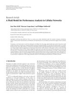
5.2.1. Synchronizing/token-based
communication primitives
The synchronizing CPs signal the presence of a token next
to the storage of the data in the container to support imple-
menting the blocking read and blocking write of the CSDF
MoC (Section 5.1). Two types are available: a scalar FIFO and
a block FIFO (Figure 3).
The most general type, the block FIFO represented in
Figure 3, passes data units (typically a (macro)block) be-
tween processes. It is implemented as a first in first out queue
of data containers. The data in the active container within the
block FIFO can be accessed randomly. The active container
is the block that is currently produced/consumed on the pro-
duction/consumption side. The random access capability of
the active container requires a control signal (op
mode) to
allow the following operations: (1) NOP, (2) read, (3) write,
and (4) commit. The commit command indicates the releas-
ing of the active block (in correspondence to last steps of the
actor firing in the CSDF model of Section 5.1.1).
The block FIFO offers interesting extrafeatures.
(i) Random access in container allowing to produce val-
ues in a different order than they are consumed, like
the (zigzag) scan order for the (I)DCT.
(ii) The active container can be used as scratch pad for lo-
cal temporary data.
(iii) Transfer of variable size data as not all data needs to be
written.
The scalar FIFO is a simplified case of the block FIFO,
where a block contains only a single data element and the
control signal is reduced to either read or write.
5.2.2. Nonsynchronizing communication primitives
The main problem introduced by the token based process-
ing is the impossibility of reusing data between two processes
and the incapability to efficiently handle parameters that are
not aligned on data unit boundaries (e.g., Frame/Slice based
parameters). In order to enable a system to handle these
exceptional cases expressed by relaxed edges in the CSDF
model (Section 5.1.1), the following communication prim-
itives are introduced: shared memory and configuration reg-
isters. As they do not offer token support, they can only
be used between processes that are already connected (indi-
rectly) through synchronizing CPs.
Kristof Denolf et al. 7
Table 2: Detailed information of the actors in the encoder CSDF graph.
Actor name Functionality Repetition rate WCRT (μs)
Input control Load the new video inputs 1 21.0
Copy control Fill the memory hierarchy 1 21.0
Motion estimation Find the motion vectors 1 21.0
Motion compensation Get predicted block and calculate error 6 3.5
Texture coding Transform, quantization and inverse 6 3.5
Texture update Add and clip compensated and predicted blocks 6 3.5
Entropy coding AC/DC, MV prediction and VLC coding 1 21.0
Bitstream packetization Add headers and compose the bitstream
≤ 1 ≥ 21.0
Memory
r/w
Addr
Data in
Data out
r/w
Addr
Data in
Data out
(a) Shared memory
Data in
Valid
Data out
Update
Shadow
Active
(b) Configuration registers
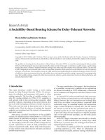
Figure 4: Nonsynchronizing communication primitives.
Shared memory
The shared memory, presented in Figure 4(a), is used to
share pieces of a data array between two or more processes.
It typically holds data that is reused potentially multiple
times (e.g., the search area of a motion estimation engine).
Shared memories are conceptually implemented as multi-
port memories, with the number of ports depending on the
amount of processing units that are simultaneously access-
ing it.
Larger shared memories, with as special case external
memory, are typically implemented with a single port. A
memory controller containing an arbiter handles the accesses
from multiple processing units.
Configuration registers
The configuration registers (Figure 4(b)) are used for unsyn-
chronized communication between functional components
or between hardware and remaining parts in the software.
They typically hold the scalars configuring the application
or the parameters that have a slow variation (e.g., frame pa-
rameters). The configuration registers are implemented as
shadow registers.
5.3. Video pipeline architecture
The constru ction of a n architecture suited for the video en-
coder starts with building a CSDF graph of the high-level
optimized version. The granularity of the actors is chosen
fine enough to enable their efficient implementation as hard-
ware accelerator. Eight actors (see Figure 5)aredefinedfor
the MPEG-4 encoder. Table 2 contains a brief description of
the functionality of each actor and its repetition rate. Adding
the edges to the dataflow graph examines the communica-
tion between them and the required type of CP. The localized
processing of the encoder results in the use of block FIFOs
exchanging (macro)block size data at high transfer rates and
to synchronize all actors. The introduced memory h ierarchy
requires shared memory CPs. At this point of the partition-
ing, all CPs of Figure 5 correspond to an edge and have an
unlimited depth.
By adding a pipelined and parallel operation as desired
schedule, the worst-case response time (WCRT) of each actor
is obtained with (1) for a throughput of 4CIF at 30 fps
(or 47520 macroblocks per second) and listed in Table 2.
These response times are used in the lifetime analysis (of
Section 5.1.2) to calculate the required buffer size of all CPs.
The resulting video pipeline has a self-timed behavior.
The concurrency of its processes is assured by correctly sizing
these communication primitives. In this way, the complete
pipeline behaves like a monolithic hardware accelerator. To
avoid interface overheads [39], the software orchestrator cal-
culates the configuration settings (parameters) for all func-
tional modules on a frame basis. Additionally, the CPs are
realized in hardware as power efficient dedicated zero-copy
communication channels. This avoids first making a local
copy at the producer, then reading it back to send it over a
bus or other communication infrastructure and finally stor-
ing it in another local buffer at the consumer side.
6. RTL DEVELOPMENT AND
VERIFICATION ENVIRONMENT
The proposed RTL development and verification methodol-
ogy simplifies the HW description step of the design flow. It
covers the HDL translation and verification of the individ-
ual functional components and their (partial) composition
into a system. The separation of communication and com-
putation permits the isolated design of a single functional
module. Inserted probes in the C model generate the input
stimuli and the expected output characterizing the behavior
of the block. As the number of stimuli required to completely
test a functional module can be significant, the development
8 EURASIP Journal on Embedded Systems
Table 3: Required operation frequency, off-chip data rates (encoding the City reference video sequence) and FPGA resource consumption
for different levels.
Throughput
(fps) & level
Operation
frequency (MHz)
External
memory (kB)
32-bit external
transfers (10
6
/s)
FPGA resources
Measured Not optimized
2
Measured Not optimized
3
Slices LUTs FFs BRAMs Mults
15 QCIF (L1) 3.2 4.0 37 0.28 0.29 8303 12 630 6093 16 17
15 CIF (L2)
12.9 17.6 149 1.14 1.14 9019 12 778 6335 23 17
30 CIF (L3)
25.6 35.2 149 2.25 2.28 9019 12 778 6335 23 17
30 4CIF (>L5)
100.7 140.6 594 9.07 9.12 9353 13 260 6575 36 17
2
not optimized = proposed ME algorithm (directional squared search) without early stop criteria.
3
not optimized = reading and writing every sample once.
environment supports simulation as well as testing on a pro-
totyping or emulation platform (Figure 6). While the high
signal visibility of simulation norm ally produces long simu-
lation times, the prototyping platform supports much faster
and more extensive testing with the drawback of less signal
observability.
Reinforcing the communication primitives on the soft-
ware model and on the hardware block allows the genera-
tion of the input stimuli and of the expected output from
the software model, together w ith a list of ports g rouped in
the specification file (SPEC). The SPEC2VHDL tool gener-
ates, based on this specification (SPEC) file, the VHDL test-
benches, instantiates the communication primitives required
by the block, and also generates the entity and an empty ar-
chitecture of the designed block. The testbench includes a
VHDL simulation library that links the stimuli/expected out-
put files with the communication primitives. In the simula-
tion library basic control is included to trigger full/empty be-
havior. The communication primitives are instantiated from
a design library, which will also be used for synthesis. At this
point the designer can focus to manually complete only the
architecture of the block.
As the user finishes the design of the block, the exten-
sive testing makes the simulation time a bottleneck. In or-
der to speed up the testing phase, a seamless switch to a fast
prototyping platform based on the same SPEC file and stim-
uli/expected output is supported by SPEC2FPGA. This in-
cludes the generation of the software application, link to the
files, and low-level platform accesses based on a C/C++ li-
brary. Also the platform/FPGA required interfaces are gener-
ated together with the automatic inclusion of the previously
generated entity and implemented architecture.
To minimize the debug and composition effort of the dif-
ferent functional blocks, the verification process uses the tra-
ditional two phases: first blocks are tested separately and then
they are gradually combined to make up the complete sys-
tem. Both phases use the two environments of Figure 6.
The combination of the two above described tools, cre-
ates a powerful design and verification environment. The de-
signer can first debug and correct errors by using the high
signals visibility of the simulation tools. To extensively test
the developed functional module, he uses the speed of the
prototyping platform to identify an error in a potential huge
test bed. As both simulation and hardware verification setups
are functionally identical, the error can be identified on the
prototyping platform with a precision that will allow a rea-
sonable simulation time (e.g., sequence X, f rame Y) in view
of the error correction.
7. IMPLEMENTATION RESULTS
Each actor of Figure 5 is individually translated to HDL using
the development and verification approach described in the
previous section. The partitioning is made in such a way that
the actors are small enough to allow the designer to come up
with a manual RTL implementation that is both energy and
throughput efficient. Setting the target operation frequency
to 100 MHz, results in a budget of 2104 cycles per firing for
the actors with a repetition rate of 1 and a budget of 350 cy-
cles for the actors with a repetition rate of 6 (see Table 2). The
throughput is guaranteed when all actors respect this worst-
case execution time. Because of the temporal monotonic be-
havior (Section 5.1.1) of the self-timed executing pipeline,
shorter execution times can only lead to an equal or higher
performance.
The resulting MPEG-4 part 2 SP encoder is first mapped
on the Xilinx Virtex-II 3000 (XC2V3000-4) FPGA available
on the Wildcard-II [40] used as prototyping/demonstration
platform during verification. Second, the Synopsys tool suite
is combined with Modelsim to evaluate the power efficiency
and size of an ASIC implementation.
7.1. Throughput and Size
Table 3 lists the operation frequencies required to sustain the
throughput of the different MPEG-4 SP levels. The current
design can be clocked up to 100 MHz both on the FPGA
1
and on the ASIC, supporting 30 4CIF frames per second, ex-
ceeding the level 5 requirements of the MPEG standard [41].
Additionally, the encoder core supports processing of multi-
ple video sequences (e.g., 4
× 30 CIF frames per second). The
user can specify the required maximum frame size through
the use of HDL generics to scale the design according to his
needs (Table 3).
1
Frequency achieved for Virtex4 speed grade −10. Implementation on Vir-
tex2 or Spar t an3 may not reach this operating frequency.
Kristof Denolf et al. 9
External
SRAM
Burst 64
Burst 64
Shared memory
Shared memory
Input
controller
Copy
controller
Software
orchestrator
(rate control
& parameters)
Motion
estimation
Motion
compensation
Text ure
coding
Variable
length
coding
Bitstream
packetization
Capture card
Block
FIFO (2)
Block
FIFO (3)
Block
FIFO (2)
Block
FIFO (3)
Block
FIFO (2)
Block
FIFO (2)
Search area
Scalar
FIFO
Motion
vectors
Scalar
FIFO (1)
Scalar
FIFO (1)
Scalar
FIFO (1)
Scalar
FIFO (1)
Scalar
FIFO (1)
Scalar
FIFO (1)
Scalar
FIFO (1)
Output
bitstream
Comp.
block
8
× 8
Error
block
8
× 8
Texture block
8
× 8
Quantized
macroblock
(6
× 8 × 8)
BufferYUV
Current macroblock
(6
× 8 × 8)
New
macro
block
(16
× 16)
Text ure
update
Figure 5: MPEG-4 simple profile encoder block diagram.
SW model
User’s signal
visibility
User’s
regress tests
SPEC
Stimuli
Expected
output
SPEC2VHDL SPEC2FPGA
MT C/C++
TB application
Simulation tools
LIB (VHDL)
VHDL
test bench
CP
instances
HW access
interfaces LIB
(VHDL & PAR)
Block
architecture
Block entity
Communication
primitives LIB
(VHDL)
FPGA CP &
HW interfaces
FPGA platform (WCII)
C++
HW access
API LIB (C++)
Legend
To ol gener a te dUser generated
To ol ’s l ibr aryTo ol ’s c ontex t
Figure 6: Development and verification environment.
10 EURASIP Journal on Embedded Systems
Table 4: Hardware characteristics of the encoder core
Encoder core Power distribution (4CIF 30 fps)
Process UMC 180 nm, 1.62 V part power (mW) share %
Area 3.1
× 3.1 mm2 block FIFO 16.4 23.1
Gate size 88 kGates + 400 kbit SRAM shared memory 13.3 18.7
off-chip memor y 600 Kbyte scalar FIFO 3.8 5.4
Power consumption
3.2 mW QCIF 15 fps (L1) texture coding 20.7 29.2
9.7 mW CIF 15 fps (L2) motion estimation 7.4 10.5
19.2 mW CIF 30 fps (L3) entropy coder 3.4 4.7
71 mW 4CIF 30 fps (>L5) other 6.0 8.4
Table 5: Characteristics of state-of-the-art MPEG-4 part 2 vi deo implementations.
Design
Throughput
(Mpixels/s)
Process
(nm, V)
Frequency
(MHz)
Power
(mW)
Area
(kGates)
On-chip
SRAM
(kbit)
Off-
chip
SDRAM
(Byte)
External
accesses
per pixel
Scaled
Power
(mW)
Scaled
Through-put
(Mpixels/s)
Scaled
energy
per pixel
(nJ/pixel)
Scaled energy
delay product
(nJ
·μs)
[44] 3.0 (L3) 180, — 36 116 170 43 161 k — 116 3.0 38.1 12.5
[45] 1.5 (L2) 180, 1.5 13.5 29 400 — 2 M — 29 1.5 19.1 12.5
[47] 0.4 (L1) 180, 1.5 70 170 — 128 128 k
4
0 170 0.4 447.2 1176.3
[46] 1.5 (L2) 130, 1.5 125 160 3000 — 2 M
4
0 261 1.1 279.3 254.3
[43] 3.0 (L3) 350, 3.3 40 257 207
5
39 2 M >5 14 2.7 5.2 1.9
[42] 27.6 (>L5) 130, 1.3 81 120 390 80 >2.6 M 17 249 23.0 13.3 0.6
[51] 9.2 (L4) 130, 1.2 40.5 50 800 — — — 119 8.3 18.0 2.2
[39] 9.2 (L4) 130, 1 — 9.6 170 — — — 31 10.0 4.1 0.4
[52] 9.2 (L4) 180, 1.4 28.5 18 201 36 — — 21 9.9 2.1 0.2
This
work
12.2 (>L5) 180, 1.6 101 71 87 400 594 k 2 61 11.3 5.4 0.5
4
Moved on-chip using embedded DRAM.
5
Assuming 1 gate = 4transistors.
7.2. Memory requirements
On-chip BRAM (FPGA) or SRAM (ASIC) is used to im-
plement the memory hierarchy and the required amount
scales with the maximum frame size (Table 3). Both the
copy controller (filling the bufferYUV and search area, see
Figure 5) and the texture update make 32 bit burst accesses
(of 64 bytes) to the external memory, holding the recon-
structed frame with a block-based data organization. At 30
4CIF frames per second, this corresponds in worst-case to 9.2
Mtransfers per second (as skipped blocks are not written to
the reconstructed frame, the values of the measured external
transfers in Ta ble 3 are lower). In this way, our implementa-
tion minimizes the off-chip bandwidth with at least a factor
of 2.5 compared to [42–45] without embedding a complete
frame memory as done in [46, 47] (see also Tabl e 5 ). Addi-
tionally, our encoder only requires the storage of one frame
in external memory.
7.3. Power consumption
Power simulations are used to assess the power efficiency of
the proposed implementation. They consist of 3 steps. (1)
Synopsys [48] DC Compiler generates a gate level netlist and
the list of signals to be monitored for power (forward switch-
ing activity file). (2) ModelSim [49] RTL simulation tracks
the actual toggles of the monitored signals and produces the
back-annotated switching activity file. (3) Synopsys Power
Compiler calculates power numbers based on the gate level
netlist from step 1 and back annotated switching ac tivity file
from step 2. Such prelayout gate-level simulations do not
include accurate wire-loads. Internal experiments indicate
their impact limited to a 20% error margin. Additionally, I/O
power is not included.
Table 4 gives the characteristics of the ASIC encoder core
when synthesized for 100 MHz, 4CIF resolution. It also lists
the power consumptions while processing the City reference
video sequence at different levels when clocked at the corre-
sponding operation frequency of Table 3. These numbers do
not include the power of the software orchestrator.
Carefully realizing the communication primitives on the
ASIC allows balancing their power consumption compared
to the logic (Table 4): banking is applied to the large on-chip
bufferYUV and the chip-enable signal of the communication
primitives is precisely controlled to shut down the CP ports
when idle. Finally, clock-gating is applied to the complete en-
coder to further reduce the power consumption. To compare
the energy efficiency to the available state of the art solu-
tions, the power consumption of all implementations (listed
in Ta ble 5) is scaled to the 180 nm, 1.5 V technology node,
Kristof Denolf et al. 11
Reset
Clk
IC
CC
ME
MC
TC
TU
VLC
BP
I frame P frame
2500 μs 2600 μs 2700 μs
Figure 7: Activity diagram of the video pipeline in regime mode. The texture coding ( TC) is the critical path in the I frame, motion
estimation (ME) is the critical path in the P frame.
using (2), where P is the power, V
dd
is the supply voltage and
λ is the feature size. The ITRS roadmap [4, 50] indicates that
beyond 130 nm, the quadratic power scaling (α
= β = 2in
(2)) breaks down and follows a slower trend,
P
2
= P
1
V
dd,2
V
dd,1
α
λ
2
λ
1
β
. (2)
Similarly, the throughput T needs to be scaled as it directly
related to the achievable operation frequency that depends
on the technology node. A linear impact by both the feature
size and the supply voltage is assumed in (3),
T
2
= T
1
V
dd,2
V
dd,1
λ
1
λ
2
. (3)
The scaled energy per pixel in Table 5 compares the avail-
able state of the art MPEG-4 video encoders in a the 180 nm,
1.5 V technology node. The proposed core is clearly more en-
ergy e fficient than [42, 44, 45 , 51]. The power consumption
of [43], including a SW controller, is slightly better (note that
this work does not include the SW orchestrator). However,
taking the off-chip memory accesses into account when eval-
uating the total system power consumption, the proposed
solutions has a (at least) 2.5 times reduced off chip trans-
fer rate, leading to the lowest total power consumption. Even
when compared to the ASICs containing embedded DRAM
[46, 47 ], our implementation is more power-efficient as only
1.5 mW is required at L2 ( 15 CIF fps) to read and write every
pixel from the external memor y (assuming 1.3 nJ per 32 bit
transfer). For L1 and L2 throughput respectively, [46, 47]
consume more than 150 mW (Table 5). Our implementation
delivers 15 CIF fps (L2) consuming only 9.7+1.5
= 11.4mW.
Using complementary techniques, like a low-power CMOS
technology, [39, 52] achieve an even better core energy ef-
ficiency. Insufficient details prevent a complete comparison
including the external memory transfer cost.
The last column of Table 5 presents the scaled energy de-
lay product. This measure includes the scaled throughput as
delay per pixel. The previous observations also hold using
this energy delay product, except for the 30 CIF fps of [43]
having now a worse result than the proposed encoder. Note
that a complete comparison should also include the coding
efficiency of the different solutions as algori thmic optimiza-
tions (like different ME algorithms) sacrifice compression
performance to reduce complexity. Unfortunately, not all re-
ferred papers contain the required rate-distortion informa-
tion to make such evaluation.
7.4. Effect of the high-level optimizations
The algorithmic optimizations of Section 4 reduce the aver-
age number of cycles to process a macroblock compared to
the worst-case (typically around 25%, see Table 3) and hence
lower the power consumption.
Figure 7 shows the activity diagram of the pipelined en-
coder in regime mode. The signal names are the acronyms
of the different functional modules in Figure 5. During the
I frame (left side of the dotted line in Figure 7), the texture
coding (“TC”) is the critical path as it always processes the
complete error block.
During a P frame (right side of the dotted line in
Figure 7), the search for a good match in the previous frame
is the critical path (“ME”). The early stop criteria sometimes
shorten the amount of cycles required during the motion es-
timation. When this occurs, often a good match is found, al-
lowing the texture coding to apply its intelligent block pro-
cessing that reduces the amount of cycles spend to process the
macroblock. In this way both critical paths are balanced (i.e.,
without algorithmic tuning of the texture coding, this pro-
cess would become the new critical path in a P frame). Ad-
ditionally, a good match leads to a higher amount of skipped
blocks with possible zero motion vectors. Consequently, the
algorithmic tuning reduces the amount of processing and
data communication, leading to improved power efficiency.
12 EURASIP Journal on Embedded Systems
8. CONCLUSIONS
Modern multimedia applications seek to improve the user
experience by invoking advanced techniques and by increas-
ing resolutions. To meet the power and heat dissipation lim-
itations of portable devices, their implementation requires
a set of various power optimization techniques at different
design levels: (i) redefine the problem to reduce complexity,
(ii) introduce parallelism to reduce energy per operation and
(ii) add specialized hardware as it achieves the best energy
efficiency. This philosophy is reflected in the proposed de-
sign flow bridging the gap between a high-level specification
(typically C) into the final implementation at RTL level. The
typical data dominance of multimedia systems motivates the
memory and communication focus of the design flow.
In the first phase of the design flow, the reference code
is transformed through memory and algorithmic optimiza-
tions into a block-based video application with localized pro-
cessing and data flow. Memory footprint and frame memory
accesses are minimized. These optimizations prepare the sys-
tem for introducing parallelism and provide a reference for
the RTL development.
The second design phase starts with partitioning the ap-
plication in a set of concurrent processes to achieve the
required throughput and to improve the energy efficiency.
Based on a CSDF model of computation, used in a specific
way to also express implementation specific aspects, the re-
quired buffers sizes of the graph edges are calculated to ob-
tain a fully pipelined and parallel self-timed execution. By
exploiting the principle of separation of communication and
computation, each actor is tr a nslated individually to HDL
while correctly modeling its communication. An automated
environment supports the functional verification of such
component by combining simulation of the RTL model and
testing the RTL implementation on a prototyping platform.
The elaborate verification of each single component reduces
the debug cycle for integration.
The design methodology is demonstrated on the devel-
opment of a MPEG-4 Simple Profile video encoder capable
of processing 30 4CIF (704
× 576) frames per second or mul-
tiple lower resolution sequences. Starting from the reference
code, a dedicated video pipeline is realized on an FPGA and
ASIC. The core achieves a high degree of concurrency, uses a
dedicated memory hierarchy and exploits burst oriented ex-
ternal memory I/O leading to the theoretical minimum of
off-chip accesses. The video codec design is scalable with a
number of added compile-time parameters (e.g., maximum
frame size and number of bitstreams) which can be set by
the user to best suit his application. The presented encoder
core uses 71 mW (180 nm, 1.62 V UMC technology) when
processing 4CIF at 30 fps.
REFERENCES
[1] M. A. Viredaz and D. A. Wallach, “Power evaluation of a hand-
held computer,” IEEE Micro, vol. 23, no. 1, pp. 66–74, 2003.
[2] A. Lambrechts, P. Raghavan, A. Leroy, et al., “Power break-
down analysis for a heterogeneous NoC platform running a
video application,” in Proceedings of the 16th IEEE Interna-
tional Conference on Application-Specific Systems, Architectures
and Processors (ASAP ’05), pp. 179–184, Samos, Greece, July
2005.
[3] T. Fujiyoshi, S. Shiratake, S. Nomura, et al., “A 63-mW
H.264/MPEG-4 audio/visual codec LSI with module-wise dy-
namic voltage/frequency scaling,” IEEE Journal of Solid-State
Circuits, vol. 41, no. 1, pp. 54–62, 2006.
[4] M. Horowitz, E. Alon, D. Patil, S. Naffziger, R. Kumar, and
K. Bernstein, “Scaling, power, and the future of CMOS,” in
Proceedings of IEEE Internat ional Electron Devices Meeting
(IEDM ’05), p. 7, Washington, DC, USA, December 2005.
[5] G. Bilsen, M. Engels, R. Lauwereins, and J. Peperstraete,
“Cyclo-static dataflow,” IEEE Transactions on Signal Processing,
vol. 44, no. 2, pp. 397–408, 1996.
[6] P. Pirsch, M. Berekovic, H J. Stolberg, and J. Jachalsky, “VLSI
architectures for MPEG-4,” in Proceedings of International
Symposium on VLSI Technology, Syste ms, and Applications
(VTSA ’03), pp. 208A–208E, Hsinchu, Taiwan, October 2003.
[7] S Y. Chien, Y W. Huang, C Y. Chen, H. H. Chen, and L G.
Chen, “Hardware architecture design of video compression for
multimedia communication systems,” IEEE Communications
Magazine, vol. 43, no. 8, pp. 123–131, 2005.
[8] C J. Lian, Y W. Huang, H C. Fang, Y C. Chang, and L
G. Chen, “JPEG, MPEG-4, and H.264 codec IP develop-
ment,” in Proceedings of Design, Automation and Test in Europe
(DATE ’05), vol. 2, pp. 1118–1119, Munich, Germany, March
2005.
[9] S. Edwards, L. Lavagno, E. A. Lee, and A. Sangiovanni-
Vincentelli, “Design of embedded systems: formal models, val-
idation, and synthesis,” Proceedings of the IEEE, vol. 85, no. 3,
pp. 366–390, 1997.
[10] L. Mazzoni, “Power aware design for embedded systems,” IEE
Electronics Systems and Software, vol. 1, no. 5, pp. 12–17, 2003.
[11] F. Catthoor, S. Wuytack, E. de Greef, F. Balasa, L. Nachtergaele,
and A. Vandecappelle, Custom Memory Management Method-
ology: Exploration of Memory Organization for Embedded Mul-
timedia System Design, Kluwer Academic Publishers, Norwell,
Mass, USA, 1998.
[12] P.R.Panda,F.Catthoor,N.D.Dutt,etal.,“Dataandmem-
ory optimization techniques for embedded systems,” ACM
Transactions on Design Automation of Electronic Systems, vol. 6,
no. 2, pp. 149–206, 2001.
[13] K. Denolf, C. de Vleeschouwer, R. Turney, G. Lafruit, and J.
Bormans, “Memory centric design of an MPEG-4 video en-
coder,” IEEE Transactions on Circuits and Systems for Video
Technology, vol. 15, no. 5, pp. 609–619, 2005.
[14] E. A. Lee and T. M. Parks, “Dataflow process networks,” Pro-
ceedings of the IEEE, vol. 83, no. 5, pp. 773–801, 1995.
[15] A. Davare, Q. Zhu, J. Moondanos, and A. Sangiovanni-
Vincentelli, “JPEG encoding on the Intel MXP5800: a
platform-based design case study,” in Proceedings of the 3rd
IEEE Workshop on Embedded Systems for Real-Time Multime-
dia (ESTImedia ’05), pp. 89–94, New York, NY, USA, Septem-
ber 2005.
[16] H. Hwang, T. Oh, H. Jung, and S. Ha, “Conversion of reference
C code to dataflow model: H.264 encoder case study,” in Pro-
ceedings of the Asia and South Pacific D esign Automation Con-
ference (ASP-DAC ’06), pp. 152–157, Yokohama, Japan, Jan-
uary 2006.
[17] F.Haim,M.Sen,D I.Ko,S.S.Bhattacharyya,andW.Wolf,
“Mapping multimedia applications onto configurable hard-
ware with parameterized cyclo-static dataflow graphs,” in Pro-
ceedings of IEEE International Conference on Acoustics, Speech,
Kristof Denolf et al. 13
and Signal Processing (ICASSP ’06), vol. 3, pp. 1052–1055,
Toulouse, France, May 2006.
[18] M. C. Williamson and E. A. Lee, “Synthesis of parallel
hardware implementations from synchronous dataflow graph
specifications,” in Proceedings of the 30th Asilomar Conference
on Signals, Systems and Computers, vol. 2, pp. 1340–1343, Pa-
cific Grove, Calif, USA, November 1996.
[19] J. Horstmannshoff and H. Meyr, “Efficient building block
based RTL code generation from synchronous data flow
graphs,” in Proceedings of the 37th Conference on Design Au-
tomation (DAC ’00), pp. 552–555, Los Angeles, Calif, USA,
June 2000.
[20] H.Jung,K.Lee,andS.Ha,“Efficient hardware controller syn-
thesis for synchronous dataflow graph in system level design,”
IEEE Transactions on Very Large Scale Integration (VLSI) Sys-
tems, vol. 10, no. 4, pp. 423–428, 2002.
[21] J. Dalcolmo, R. Lauwereins, and M. Ade, “Code generation of
data dominated DSP applications for FPGA targets,” in Pro-
ceedings of the 9th IEEE International Workshop on Rapid Sys-
tem Prototyping, pp. 162–167, Leuven, Belgium, June 1998.
[22] R. Grou-Szabo, H. Ghattas, Y. Savaria, and G. Nicolescu,
“Component-based methodology for hardware design of a
dataflow processing network,” in Proceedings of the 5th Inter-
national Workshop on System-on-Chip for Real-Time Applica-
tions (IWSOC ’05), pp. 289–294, Banff, Alberta, Canada, July
2005.
[23] K. Keutzer, A. R. Newton, J. M. Rabaey, and A. Sangiovanni-
Vincentelli, “System-level design: orthogonalization of con-
cerns and platform-based design,” IEEE Transactions on
Computer-Aided Design of Integrated Circuits and Systems,
vol. 19, no. 12, pp. 1523–1543, 2000.
[24] D. Denning, N. Harold, M. Devlin, and J. Irvine, “Using sys-
tem generator to design a reconfigurable video encr yption sys-
tem,” in Proceedings of the 13th International Conference on
Field Programmable Logic and Applications (FPL ’03), pp. 980–
983, Lisbon, Portugal, September 2003.
[25] Y. Nakamura, K. Hosokawa, I. Kuroda, K. Yoshikawa, and T.
Yoshimura, “A fast hardware/software co-verification method
for system-on-a-chip by using a C/C++ simulator and FPGA
emulator with shared register communication,” in Proceedings
of the 41st Design Automation Conference (DAC ’04), pp. 299–
304, San Diego, Calif, USA, June 2004.
[26] R. Siripokarpirom and F. Mayer-Lindenberg, “Hardware-
assisted simulation and evaluation of IP cores using FPGA-
based rapid prototyping boards,” in Proceedings of the 15th
IEEE International Workshop on Rapid Systems Prototyping,pp.
96–102, Geneva, Switzerland, June 2004.
[27]I.Amer,M.Sayed,W.Badawy,andG.Jullien,“Ontheway
to an H.264 HW/SW reference model: a systemC modeling
strategy to integrate selected IP-blocks with the H.264 software
reference model,” in Proceedings of IEEE Workshop on Signal
Processing Systems Design and Implementation (SIPS ’05),pp.
178–181, Athens, Greece, November 2005.
[28] I. Amer, C. A. Rahman, T. Mohamed, M. Sayed, and W.
Badawy, “A hardware-accelerated framework with IP-blocks
for application in MPEG-4,” in Proceedings of t he 5th Interna-
tional Workshop on System-on-Chip for Real-Time Applications
(IWSOC ’05), pp. 211–214, Banff, Alberta, Canada, July 2005.
[29] M. J. Irwin, M. T. Kandemir, N. Vijaykrishnan, and A. Siva-
subramaniam, “A holistic approach to system level energy op-
timization,” in Proceedings of the 10th International Workshop
on Integrated Circuit Design, Power and Timing Modeling, Opti-
mization and Simulation (PATMOS ’00), pp. 88–107, Springer,
G
¨
ottingen, Germany, September 2000.
[30] />[31] P. Schumacher, K. Denolf, A. Chirila-Rus, et al., “A scalable,
multi-stream MPEG-4 video decoder for conferencing and
surveillance applications,” in Proceedings of IEEE International
Conference on Image Processing (ICIP ’05), vol. 2, pp. 886–889,
Genova, Italy, September 2005.
[32] “Information technology—generic coding of audio-visual
objects—part 2: visual,” ISO/IEC 14496-2:2004, June 2004.
[33] V. Bhaskaran and K. Konstantinides, Image and Video Com-
pression Standards, Algorithms and Architectures,KluwerAca-
demic Publishers, Boston, Mass, USA, 1997.
[34] “Information technology—generic coding of audio-visual
objects—part 5: reference software,” ISO/IEC 14496-5:2001,
December 2001.
[35] C. de Vleeschouwer, “Model-based rate control implemen-
tation for low-power video communications systems,” IEEE
Transactions on Circuits and Systems for Video Technology,
vol. 13, no. 12, pp. 1187–1194, 2003.
[36] C. de Vleeschouwer, T. Nilsson, K. Denolf, and J. Bor-
mans, “Algorithmic and architectural co-design of a motion-
estimation engine for low-power video devices,” IEEE Trans-
actions on Circuits and Systems for Video Technology, vol. 12,
no. 12, pp. 1093–1105, 2002.
[37] S. Sriram and S. S. Bhattacharyya, Embedded Multiprocessors:
Scheduling and Synchronization , Marcel Dekker, New York,
NY, USA, 2000.
[38] M. Wiggers, M. Bekooij, P. Jansen, and G. Smit, “Efficient
computationofbuffer capacities for multi-rate real-time sys-
tems with back-pressure,” in Proceedings of the 4th Interna-
tional Conference on Hardware/Software Codesign and System
Synthesis (CODES+ISSS ’06), pp. 10–15, Seoul, Korea, Octo-
ber 2006.
[39] T. Rintaluoma, O. Silven, and J. R aekallio, “Interface overheads
in embedded multimedia software,” in Proceedings of the 6th
International Workshop on Embedded Computer Systems: Ar-
chitectures, Modeling, and Simulation (SAMOS ’06), pp. 5–14,
Samos, Greece, July 2006.
[40] />[41] ISO/IEC JTC1/SC29WG11, “Information technology—
generic coding of audio-visual objects—part 2: visual, amend-
ment 2: new levels for simple profile,” Tech. Rep. N6496,
Redmond, USA, 2004.
[42] H. Yamauchi, S. Okada, T. Watanabe, et al., “An 81MHz, 1280
× 720pixels × 30frames/s MPEG-4 video/audio codec proces-
sor,” in Proceedings of IEEE Internat ional Solid-State Circuits
Conference (ISSCC ’05), vol. 1, pp. 130–589, San Francisco,
Calif, USA, February 2005.
[43] Y C. Chang, W M. Chao, and L G. Chen, “Platform-based
MPEG-4 video encoder SOC design,” in Proceedings of IEEE
Workshop on Signal Processing Systems Design and Implementa-
tion (SIPS ’04), pp. 251–256, Austin, Tex, USA, October 2004.
[44] Amphion, “Standalone MPEG-4 video encoders,” 2003,
CS6701 product specification.
[45] H. Nakayama, T. Yoshitake, H. Komazaki, et al., “An MPEG-
4 video LSI with an error-resilient codec core based on a fast
motion estimation algorithm,” in Proceedings of IEEE Interna-
tional Solid-State Circuits Conference (ISSCC ’02), vol. 1, pp.
368–474, San Francisco, Calif, USA, February 2002.
[46] H. Arakida, M. Takahashi, Y. Tsuboi, et al., “A 160 mW, 80
nA standby, MPEG-4 audiovisual LSI with 16 Mb embedded
14 EURASIP Journal on Embedded Systems
DRAM and a 5 GOPS adaptive post filter,” in Proceedings of
IEEE International Solid-State Circuits Conference (ISSCC ’03),
vol. 1, pp. 42–476, San Francisco, Calif, USA, February 2003.
[47] T. Yamada, N. Irie, J. Nishimoto, et al., “A 133 MHz 170 mW
10 μA standby application processor for 3G cellular phones,”
in Proceedings of IEEE International Solid-State Circuits Con-
ference (ISSCC ’02), vol. 1, pp. 370–474, San Francisco, Calif,
USA, February 2002.
[48] />[49] />[50] />Design 2006Update.pdf.
[51] Y. Watanabe, T. Yoshitake, K. Morioka, et al., “Low power
MPEG-4 ASP codec IP macro for high quality mobile video
applications,” in Proceedings of IEEE International Conference
on Consumer Electronics (ICCE ’05), pp. 337–338, Las Vegas,
Nev, USA, January 2005.
[52] C P. Lin, P C. Tseng, Y T. Chiu, et al., “A 5mW M PEG4
SP encoder w ith 2D bandwidth-sharing motion estimation
for mobile applications,” in Proceedings of IEEE International
Solid-State Circuits Conference (ISSCC ’06), vol. 1, pp. 1626–
1635, San Francisco, Calif, USA, February 2006.