Báo cáo hóa học: " Research Article Implementing a WLAN Video Terminal Using UML and Fully Automated Design Flow" ppt
Bạn đang xem bản rút gọn của tài liệu. Xem và tải ngay bản đầy đủ của tài liệu tại đây (2.11 MB, 15 trang )
Hindawi Publishing Corporation
EURASIP Journal on Embedded Systems
Volume 2007, Article ID 85029, 15 pages
doi:10.1155/2007/85029
Research Article
Implementing a WLAN Video Terminal Using UML and
Fully Automated Design Flow
Petri Kukkala,
1
Mikko Set
¨
al
¨
a,
2
Tero Arpinen,
2
Erno Salminen,
2
Marko H
¨
annik
¨
ainen,
2
and Timo D. H
¨
am
¨
al
¨
ainen
2
1
Nokia Technology Platforms, Visiokatu 6, 33720 Tampere, Finland
2
Institute of Digital and Computer Systems, Tampere University of Technology, Korkeakoulunkatu 1, 33720 Tampere, Finland
Received 28 July 2006; Revised 12 December 2006; Accepted 10 January 2007
Recommended by Gang Qu
This case study presents UML-based design and implementation of a wireless video terminal on a multiprocessor system-on-
chip (SoC). The terminal comprises video encoder and WLAN communications subsystems. In this paper, we present the UML
models used in designing the functionality of the subsystems as well as the architecture of the terminal hardware. We use the Koski
design flow and tools for fully automated implementation of the terminal on FPGA. Measurements were performed to evaluate the
performance of the FPGA implementation. Currently, fully software encoder achieves the frame rate of 3.0 fps with three 50 MHz
processors, which is one half of a reference C implementation. Thus, using UML and design automation reduces the performance,
but we argue that this is highly accepted as we gain significant improvement in design efficiency and flexibility. The experiments
with the UML-based design flow proved its suitability and competence in designing complex embedded multimedia terminals.
Copyright © 2007 Petri Kukkala et al. This is an open access article distributed under the Creative Commons Attribution License,
which permits unrestricted use, distribution, and reproduction in any medium, provided the original work is properly cited.
1. INTRODUCTION
Modern embedded systems have an increasing complexity
as they introduce various multimedia and communication
functionalities. Novel design methods enable efficient system
design with rapid path to prototyping for feasibility analysis
and performance evaluation, and final implementation.
High-abstraction level design languages have been intro-
duced as a solution for the problem. Unified modeling lan-
guage (UML) is converging to a general design language that
can be understood by system designers as well as softare and
hardware engineers [1]. UML is encouraging the develop-
ment of model-based design methodologies, such as model
driven architecture (MDA) [2, 3] that aims at “portability,
interoperability, and reusability through architectural sepa-
ration of concerns” as stated in [4].
Refining the high-abstraction level models towards a
physical implementation requires design automation tools
due to the vast design space. This means high investments
and research effort in tool development to fully exploit new
modeling methodologies. High degree of design automa-
tion also requires flexible hardware and software platforms
to support automated synthesis and configuration. Hence,
versatile hardware/software libraries and run-time environ-
ments are needed.
Configurability usually complicates the library develop-
ment and induces various overheads (execution time, mem-
ory usage) compared to manually optimized application-
specific solutions. However, we argue that automation is
needed to handle the complexity and to allow fast time-to-
market, and we have to pay the price. Naturally, the trade-off
between high performance and fast development time must
be defined case by case.
To meet these desig n challenges in prac tice, we have
to define a practical design methodology for the domain of
embedded real-time systems. To exploit the design method-
ology, we have to map the concepts of the methodology
to the constructs of a high-abstraction level language. Fur-
ther, we have to develop design tools and platforms (or
adapt existing ones) that support the methodology and lan-
guage.
In this paper, we present an extensive case study for the
implementation of a wireless video terminal using a UML 2.0-
based design methodology and fully automated design flow.
The paper introduces UML modeling, tools, and platforms to
implement a whole complex embedded terminal with several
2 EURASIP Journal on Embedded Systems
subsystems. This is a novel approach to exploit UML in the
implementation of such a complex design.
The implemented terminal comprises video encoder and
wireless local area network (WLAN) communications sub-
ystems, which are modeled in UML. Also, the hardware ar-
chitecture and the distributed execution of application are
modeled in UML. Using these models and Koski design flow
[5] the terminal is implemented as a multiprocessor system-
on-chip (SoC) on a single FPGA.
The paper is organized as follows. Section 2 presents the
related work. The Koski design flow is presented in Section 3.
Section 4 presents the utilized hardware and software plat-
forms. The wireless video terminal and related UML models
are presented in Section 5. The implementation details and
performance measurements are presented in Section 6.Fi-
nally, Section 7 concludes the paper.
2. RELATED WORK
Since object management group (OMG) adopted the UML
standard in 1997, it has been widely used in the software in-
dustry. Currently, the latest adopted release is known as UML
2.0 [6]. A number of extension proposals (called proiles)have
been presented for the domain of real-time and embedded
systems design.
The implementation of the wireless video terminal is car-
ried out using the UML-based Koski design flow [5]. UML is
used to design both the functionality of the subsystems and
the underlying hardware architecture. UML 2.0 was chosen
as a design language based on three main reasons. First, pre-
vious experiences have shown that UML suits well the imple-
mentation of communication protocols and wireless termi-
nals [7, 8]. Second, UML 2.0 and design tools provide formal
action semantics and code generation, which enable rapid
prototyping. Third, UML is an object-oriented language, and
supports modular design approach that is an important as-
pect of reusable and flexible design.
This section presents briefly the main related work con-
sidering UML modeling in embedded systems design, and
the parallel, and distributed execution of applications.
2.1. UML modeling with emb edded systems
The UML profiles for the domain of real-time and embed-
ded systems design can be roughly divided into three cate-
gories: system and platform design, performance modeling,
and behavioral design. Next, the main related proposals are
presented.
The embedded UML [9] is a UML profile proposal suit-
able for embedded real-time system specification, design,
and verification. It represents a synthesis of concepts in
hardare/software codesign. It presents extensions that define
functional encapsulation and composition, communication
specification, and mapping for perform ance evaluation.
A UML platform profile is proposed in [10], which
presents a graphical language for the specification. It in-
cludes domain-specific classifiers and relationships to model
the structure and behavior of embedded systems. The profile
introduces new building blocks to represent platform re-
sources and services, and presents proper UML diagrams and
notations to model platforms in different abstraction levels.
The UML profile for schedulability, performance, and time
(or UML-SPT) is standardized by OMG [11]. The profile
defines notations for building models of real-time systems
with relevant quality of service (QoS) parameters. The pro-
file supports the interoperability of modeling and analysis
tools. However, it does not specify a full methodology, and
the proile is considered to be very complex to utilize.
The UML-RT profile [12] defines execution semantics to
capture behavior for simulation and synthesis. The profile
presents capsules to represent system components, the inter-
nal behavior of which is designed with state machines. The
capabilities to model architecture and performance are very
limited in UML-RT, and thus, it should be considered com-
plementary to the real-time UML profile. HASoC [13]isa
design methodology that is based on UML-RT. It proposes
also additional models of computation for the design of in-
ternal behavior.
In [14], Pllana and Fahringer present a set of building
blocks to model concepts of message passing and shared
memory. The proposed building blocks are parameterized to
exploit time constructs in modeling. Further, they present an
approach to map activity diagrams to process topologies.
OMG has recently introduced specifications for SoC
and systems design domains. The UML profile for SoC [15]
presents syntax for modeling modules and channels, the fun-
damental elements of SoC design. Further, the profile enables
describing the behavior of a SoC using protocols and syn-
chronicity semantics. The OMG systems modeling language
(SysML) [16
], and related UML profile for systems engineer-
ing, presents a new general-purpose modeling language for
systems engineering. SysML uses a subset of UML, and its
objective is to improve analysis capabilities.
These proposed UML profiles contain several features for
utilizing UML in embedded and real-time domains. How-
ever, they are particularly targeted to single distinct aspects of
design, and they miss the completeness for combining appli-
cation and platform in an implementation-oriented fashion.
It seems that many research activities have spent years and
years for specifying astonishingly complex profiles that h ave
only minor (reported) practical use.
2.2. Parallelism and distributed execution
Studies in microprocessor design have shown that a multi-
processor architecture consisting of several simple CPUs can
outperform a single CPU using the same area [17] if the ap-
plication has a large degree of parallelism. For the communi-
cations subsystem, Kaiserswerth has analyzed parallelism in
communication protocols [18], stating that they are suitable
for distributed execution, since they can be parallelized effi-
ciently and also allow for pipelined execution.
Several parallel solutions have been developed to reduce
the high computational complexity of video encoding [19].
Temporal parallelism [20, 21] exploits the independency be-
tween subsequent video frames. Consequently, the frame
Petri Kukkala et al. 3
prediction is problematic because it limits the available paral-
lelism. Furthermore, the induced latency may be intolerable
in real-time systems. For functional parallelism [22–24], dif-
ferent functions are pipelined and executed in parallel on dif-
ferent processing units. This method is very straightforward
and can efficiently exploit application-specific hardware ac-
celerators. However, it may have limited scalability. In data
parallelism [25, 26] video frames are divided into uniform
spatial regions that are encoded in parallel. A typical ap-
proach is to use horizontal slice structures for this.
A common approach for simplifying the design of dis-
tributed systems i s to utilize middleware,suchasthecommon
object request broker architecture (CORBA) [27], to abstract
the underlying hardware for the application. OMG has also
specified a UML profile for CORBA, which allows the presen-
tation of CORBA semantics in UML [28]. However, the gen-
eral middleware implementations are too complex for em-
bedded systems. Thus, several lighter middleware approaches
have been developed especial ly for real-time embedded sys-
tems [29–31 ]. However, Rintaluoma et al. [32] state that the
overhead caused by the software layering and middleware
have significant influence on performance in embedded mul-
timedia applications.
In [33], Born et al. have presented a method for the
design and development of distributed applications using
UML. It uses automatic code generation to create code skele-
tons for component implementations on a middleware plat-
form. Still, direct executable code generation from UML
models, or modeling of hardware in UML, is not utilized.
2.3. Our approach
In this work, we use TUT-profile [34] that is a UML profile
especially targeted to improve design efficiency and flexibil-
ity in the implementation and rapid prototyping of embed-
ded real-time systems. The profile introduces a set of UML
stereotypes which categorize and parameterize model con-
structs to enable extensive design automation both in analy-
sis and implementation.
This work uses TUT-profile and the related design
methodology in the design of parallel applications. The
developed platforms and run-time environment seamlessly
support functional parallelism and distributed execution of
applications modeled in UML. The cost we have to pay for
this is the overhead in execution time and increased memory
usage. We argue that these drawbacks are highly accepted as
we gain significant improvement in design efficiency.
The improved design efficiency comes from the clear
modeling constructs and reduced amount of “low-level”
coding, high-degree of design automation, easy model mod-
ifications and rapid prototyping, and improved design man-
agement and reuse. Unfortunately, these benefits in design
efficiency are extremely hard to quantify, in contrast to the
measurable overheads, but we will discuss our experiences in
the design process.
None of the listed works provide fully automated de-
sign tools and practical, complex case studies on the deploy-
ment of the methods. To our best knowledge, the case study
presented in this paper is the most complex design case that
utilizes UML-based design automation for automated paral-
lelization and distribution in this scale.
3. UML MODELING WITH KOSKI
In Koski, the w hole design flow is governed by UML models
designed according to a well-defined UML profile for em-
bedded system design, called TUT-profile [34, 35]. The pro-
file introduces a set of UML stereotypes which categorize and
parameterize model elements to improve design automation
both in analysis and implementation. The TUT-profile di-
vides UML modeling into the design of application, architec-
ture, and mapping models.
The application model is independent of hardware ar-
chitecture and defines both the functionality and structure
of an application. In a complex terminal with several sub-
systems, each subsystem can be described in a separate ap-
plication model. In the TUT-profile, application process is
an elementary unit of execution, which is implemented as
an asynchronously communicating extended finite state ma-
chine (EFSM) using UML statecharts with action semantics
[36, 37]. Further, existing library functions, for example DSP
functions written in C, can be c alled inside the statecharts to
enable efficient reuse.
The architecture model is independent of the applica-
tion, and instantiates the required set of hardware compo-
nents according to the needs of the current design. Hardware
components are selected from a platform library that con-
tains available processing elements as well as on-chip com-
munication networks and interfaces for external (off-chip)
devices. Processing elements are either general-purpose pro-
cessors or dedicated hardware accelerators. The UML models
of the components are abstract parameterized models, and
do not describe the functionality.
The mapping model defines the mapping of an applica-
tion to an architecture, that is, how application processes are
executed on the instantiated processing elements. The map-
ping is performed in two stages. First, application processes
are grouped into process groups. Second, the process groups
are mapped to an architecture. Grouping can be performed
according to different criteria, such as workload distribu-
tion and communication activity between groups. It should
be noted that the mapping model is not compulsory. Koski
tools perform the mapping automatically, but the designer
can also control the mapping manually using the mapping
model.
TUT-profile is further discussed below, in the implemen-
tation of the wireless video terminal.
3.1. Design flow and tools
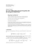
Koski enables a f ully automated implementation for a mul-
tiprocessor SoC on FPGA according to the UML models.
A simplified view is presented in Figure 1. Koski comprises
commercial design tools and self-made tools [38, 39]aspre-
sented in Ta ble 1. A detailed description of the flow is g iven
in [5].
4 EURASIP Journal on Embedded Systems
Modeling in UML with TUT-profile
UML models
Application model Mapping model Architecture model
UML models
Function
library
Run-time
library
Code generation
Architecture
configuration
Hardware
synthesis
Platform
library
Ccodes
Software build
RTL models
Wireless video terminal
on multiprocessor SoC on FPGA
Figure 1: UML-based design flow for the implementation of the wireless video terminal.
Table 1: Categorization of the components and tools used in Koski.
Category Self-made components/tools Off-the-shelf components/tools
Application
TUTMAC UML model
VideoencoderUMLmodel
Design methodology and tools
TUT-profile Tau G2 UML 2.0 tool
Application distribution tool Quartus II 5.1
Architecture configuration tool Nios II GCC toolset
Koski GUI
Execution monitor
Software platform
IPC support functions eCos RTOS
HIBI API State machine scheduler
Hardware accelerator device drivers
Hardware platform
HIBI communication architecture Nios II softcore CPU
Nios-HIBI DMA FPGA development board
Hardware accelerators Intersil WLAN radio transceiver
Extension card for WLAN radio OmniVision on-board camera module
Extension card for on-board camera
Based on the application and mapping models, Koski
generates code from UML statecharts, includes library func-
tions and a run-time library, and finally builds distributed
software implementing desired applications a nd subsystems
on a given architecture. Based on the architecture model,
Koski configures the library-based platform using the archi-
tecture configuration tool [38], and synthesizes the hardware
for a multiprocessor SoC on FPGA.
4. EXECUTION PLATFORM
This section presents the execution platform including both
the multiprocessor SoC platform and the software platform
for the application distribution.
4.1. Hardware platform
The wireless video terminal is implemented on an Altera
FPGA development board. The development board com-
prises Altera Stratix II EP2S60 FPGA, external memories
(1 MB SRAM, 32 MB SDR SDRAM, 16 MB flash), and exter-
nal interfaces (Ethernet and RS-232). Further, we have added
extension cards for a WLAN radio and on-board camera on
the development board. The WLAN radio is Intersil MAC-
less 2.4 GHz WLAN radio transceiver, which is compatible
with the 802.11b physical layer, but does not implement the
medium access control (MAC) layer. The on-board camera
is OmniVision OV7670FSL camera and lens module, wh ich
features a single-chip VGA camera and image processor. The
camera has a maximum frame rate of 30 fps in VGA and sup-
ports image sizes from VGA resolution down to 40
× 30 pix-
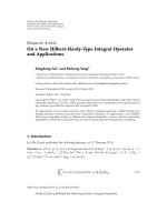
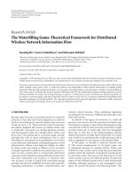
els. A photo of the board with the radio and camera cards is
presented in Figure 2. The development board is connected
to PC via Ethernet (for transferring data) and serial cable (for
debug, diagnostics, and configuration).
The multiprocessor SoC platform is implemented on
FPGA. The platform contains up to five Nios II processors;
four processors for application execution, and one for debug-
ging purposes and interfacing Ethernet with TCP/IP stack.
With a larger FPGA device, such as Stratix II EP2S180, up
to 15 processors can be u sed. Further, the platform con-
tains dedicated hardware modules, such as hardware accel-
erators and interfaces to external devices [38]. These coarse-
grain intellectual property (IP) blocks are connected using
Petri Kukkala et al. 5
Intersil HW1151-EVAL
MACless 2.4 GHz WLAN radio
Development board with
Altera Stratix II FPGA
OmniVision OV7670FSL
on-board camera and lens module
Figure 2: FPGA development board with the extension cards for WLAN radio and on-board camera.
Application
Software
platform
Hardware
platform
Application process
(UML state machine)
Thread 1
[activated]
Thread 2
[inactive]
Thread 3
[activated]
Thread 1
[inactive]
Thread 2
[activated]
Thread 3
[inactive]
State
machine
scheduler
State
machine
scheduler
State
machine
scheduler
State
machine
scheduler
State
machine
scheduler
State
machine
scheduler
Signal queue Signal queue
Signal passing
functions
IPC support
Library
functions
RTOS API
Device drivers
HIBI API
eCos kernel
Signal passing
functions
IPC support
Library
functions
Device drivers
eCos kernel
HIBI API
RTOS API
Nios II CPU (1)
HIBI wrapper
Nios II CPU (2)
HIBI wrapper
Figure 3: Structure of the software platform on hardware.
the heterogeneous IP block interconnection (HIBI) on-chip
communication architecture [40 ]. Each processor module is
self-contained, and contains a Nios II processor core, direct
memory access (DMA) controller, timer units, instruction
cache, and local data memory.
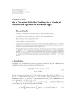
4.2. Software platform
The software platform enables the distributed execution of
applications. It comprises the library functions and the run-
time environment. The software platform on hardware is
presented in Figure 3.
The library functions include various DSP and data pro-
cessing functions (DCT, error checking, encryption) that
can be used in the UML application models. In addition
to the software-implemented algorithms, the library com-
prises software drivers to access their hardware accelerators
and other hardware components, for example the radio in-
terface.
The run-time environment consists of a real-time op-
erating system (RTOS) application programming interface
(API), interprocessor communication (IPC) support, state
machine scheduler, and queues for signal passing between
application processes. RTOS API implements thread c reation
and synchronization services through a standard interface.
Consequently, different operating systems can be used on dif-
ferent CPUs. Currently, all CPUs run a local copy of eCos
RTOS [41].
Distributed execution requires that information about
the process mapping is included in the generated software.
An application distributor tool parses this information au-
tomatically from the UML mapping model and creates the
6 EURASIP Journal on Embedded Systems
corresponding software codes. The codes include a mapping
table that defines on which processing element each process
groupistobeexecuted.
4.2.1. Scheduling of a pplication processes
When an RTOS is used, processes in the same process group
of TUT-profile are executed in the same thread. The pri-
ority of the g roups (threads) can be specified in the map-
ping model, and processes with real-time requirements can
be placed in higher priority threads. The execution of pro-
cesses within a thread is scheduled by an internal state ma-
chine scheduler. This schedule is nonpreemptive, meaning
that state transitions cannot be interrupted by other transi-
tions. The state machine scheduler is a library component,
automatically generated by the UML tools.
Currently, the same generated program code is used for
all CPUs in the system, which enables each CPU to execute all
processes of the application. When a CPU starts execution,
it checks the mapping table to decide which process groups
(threads) it should activate; the rest of groups remains inac-
tive on the particular CPU, as shown in Figure 3.
4.2.2. Signal passing for application processes
The internal (within a process g roup) and external (between
process groups) signal passings are handled by signal passing
functions. They take care that the signal is transmitted to the
correct target process—regardless of the CPU the receiver is
executed on and transparently to the application. The signal
passing functions need services to transfer the UML signals
between different processes. The IPC support provides ser-
vices by negotiating the data transfers over the communica-
tion architecture and handling possible data fragmentation.
On the lower layer, it uses the services of HIBI API to carry
out the data transfers.
The signal passing at run-time is performed using two
signal queues: one for signals passed inside the same thread
and the other for signals from other threads. Processes within
a thread share a common signal queue (included in state ma-
chine scheduler in Figure 3). When a signal is received, it is
placed to the corresponding queue. When the state machine
scheduler detects that a signal is sent to a process residing
on a different CPU, the signal passing functions transmit the
signal to the signal queue on the receiving CPU.
4.2.3. Dynamic mapping
ThecontextofaUMLprocess(statemachine)iscompletely
defined by its current state and the internal variables. Since
all CPUs use the same generated program code, it is possi-
ble to remap processes between processing elements at run
time without copying the application codes. Hence, the op-
eration involves transferring only the process contexts and
signals between CPUs, and updating the mapping tables.
Fast dynamic remapping is beneficial, for example, in
power management, and in capacity management for appli-
cations executed in parallel on the same resources. During
low lo ad conditions, all processes can be migrated to sin-
gle CPU and shut-down the rest. The processing power can
be easily increased again when application load needs. An-
other benefit is the possibility to explore different mappings
with real-time execution. This offers either speedup or accu-
racy gains compared to simulation-based or analytical explo-
ration. The needed monitoring and diagnostic functionality
are automatically included with Koski tools.
An initial version for automated remapping at run time
according to workload is being evaluated. The c urrent im-
plementation observes the processor and workload statistics,
and remaps the application processes to the minimum set of
active processors. The implementation and results are dis-
cussed in detail in [42].
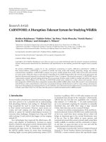
The dynamic mapping can be exploited also manually at
run time using the execution monitor presented in Figure 4.
The monitor shows the processors implemented on FPGA,
application processes executed on the processors, and the
utilization of each processor. A user can “drag-and-drop”
processes from one processor to another to exploit dynamic
mapping. In addition to the processor utilization, the mon-
itor can show also other statistics, such as memory usage
and bus utilization. Furthermore, application-specific diag-
nostic data can be shown, for example user data throughput
in WLAN.
5. WIRELESS VIDEO TERMINAL
The wireless video terminal integr ates two complementary
subsystems: video encoder and WLAN communications sub-
systems. An overview of the wireless terminal is presented in
Figure 5. In this sec tion we present the subsystems and their
UML application models, the hardware architecture and its
UML architecture model, and finally, the mapping of subsys-
tems to the architecture, and the corresponding UML map-
ping model.
The basic functionality of the terminal is as follows. The
terminal receives raw image frames from PC over an Ether-
net connection in IP packets, or from a camera directly con-
nected to the terminal. The TCP/IP stack unwraps the raw
frame data from the IP packets. The raw frame data is for-
warded to the video encoder subsystem that produces the
encoded bit stream. The encoded bit stream is forwarded to
the communication subsystem that wraps the bit stream in
WLAN packets and sends them over w ireless link to a re-
ceiver .
The composite structure of the whole terminal is pre-
sented in Figure 6. This comprises the two subsystems and
instantiates processes for bit stream packaging, managing
TUTMAC, and accessing the external radio. The bit stream
packaging wraps the encoded bit stream into user packets
of TUTMAC. Class MngUser acts as a management instance
that configures the TUTMAC protocol, that is, it defines the
terminal type (base station or portable terminal), local sta-
tion ID, and MAC address. Radio accesses the radio by con-
figuring it and initiating data transmissions and receptions.
Petri Kukkala et al. 7
Figure 4: User interface of the execution monitor enables “drag-and-drop style” dynamic mapping.
TCP/IP stack
Video encoder
subsystem
Wireless communications
subsystem
Ethernet
interface
Camera
interface
Radio interface
Wireless video terminal
Raw i mages
from PC
(IP packets)
Raw images
from camera
Encoded
bit-stream
over WLAN
Figure 5: Overview of the wireless video terminal.
5.1. Video encoder subsystem
The video encoder subsystem implements an H.263 encoder
in a function-parallel manner. Each function is implemented
as a single UML process with well-defined interfaces.
As TUT-profile natively supports function parallelism,
each process can be freely mapped to any (general-purpose)
processing element even at run time. Further, the processes
communicate using signals via their interfaces, and they have
no shared (global) data.
The composite structure of the H.263 encoder UML
modelispresentedinFigure 7. The application model for
the encoder contains four processes. Preprocessing takes in
frames of raw images and divides them into macroblocks.
Discrete cosine transformation (DCT ) transforms a mac-
roblock into a set of spatial frequency coefficients. Quantiza-
tion quantizes the coefficients. Macroblock coding (MBCod-
ing) does entropy coding for macroblocks, and produces an
encoded bit stream.
The functionality of the processes is obtained by reusing
the C codes from a reference H.263 intraframe encoder. The
control structure of the encoder was reimplemented using
UML statecharts, but the algorithms (DCT, quantization,
coding) were reused as such. Thus, we were able to reuse over
90% of the reference C codes. The C codes for the algorithm
implementations were added to the function library.
First stage in the modeling of the encoder was defining
appropriate interfaces for the processes. For this, we defined
data types in UML for frames, macroblocks, and bit stream,
as presented in Figure 8(a). We chose to use C type of ar-
rays (CArray) and pointers (CPtr) to store and access data,
because in this way full compatibility with the existing algo-
rithm implementations was achieved.
The control structures for the encoder were implemented
using UML statecharts. Figure 8(b) presents the statechart
implementation for the preprocessing. As mentioned before,
the main task of the preprocessing is to divide frames into
macroblocks. Further, the presented statechart implements
flow control for the processing of created macroblocks. The
flow control takes care that sufficientamountofmacroblocks
(five macroblocks in this case) is pipelined to the other en-
coder processes. This enables function-parallel processing as
there are enough macroblocks in the pipeline. Also, this con-
trols the size of signal queues as there are not too many
8 EURASIP Journal on Embedded Systems
pIn
<<Application>>
enc : H263::Encoder
pIn pOut
<<ApplicationProcess>>
bs : BitstreamPackaging
pIn pOut
<<Application>>
mac : Tutmac::TUTMAC
pMngUser
pUser pPhy
<<ApplicationProcess>>
MngUser : MngU ser
pTutmac
<<ApplicationProcess>>
Radio : Radio
pTutmac
Figure 6: Top-level composite structure of the wireless video terminal.
pIn
<<ApplicationProcess>>
pp : Preprocessing[1]/ 1
pFrameIn pMBOut
pMBControl
<<ApplicationProcess>>
dct : DCT[1]/1
pMBIn pMBOut
<<ApplicationProcess>>
q : Quantization[1]/1
pMBIn pMBOut
pMBControl
<<ApplicationProcess>>
code : MBCoding[1]/1
pMBIn pBitStreamOut pOut
Figure 7: Composite structure of the video encoder.
macroblocks buffered within the processes, which increases
dynamic memory usage.
5.2. WLAN communications subsystem
The WLAN communications subsystem implements a pro-
prietary WLAN MAC protocol, called TUTMAC. It utilizes
dynamic reservation time division multiple access (TDMA)
to share the wireless medium [43]. TUTMAC solved the
problems of scalability, QoS, and security present in stan-
dard WLANs. The wireless network has a centrally controlled
topology, where one base station controls and manages mul-
tiple portable terminals. Several configurations have been de-
veloped for different purposes and platforms. Here we con-
sider one configuration of the TUTMAC protocol.
The protocol contains data processing functions for
cyclic redundancy check (CRC), encryption, and fragmen-
tation. CRC is performed for headers with CRC-8 algorithm,
and for payload data with CRC-32 algorithm. The encryp-
tion is performed for payload data using an advanced en-
cryption system (AES) algorithm. The AES algorithm en-
crypts payload data in 128-bit blocks, and uses an encryption
key of the same size. The fragmentation divides large user
packets into se veral MAC frames. Further, processed frames
arestoredinaframebuffer. The TDMA scheduler picks the
stored frames and transmits them in reser ved time slots. The
data processing is performed for every packet sent and re-
ceived by a terminal. When the data throughput increases
and packet interval decreases, several packets are pipelined
and simultaneously processed by different protocol func-
tions.
The TDMA scheduling has to maintain accurate frame
synchronization. Tight real-time constraints are addressed
and prioritized processing is needed to guarantee enough
performance (throughput, latency) and accuracy (TDMA
scheduling) for the protocol processing. Thus, the perfor-
mance and parallel processing of protocol functions become
significant issues. Depending on the implementation, the al-
gorithms may also need hardware acceleration to meet the
delay bounds for data [39]. However, in this case we consider
a full software implementation, because we want to empha-
size the distributed software execution.
The top-level class composition of the TUTMAC pro-
tocolispresentedinFigure 9(a). The top-level class (TUT-
MAC) introduces two processes and four classes with fur-
ther composite structure, each introducing a number of pro-
cesses, as presented in the hierarchical composite structure
in Figure 9(b). Altogether, the application model of TUT-
MAC introduces 24 processes (state machines). The proto-
col functionality is fully defined in UML, and the target ex-
ecutables are obtained with automatic code generation. The
implementation of the TUTMAC protocol using UML is de-
scribed in detail in [7, 8].
5.3. Hardware architecture
The available components of the used platform are presented
in a class diagram in Figure 10(a). The available compo-
nents include different versions of Nios II (fast, standard
economy [44], I/O with Ethernet), hardware accelerators
(CRC32, AES), WLAN radio interface, and HIBI for on-chip
communications. Each component is modeled as a class with
an appropriate stereotype containing tagged values that pa-
rameterize the components (type, frequency). All processing
elements have local memories and, hence, no memories are
shown in the figure.
The architecture model for the wireless video terminal
is presented in Figure 10(b). The architecture instantiates a
set of components introduced by the platform. Further, it
defines the communication architecture which, in this case,
comprises one HIBI segment interconnecting the instanti-
ated components.
5.4. Mapping of subsystems
As presented above, the subsystems of the terminal are mod-
eled as two distinct applications. Further, these are integrated
Petri Kukkala et al. 9
<<interface>>
iFrame
<<interface>>
iMB
signal Frame (frame: FrameData) signal MB (cbp: sint32, data: MBData)
<<interface>>
iBitStream
<<interface>>
iFlowControl
signal BitStream (bitcount: uint16, bitstream: BitStreamData) signal MBEncoded()
// Frame data types
syntype FrameData
= CArray<uint8, 38016>;
syntype FramePtr
= CPtr<uint8>;
// Macroblock types
syntype MBData
= CArray<sint16, 448>;
syntype MBPtr
= CPtr<sint16>;
// Bitstream types
syntype BitStreamData
= CArray<uint8, 4096>;
syntype BitStreamPtr
= CPtr<uint8>;
MBType
+cbp:sint32
+data:MBPtr
(a)
∗
(Idle) Idle
Frame Frame(framedata) MBEncoded()
send mb
flowControl
−−;
xMB
= 0;
yMB
= 0;
flowControl++;
mb.data
= cast<MBPtr >(mbdata);
frameptr
= cast<FramePtr >(framedata);
memoryLoadMB (yMB, xMB, frameptr, mb);
flow
control
H
MB(0, mbdata)
via pOut
flowControl > 0xMB++;
true false
xMB < COLUMNS
send
mb
Wai t
mb ack
true else
FrameData framedata;
MBType mb
= new MBTy pe ();
MBData mbdata;
FramePtr frameptr;
sint32 xMB;
sint32 yMB;
int i;
int j;
Integer flowControl
= 5;
const Integer ROWS
= 9;
const Integer COLUMNS
= 11;
Wai t
mb ack
MBEncoded()
flowControl++;
send
mb flow control
xMB
= 0;
yMB++;
yMB < RO WS
true else
Idle
(b)
Figure 8: Detailed views of the encoder implementation in UML: (a) interfaces and data types of the video encoder, and (b) statechart
implementation for the preprocessing.
together in a top-level application model that gathers the all
functional components of the terminal.
Altogether, the terminal comprises 29 processes that are
mapped to an architecture. One possible mapping model
is presented in Figures 11(a) and 11(b).Eachprocess
is grouped to one of the eight process groups, each of
which mapped to a processing element. Note that the pre-
sented mapping illustrates also the mapping of processes to
10 EURASIP Journal on Embedded Systems
<<Application>>
Tutmac
Protocol
ui dp ss rca mng rmng
11
UserInterface DataProcessing ServiceSupport RadioChannelAccess
<<ApplicationComponent>>
Management
<<ApplicationComponent>>
RadioManagement
(a)
Composite structure diagram Diagram1
pUser
Class UserInterface
pUser
<<ApplicationProcess>>
msduRec: MSDUReception[1]/1
pFlowControl pData
pMng
pUser
<<ApplicationProcess>>
msduDel:MSDUDelivery[1]/1
pData
pMng
pFlowControl pData pMng
Composite structure diagram Diagram1
pFlowControl
Class ServiceSupport
pData
pMng
pIn
<<ApplicationProcess>>
addcrc: AddCRC32[1]/1
pOut
pFlowControl pUpData pMng
<<ApplicationProcess>>
fb: FrameBuffer[1]/1
pChannelAccess
pDownData
pOut
<<ApplicationProcess>>
checkcrc: CheckCRC32[1]/1
pIn
pChannelAccess
Composite structure diagram Diagram1 Class RadioChannellAccess
pData
pRMng
RMngPort
<<ApplicationProcess>>
scheduler: Scheduler[1]/1
DataPort
DataPort
RadioPort
RMngPort SchedulerPort
<<ApplicationProcess>>
ri: RadioInterface[1]/1
PhyPort CRCPort
pPhy
<<ApplicationProcess>>
crc8: CRC8[1]/1
RadioPort
Composite structure diagram Diagram1 Class TUTMAC
pUser pMngUser
pUser
ui: UserInterface
pMng
pFlowControl pData
pMngUser
pUI
<<ApplicationProcess>>
mng: Management[1]/1
pSS
pRMng
pDataUp
dp: DataProcessing
pDataDown
pFlowControl pData
ss: ServiceSupport
pMng
pChannelAccess
pData
rca: RadioChannelAccess
pPhy
pRMng
pPhy
pMng
<<ApplicationProcess>>
rmng: RadioManagement[1]/1
pChannelAccess
pPhy
Composite structure diagram Diagram1 Class DataProcessing
pDataUp
pIn
pIn
pIn
pIn
pIn
pOut
pOut
pOut
pOut
pOut
<<ApplicationProcess>>
addIntegrity: AddIntegrity[1]/1
<<ApplicationProcess>>
encrypt: Encrypt[1]/1
<<ApplicationProcess>>
frag: Fragmentation[1]/1
<<ApplicationProcess>>
uu2mu: UserUnit2MACUnit[1]/1
<<ApplicationProcess>>
dup: Duplicator[1]/1
<<ApplicationProcess>>
checkIntegrity: CheckIntegrity[1]/1
<<
ApplicationProcess>>
decrypt: Decrypt[1]/1
<<ApplicationProcess>>
defrag: Defragmentation[1]/1
<<ApplicationProcess>>
mu2uu: MACUnit2UserUnit[1]/1
<<ApplicationProcess>>
duphand: DuplicateHandling[1]/1
pIn
pIn
pIn
pIn
pIn
pOut
pOut
pOut
pOut
pOut
pDataDown
(b)
Figure 9: Hierarchical implementation of the TUTMAC protocol: (a) top-level class composition, and (b) hierarchical composite structure.
Table 2: Static memor y requirements for a single CPU.
Software component Code (bytes) Code (%) Data (bytes) Data (%) Total (bytes) Total (%)
Generated code 28 810 20.52 56 376 43.59 85 186 31.58
Library functions
31 514 22.45 49 668 38.40 81 182 30.10
State machine scheduler
16 128 11.49 3 252 2.51 19 380 7.18
Signal passing functions
4 020 2.86 4 0.00 4 024 1.49
HIBI API
2 824 2.01 4 208 3.25 7 032 2.61
IPC support
2 204 1.57 449 0.35 2 653 0.98
Device drivers
1 348 0.96 84 0.06 1 432 0.53
eCos
53 556 38.14 15 299 11.83 68 855 25.53
Total software 140 404 100.00 129 340 100.00 269 744 100.00
Petri Kukkala et al. 11
<<PlatformComponent>>
Nios
II f
<<PlatformComponent>>
Nios II s
<<PlatformComponent>>
Nios II e
<<PlatformComponent>>
Nios II io
<<PlatformComponent>>
Type
= “general purpose processor”
Frequency
= 50
<<PlatformComponent>>
Type
= “general purpose processor”
Frequency
= 50
<<PlatformComponent>>
Type
= “general purpose processor”
Frequency
= 50
<<PlatformComponent>>
Frequency
= 50
Type
= “general purpose processor”
<<PlatformComponent>>
Intersil
WLAN radio
<<PlatformComponent>>
CRC32
<<PlatformComponent>>
AES
<<PlatformComponent>>
HIBISegment
<<PlatformComponent>>
Type
= “communication interface”
Frequency
= 25
<<PlatformComponent>>
Type
= “hardware accelerator”
Frequency
= 50
<<PlatformComponent>>
Type
= “hardware accelerator”
Frequency
= 50
<<PlatformComponent>>
Type
= “communication interface”
Frequency
= 50
(a)
<<ProcessingElement>>
CPU1 : Nios
II f
<<ProcessingElement>>
CPU2 : Nios II f
<<ProcessingElement>>
CPU3 : Nios II f
<<ProcessingElement>>
CPU4 : Nios II f
<<ProcessingElement>>
IO cpu : Nios II io
<<ProcessingElement>>
CRC : CRC32
<<ProcessingElement>>
AES : AES
<<ProcessingElement>>
RadioInterface : Intersil
WLAN radio
<<HIBISegment>>
Segment1 : HIBISegment
HIBI
port HIBI port HIBI port HIBI port HIBI port HIBI port HIBI port
HIBI
port
Port1
(b)
Figure 10: Platform components are (a) modeled as UML classes and parameterized using appropriate s tereotypes, and (b) instantiated in
the architecture model.
Table 3: Average processing times of the TUTMAC components for
a single frame.
Component Processing time (ms) Processing time (%) Note
msduRec 3.63 13.13 —
addIntegrity
0.94 3.38 —
encrypt
14.56 52.61 —
frag
0.66 2.39 —
uu2mu
4.10 14.80 (1)
addcrc
2.17 7.85 (1)
fb
0.64 2.30 (1)
ri
0.78 2.81 (1)
crc8
0.20 0.72 (1)
Tota l 27.68 100.00 —
(1) Processing time is for 2 WLAN packets (data is fragmented).
hardware accelerator, although in this case study we use full
software implementation to concentrate the distributed exe-
cution of software.
6. MEASUREMENTS
This section presents the implementation details and perfor-
mance measurements of the wireless video terminal.
Table 4: Average processing times of the video encoder components
for a single frame.
Component Processing time (ms) Processing time (%)
Preprocessing 17.83 9.31
DCT
46.93 24.51
Quantization
68.05 35.55
MBCoding
57.86 30.23
BitstreamPackaging
0.77 0.40
Tota l 191.43 100.00
6.1. Implementation details
The required amount of memory for each software compo-
nent is presented in Table 2. All CPUs functionally have iden-
tical software images that differ in memory and process map-
pings only. Creating unique code images for each CPU was
not considered at this stage of research. However, it is a viable
option, especially, when the dynamic run-time remapping is
not needed. In addition to the static memory needs, the ap-
plications require 140–150 kB of dynamic memory. The dy-
namic memory consumption is distributed among CPUs ac-
cording to processes mapping.
The size of the hardware architecture (five Nios II CPU s,
HIBI, radio interface, AES, CRC-32) is 20 495 adaptive logic
12 EURASIP Journal on Embedded Systems
<<ApplicationProcess>>
Preprocessing
<<ApplicationProcess>>
DCT
<<ApplicationProcess>>
Quantization
<<ApplicationProcess>>
MBCoding
<<ApplicationProcess>>
BitstreamPackaging
<<ApplicationProcess>>
msduRec
<<ApplicationProcess>>
frag
<<ApplicationProcess>>
uu2mu
<<ApplicationProcess>>
dup
<<ApplicationProcess>>
mng
<<ApplicationProcess>>
MngUser
<<ApplicationProcess>>
addcrc
<<ApplicationProcess>>
checkcrc
<<ApplicationProcess>>
addIntegrity
<<ApplicationProcess>>
checkIntegrity
<<ApplicationProcess>>
fb
<<ApplicationProcess>>
ri
<<ApplicationProcess>>
scheduler
<<ApplicationProcess>>
CRC8
<<ApplicationProcess>>
duphand
<<ApplicationProcess>>
mu2uu
<<ApplicationProcess>>
defrag
<<ApplicationProcess>>
msduDel
<<ApplicationProcess>>
rmng
<<ApplicationProcess>>
Radio
<<ApplicationProcess>>
encrypt
<<ApplicationProcess>>
decrypt
<<ProcessGroup>>
Group
CPU1 : Group
<<ProcessGroup>>
Group
CPU3 : Group
<<ProcessGroup>>
Group
CRC : Group
<<ProcessGroup>>
Group
CPU2 : Group
<<ProcessGroup>>
Group
CPU4 : Group
<<ProcessGroup>>
Group
IO cpu : Group
<<ProcessGroup>>
Group
RadioInterface : Group
<<ProcessGroup>>
Group
AES : Group
<<ProcessGrouping>>
<<ProcessGrouping>>
<<ProcessGrouping>>
<<ProcessGrouping>>
<<ProcessGrouping>>
<<ProcessGrouping>>
<<ProcessGrouping>>
<<ProcessGrouping>>
<<ProcessGrouping>>
<<ProcessGrouping>>
<<ProcessGrouping>>
<<ProcessGrouping>>
<<ProcessGrouping>>
<<ProcessGrouping>>
<<ProcessGrouping>>
<<ProcessGrouping>>
<<ProcessGrouping>>
<<ProcessGrouping>>
<<ProcessGrouping>>
<<ProcessGrouping>>
<<ProcessGrouping>>
<<ProcessGrouping>>
<<ProcessGrouping>>
<<ProcessGrouping>>
<<ProcessGrouping>>
<<ProcessGrouping>>
(a)
<<ProcessGroup>>
Group
CPU1 : Group
<<ProcessGroup>>
Group
CPU2 : Group
<<ProcessGroup>>
Group
CPU3 : Group
<<ProcessGroup>>
Group
CPU4 : Group
<<ProcessGroup>>
Group
CRC : Group
<<ProcessGroup>>
Group
AES : Group
<<ProcessGroup>>
Group
RadioInterface : Group
<<ProcessGroup>>
Group
IO cpu : Group
<<ProcessingElement>>
CPU1
<<ProcessingElement>>
CPU2
<<ProcessingElement>>
CPU3
<<ProcessingElement>>
CPU4
<<ProcessingElement>>
CRC
<<ProcessingElement>>
AES
<<ProcessingElement>>
RadioInterface
<<ProcessingElement>>
IO
cpu
<<GroupMapping>>
<<GroupMapping>>
<<GroupMapping>>
<<GroupMapping>>
<<GroupMapping>>
<<GroupMapping>>
<<GroupMapping>>
<<GroupMapping>>
(b)
Figure 11: Mapping models: (a) grouping of processes to the process groups, and (b) mapping of process groups to the architecture.
modules (ALM), which takes 84% of the total capacity on the
used Stratix II FPGA. Further, the hardware (FIFO modules,
configuration bits) takes 760 kb (29%) of the FPGA on-chip
memory. The operating frequency was set to 50 MHz in all
measurements.
6.2. Performance measurements
Table 3 presents the average processing times of the TUT-
MAC components when transmitting a single encoded video
frame. The size of the encoded bit stream per frame was
Petri Kukkala et al. 13
Table 5: Video encoder frame rates and TUTMAC transmission delay with different mappings.
Mapping Frame rate (fps) Transmission delay (ms) Note
Whole terminal on a single CPU 1.70 54.10 (1)
Videoencoderon1CPU,TUTMACon1CPU
2.10 27.70 —
Video encoder on 2 CPUs, TUTMAC on 1 CPU
2.40 27.70 —
Video encoder on 3 CPUs, TUTMAC on 1 CPU
3.00 27.70 —
Video encoder on 4 CPUs, TUTMAC on 1 CPU
2.80 28.00 (1)
(1) One CPU is shared.
1800 B in average. The maximum W LAN packet size is
1550 B, which means that each encoded frame was frag-
mented into two WLAN packets. The total processing time
(27.68 ms) in this case results in a theoretical maximum
throughput of 500 kbps, which is very adequate to transmit
the encoded bit stream.
The processing times for the encoder components are
given in Table 4. DCT, quantization, and macroblock coding
handle frames in macroblocks. The presented values are total
times for a single frame (11
× 9 macroblocks). The total pro-
cessing time (191.43 ms) results in a theoretical maximum
frame rate of 5.2 fps on a single CPU (no parallelization).
The reference C implementation of the encoder (on which
the UML implementation is based) achieved the frame rate
of 4.5 f ps on the same hardware.
The presented times include only computing, but not
communication between processes. The run time overheads
of interprocess communication are currently being evaluated
and optimized. AES and CRC that constitute over 60% of
the frame processing time could also be executed on hard-
ware accelerator. DCT and motion estimation accelerators
for video encoding are currently being integrated.
The frame rate of the video encoder and the transmission
delay of TUTMAC were measured with different mappings.
According to the results presented above, we decided to con-
centrate on the distribution of the video encoder, because
it requires more computing effort. Further, TUTMAC is as-
sumed to oper ate well on a single CPU as the data through-
put is rather low (only few dozen kbps).
The frame rates and transmission delays with different
mappings are shown in Tabl e 5. In the first case, the whole
terminal was mapped to a single CPU. In the second case,
the video encoder and the TUTMAC protocol were executed
on separate CPUs. In the third and fourth cases, the video en-
coder was distributed into two and three CPUs, respectively,
while the TUTMAC protocol was executed on one CPU. Fi-
nally, in the fifth case, the video encoder was executed on
both four CPUs and TUTMAC shared one of the four CPUs.
As mentioned before, remapping does not require hardware
synthesis, or even software compilation.
The measurements revealed that the distributed execu-
tion of the video encoder improves the frame rate, and at the
most ,the frame rate is 3.0 fps on three CPUs. In the fifth case,
the sharing of one CPU increases the workload on that CPU,
which prevents further improvements in frame rate.
The communication overhead between CPUs is the main
reason of the fact that the improvements are lower than in
an ideal case. However, we argue that the achieved results
in performance are very good as the used design method-
ology and tools improve the design efficiency significantly. It
should also be noted that the video encoder is not processor
optimized but is based on fully portable models.
7. CONCLUSIONS
This paper presented the implementation of a wireless video
terminal using UML-based design flow. The terminal com-
prises a function parallel H.263 video encoder and WLAN
subsystem for wireless communications. The whole termi-
nal, including the application and platform, was modeled in
UML, and full design automation was used to the physical
implementation.
The main objective of this work was to study the feasibil-
ity of the used design methodology and tools to implement
a multimedia terminal comprising various subsystems, each
comprises several functional components. This objective was
fulfilled with very pleasant results as the design flow tools
enable extensive design automation in implementation from
high-abstraction level models to a complete multiprocessor
SoC on FPGA. The experiments with the UML-based design
flow proved its suitability and competence in designing also
complex embedded multimedia terminals.
The performance of the video encoding was quite sat-
isfactory as we achieved 3.0 fps without any optimizations
in architecture and communications. Slightly better perfor-
mance can be achieved using reference C implementation of
the encoder. The reduced performance is the cost of using
UML and design automation, but is highly accepted as we
gain significant improvement in design efficiency.
Capability to rapid prototyping and easy modifications
to the applications is one of the major improvements in the
design process as the fully automated design flow signifi-
cantly reduces the amount of “low-level” coding. Further,
the clear constructs in modeling, due to the well-defined and
practical profile, enable rather easy integration of complex
subsystems, as shown in this case study.
The future work with the design methodology includes
enhanced support for nonfunctional constraints and more
detailed hardware modeling. In addition, IPC functions and
memory architecture will be optimized to allow more effi-
cient parallelization. The encoder could be implemented in
data or temporal parallel fashion to enhance the scalabil-
ity and performance. Further, the application development
will include the implementation of the full H.263/MPEG-4
14 EURASIP Journal on Embedded Systems
encoder, that is, adding the motion estimation functionality
to enable encoding the interframes also.
REFERENCES
[1] L. Lavagno, G. Martin, and B. Selic, Eds., UML for Real: Design
of Embedded Real-Time Systems, Kluwer Academic, New York,
NY, USA, 2003.
[2] R. Soley, “Model Driven Architecture,” November 2000, Ob-
ject Management Group (OMG), white paper.
[3] R. B. France, S. Ghosh, T. Dinh-Trong, and A. Solberg,
“Model-driven development using UML 2.0: promises and
pitfalls,” Computer, vol. 39, no. 2, pp. 59–66, 2006.
[4] Object Management Group (OMG), “MDA Guide (Version
1.0.1),” June 2003.
[5] T. Kangas, P. Kukkala, H. Orsila, et al., “UML-based multi-
processor SoC design framework,” ACMTransactionsonEm-
bedded Computing Systems, vol. 5, no. 2, pp. 281–320, 2006.
[6] O bject Management Group (OMG), “Unified Modeling Lan-
guage (UML) Superstructure Specification (Version 2.0),” Au-
gust 2005.
[7] P. Kukkala, V. Helminen, M. H
¨
annik
¨
ainen, and T. D.
H
¨
am
¨
al
¨
ainen, “UML 2.0 implementation of an embedded
WLAN protocol,” in Proceedings of the 15th IEEE International
Symposium on Personal, Indoor and Mobile Radio Communi-
cations (PIMRC ’04), vol. 2, pp. 1158–1162, Barcelona, Spain,
September 2004.
[8] P. Kukkala, M. H
¨
annik
¨
ainen, and T. D. H
¨
am
¨
al
¨
ainen, “De-
sign and implementation of a WLAN terminal using UML 2.0
based design flow,” in Embedded Computer Systems: Architec-
tures, Modeling, and Simulation, vol. 3553 of Lecture Notes in
Computer Science, pp. 404–413, Springer, New York, NY, USA,
2005.
[9] G. Martin, L. Lavagno, and J. Louis-Guerin, “Embedded UML:
a merger of real-time UML and co-design,” in Proceedings of
the 9th International Workshop Hardware/Software Codesign,
pp. 23–28, Copenhagen, Denmark, April 2001.
[10] R. Chen, M. Sgroi, L. Lavagno, G. Martin, A. Sangiovanni-
Vincentelli, and J. Rabaey, “UML and platform-based design,”
in UML for Real: Design of Embedded Real-Time Systems,pp.
107–126, Kluwer Academic, Norwell, Mass, USA, 2003.
[11] Object Management Group (OMG), “UML Profile for
Schedulability, Performance, and Time Specification (Version
1.1),” January 2005.
[12] B. Selic, “Using UML for modeling complex real-time sys-
tems,” in Proceedings of Languages, Compilers, and Tools for
Embedded Systems (LCTES ’98), vol. 1474 of Lecture Notes in
Computer Science, pp. 250–260, Montreal, Canada, June 1998.
[13] P. Green, M. Edwards, and S. Essa, “HASoC - towards a new
method for system-on-a-chip development,” Design Automa-
tion for Embedded Systems, vol. 6, no. 4, pp. 333–353, 2002.
[14] S. Pllana and T. Fahringer, “On customizing the UML for
modeling performance-oriented applications,” in Proceedings
of the 5th International Conference on the Unified Modeling
Language, vol. 2460 of Lecture Notes in Computer Science,pp.
259–274, Springer, Dresden, Germany, September-October
2002.
[15] Object Management Group (OMG), “UML Profile for System
on a Chip (SoC) Specification (Version 1.0),” June 2006.
[16] Object Management Group (OMG), “OMG Systems Model-
ing Language (SysML) Specification,” June 2006.
[17] K. Olukotun, B. A. Nayfeh, L. Hammond, K. Wilson, and K.
Chang, “The case for a single-chip multiprocessor,” in Proceed-
ings of the 7th International Symposium on Architectural Sup-
port for Programming Languages and Operating Systems (ASP-
LOS ’96), pp. 2–11, Cambridge, Mass, USA, October 1996.
[18] M. Kaiserswerth, “The parallel protocol engine,” IEEE/ACM
Transactions on Networking, vol. 1, no. 6, pp. 650–663, 1993.
[19] I. Ahmad, Y. He, and M. L. Liou, “Video compression with
parallel processing,” Parallel Computing,vol.28,no.7-8,pp.
1039–1078, 2002.
[20] I. Agi and R. Jagannathan, “A portable fault-tolerant paral-
lel s oftware MPEG-1 encoder,” Multimedia Tools and Applica-
tions, vol. 2, no. 3, pp. 183–197, 1996.
[21] J. Nang and J. Kim, “Effective parallelizing scheme of MPEG-1
video encoding on ethernet-connected workstations,” in Pro-
ceedings of the Conference on Advances in Parallel and Dis-
tributed Computing, pp. 4–11, Shanghai, China, March 1997.
[22] M. J. Garrido, C. Sanz, M. Jim
´
enez, and J. M. Menasses, “An
FPGA implementation of a flexible architecture for H.263
video coding,” IEEE Transactions on Consumer Electronics,
vol. 48, no. 4, pp. 1056–1066, 2002.
[23] O. Cantineau and J D. Legat, “Efficient parallelisation of an
MPEG-2 codec on a TMS320C80 video processor,” in Proceed-
ings of the International Conference on Image Processing (ICIP
’98), vol. 3, pp. 977–980, Chicago, Ill, USA, October 1998.
[24] S. Bhattacharjee, S. Das, D. Saha, D. R. Chowdhury, and P. P.
Chaudhuri, “A parallel architecture for video compression,” in
Proceedings of the 10th IEEE International Conference on VLSI
Design, pp. 247–252, Hyderabad, India, January 1997.
[25] S. M. Akramullah, I. Ahmad, and M. L. Liou, “Performance
of software-based MPEG-2 video encoder on parallel and dis-
tributed systems,” IEEE Transactions on Circuits and Systems
for Video Technology, vol. 7, no. 4, pp. 687–695, 1997.
[26] N. H. C. Yung and K K. Leung, “Spatial and temporal data
parallelization of the H.261 video coding algorithm,” IEEE
Transactions on Circuits and Syste ms for Video Technology,
vol. 11, no. 1, pp. 91–104, 2001.
[27] O b ject Management Group (OMG), “The Common Object
Request Broker Specification (Version 3.0),” March 2004.
[28] Object Management Group (OMG), “UML Profile for
CORBA Specification (Version 1.0),” April 2002.
[29] D. C. Schmidt and F. Kuhns, “An overview of the real-time
CORBA specification,” Computer, vol. 33, no. 6, pp. 56–63,
2000.
[30] U. Brinkschulte, T. Ungerer, A. Bechina, et al., “A microkernel
middleware architecture for distributed embedded real-time
systems,” in Proceedings of the 20th IEEE Symposium on Re-
liable Distributed Systems (SRDS ’01), pp. 218–226, New Or-
leans, La, USA, October 2001.
[31] C. Gill, V. Subrarnonian, J. Parsons, et al., “ORB middleware
evolution for networked embedded systems,” in Proceedings of
the 8th International Workshop on Object-Oriented Real-Time
Dependable Systems (WORDS ’03), pp. 169–176, Guadalajara,
Mexico, January 2003.
[32] T. Rintaluoma, O. Silven, and J. Raekallio, “Interface overheads
in embedded multimedia software,” in Proceedings of the 6th
International Workshop on Architectures, Modeling, and Simu-
lation (SAMOS ’06), vol. 4017 of Lecture Notes in Computer
Science, pp. 5–14, Springer, Samos, Greece, July 2006.
[33] M. Born, E. Holz, and O. Kath, “A method for the design
and development of distributed applications using UML,”
in Proceedings of the 37th International Conference on Tech-
nology of Object-Oriented Languages and Systems (TOOLS-
PACIFIC ’00), pp. 253–264, Sydney, Australia, November
2000.
Petri Kukkala et al. 15
[34] P. Kukkala, J. Riihim
¨
aki, M. H
¨
annik
¨
ainen, T. D. H
¨
am
¨
al
¨
ainen,
and K. Kronl
¨
of, “UML 2.0 profile for embedded system de-
sign,” in Proceedings of Design, Automation and Test in Europe
(DATE ’05), vol. 2, pp. 710–715, Munich, Germany, March
2005.
[35] P. Kukkala, M. H
¨
annik
¨
ainen, and T. D. H
¨
am
¨
al
¨
ainen, “Perfor-
mance modeling and reporting for the UML 2.0 design of em-
bedded systems,” in Proceedings of International Symposium
on Syste m-on-Chip (SoC ’05), pp. 50–53, Tampere, Finland,
November 2005.
[36] M. Bj
¨
orkander, “Graphical programming using UML and
SDL,” Computer, vol. 33, no. 12, pp. 30–35, 2000.
[37] S. Gnesi, D. Latella, and M. Massink, “Modular semantics for
a UML statechart diagrams kernel and its extension to multi-
charts and branching time model-checking,” JournalofLogic
and Algebraic Programming, vol. 51, no. 1, pp. 43–75, 2002.
[38] T. Arpinen, P. Kukkala, E. Salminen, M. H
¨
annik
¨
ainen, and T.
D. H
¨
am
¨
al
¨
ainen, “Configurable multiprocessor platform with
RTOS for distributed execution of UML 2.0 designed applica-
tions,” in Proceedings of Design, Automation and Test in Europe
(DATE ’06), vol. 1, pp. 1–6, Munich, Germany, March 2006.
[39] M. Set
¨
al
¨
a, P. Kukkala, T. Arpinen, M. H
¨
annik
¨
ainen, and T. D.
H
¨
am
¨
al
¨
ainen, “Automated distribution of UML 2.0 designed
applications to a configurable multiprocessor platform,” in
Proceedings of the 6th International Workshop on Architectures,
Modeling, and Simulation (SAMOS ’06), vol. 4017 of Lecture
Notes in Computer Science, pp. 27–38, Springer, 2006.
[40] E. Salminen, T. Kangas, T. D. H
¨
am
¨
al
¨
ainen, J. Riihim
¨
aki, V.
Lahtinen, and K. Kuusilinna, “HIBI communication network
for system-on-chip,” Journal of VLSI Signal Processing Systems
for Signal, Image, and Video Technology,vol.43,no.2-3,pp.
185–205, 2006.
[41] A. Massa, Embedded Software Development with eCos,
Prentice-Hall Professional Technical Reference, New York, NY,
USA, 2002.
[42] P. Kukkala, T. Arpinen, M. Set
¨
al
¨
a, M. H
¨
annik
¨
ainen, and T. D.
H
¨
am
¨
al
¨
ainen, “Dynamic power management for UML mod-
eled applications on multiprocessor SoC,” in Proceedings of the
IS&T/SPIE 19th Annual Symposium on Electronic Imaging,San
Jose, Calif, USA, January-February 2007.
[43] M. H
¨
annik
¨
ainen, T. Lavikko, P. Kukkala, and T. D.
H
¨
am
¨
al
¨
ainen, “TUTWLAN - QoS supporting wireless net-
work,” Telecommunication Systems, vol. 23, no. 3-4, pp. 297–
333, 2003.
[44] Altera, “Nios II Processor Reference Handbook (Version 6.0),”
May 2006.