Báo cáo hóa học: " Research Article A SOA-Based Embedded Systems Development Environment for Industrial Automation" pdf
Bạn đang xem bản rút gọn của tài liệu. Xem và tải ngay bản đầy đủ của tài liệu tại đây (1.33 MB, 15 trang )
Hindawi Publishing Corporation
EURASIP Journal on Embedded Systems
Volume 2008, Article ID 312671, 15 pages
doi:10.1155/2008/312671
Research Article
A SOA-Based Embedded Systems Development Environment
for Industrial Automation
K. C. Thramboulidis, G. Doukas, and G. Koumoutsos
Electrical and Computer Engineering, University of Patras, 26500 Patras, Greece
Correspondence should be addressed to K. C. Thramboulidis,
Received 1 February 2007; Accepted 15 June 2007
Recommended by Jose L. Martinez Lastra
Currently available toolsets for the development of embedded systems adopt traditional architectural styles and do not cover the
whole requirements of the development process, with extensibility being the major drawback. In this paper, a service-oriented
architectural framework that exploits semantic web is defined. Features required in the development process are defined as web
services and published into the public domain, so as to be used on demand by developers to construct their projects’ specific
integrated development environments (IDEs). The infrastructure required to build a web service-based IDE is presented. Specific
web services are defined and the way these services affect the development process is discussed. Special focus is given on the device
model and the means that such a modelling can significantly improve the development process. A prototype implementation
demonstrates the applicability and usefulness of the proposed demand-led development process in the industrial automation
domain.
Copyright © 2008 K. C. Thramboulidis et al. This is an open access article distributed under the Creative Commons Attribution
License, which permits unrestricted use, distribution, and reproduction in any medium, provided the original work is properly
cited.
1. INTRODUCTION
The state-of-the-art in methodologies, techniques, and tools,
that support the embedded systems development process is
unsatisfactory and many years behind the ones used in the
traditional software development process [1]. Even more,
currently used development technologies do not take into ac-
count the specific needs of embedded systems development
[2]. At the same time, even though the need for embedded
devices increases and becomes more demanding, their devel-
opment process is becoming more and more complicated by
the increasing tendency to shift functionality and complexity
from hardware to software.
Software engineering practices such as component-based
and model-driven development are already exploited to de-
velop distributed embedded systems. Descriptions of ready-
to-use software and hardware components that are required
for the model-driven development of embedded devices are
already available on the web. Web browsers and search en-
gines provide the only means to search for the required hard-
ware or software components, as far as this information is
constructed in the current traditional way, that is, using pre-
sentation languages such as HTML in the best case. It is very
difficult if not impossible for this information to be utilized
by integrated development environments (IDEs) to semiau-
tomate the development process.
On the other hand, it is almost impossible for one
methodology and one toolset to cover the whole range of
embedded systems [1], even though a number of component
models [3] evolved during last years to address the specific
requirements of their development process. The embedded
systems’ developer to effectively address the complex devel-
opment process wants to pay only for the resources actually
used to solve the specific problem, and monolithic environ-
mentsdonotcoverthisrequirement.
In this paper, an approach to address the above problems
is presented. Semantic web [4] provides a solution to the first
problem, while service-oriented computing [5] provides the
infrastructure to address the latter. Technologies of the se-
mantic web, such as the Web Ontology Language (OWL) [6],
can be exploited to formalize component descriptions and
make them machine-interpretable so that they can be more
easily analyzed by IDEs to assist the developer in the deci-
sion making processes involved in embedded systems devel-
opment. Using this technology domain models for devices,
device components, software components, and so forth can
2 EURASIP Journal on Embedded Systems
be constructed, uploaded on the web, and utilized by IDEs to
semiautomate the development process. On the other hand,
service-oriented computing provides the infrastructure re-
quired to build an Embedded Systems’ Engineering Support
Environment (eSESE), where the requirements of the devel-
oper for the development process will have the principal role.
The developer, based on these requirements, should be able
to set up and customize a project-specific eSESE by easily in-
tegrating through plug-and-play the desirable features that
should be provided through a service-oriented architecture-
(SOA-) [7] based framework.
A service-oriented architectural framework for the ex-
ploitation of service-oriented computing in the development
process of embedded systems is defined. Features required
in the development process, such as component type, com-
ponent network and system layer editing, implementation
model generation, and component network verification, that
will exploit semantically annotated component descriptions,
aredefinedaswebservices(WSs).Developersareallowed
to implement their own desirable features and incorporate
them into the framework. This provides a powerful and flex-
ible framework for customizing and yet extending the en-
vironment to address the developer’s particular needs. The
developer, instead of buying or developing software com-
ponents and bind them together to form the development
toolset, will construct the project-specific eSESE as an or-
chestration of web services that are only used and bound to-
gether at the time of use of the particular feature of the eS-
ESE.
The device modelling process is used as an example to
present the benefits of the proposed approach. The need for a
device model in the context of this approach is discussed. An
ontology-based framework for such a device model is defined
and a prototype implementation to demonstrate the appli-
cability and usefulness of the proposed approach in the in-
dustrial automation domain is presented. To our knowledge,
there is no other work at the moment towards the direction
of utilizing SOA for the definition of an engineering environ-
ment in the form of an eSESE that will exploit the advantages
of semantic web in service and component specification.
The remainder of this paper is organized as follows. In
the next section, a brief introduction to the basics of SOA
and semantic web is given, along with a reference to their use
in industrial automation. In Section 3, the proposed service-
oriented architectural framework is presented. Section 4 fo-
cuses on device modelling as an example of modelling a con-
stituent component of embedded systems. The need for a
common device model is discussed and a solution to this
problem is proposed. The different scenarios of using the
device model through the system development process are
also presented. A prototype implementation is described in
Section 5 and finally the paper is concluded in the last sec-
tion.
2. BACKGROUND AND RELATED WORK
Software engineering practices such as component-based de-
velopment can be exploited to develop distributed embedded
systems (DESs) for industrial automation. However, main-
stream component models such as DCOM, EJB, and NET are
not suitable for the embedded systems’ domain. A number of
component models evolved during the last years to address
the specific requirements of the development process of em-
bedded systems [3]. Some of these are general purpose, such
as CORBA-CCM [8], PECOS [9], PECT [10], the embed-
ded object architecture [11], DECOS [12], while others are
domain-specific such as the Function Block model defined by
the IEC 61499 standard [13], Ptolemy [14]andGiotto[15]
for the control and automation domain, the Koala model
[16] and the one defined in [1] for consumer electronic soft-
ware, the Rubus component model [17]forresourcecon-
strained real-time systems, the SaveCCM [18] for vehicular
systems, and the PBO [19] for the development of sensor-
based control systems with specialization on reconfigurable
robotics applications.
IDEs supporting the various component models pro-
vide the infrastructure required to exploit the specific mod-
els in the development process. General purpose as well as
domain-specific IDEs are currently available and a number
of projects are on the way for the development of such IDEs.
For example, the DECOS toolset and the Archimedes ESS
[20] have been developed on top of the general modelling en-
vironment (GME) [21]. The former provides a model-based
environment for the embedded systems domain, while the
latter for the control and automation domain.
Today’s IDEs are mainly based on a monolithic propri-
etary toolset and their objective is to assist the developer in
constructing component types and system design diagram
specifications, validating the design specifications, and de-
ploying and executing complex DESs. However, most of the
toolsets cannot fully support an effective development pro-
cess. Embedded systems’ developers for industrial automa-
tion need improved techniques, methodologies, and tools to
better support the analysis, design, debugging, validation,
deployment, and verification of the system and currently
available IDEs do not fully cover these requirements [22].
Even more, developers will have to select the toolset that best
fits their development requirements and, in most of the cases,
the existing or under-development tools do not address all
of these needs. At the same time, it is almost impossible for
one methodology and one toolset to cover the whole range
of DESs, as embedded systems vary considerably in their re-
quirements.
The embedded systems’ developer to effectively address
the complex development process of the next generation ag-
ile DESs in industrial automation wants (a) to pay only for
the resources actually used to solve the specific problem, and
(b) to be able to extend these toolsets to suit project-specific
needs. SOA and semantic web are exploited in this work to
create the infrastructure required to address these require-
ments.
2.1. Service-oriented architectures
Software architectures have emerged as an important dis-
cipline for software engineers that were looking for better
ways to understand their systems and new ways to build
larger, more complex software systems [23]. The software
K. C. Thramboulidis et al. 3
architecture involves, according to Shaw and Garlan, “the de-
scription of elements from which systems are built, interac-
tions among these elements, patterns that guide their com-
position, and constraints on these patterns.”
However, as the level of complexity of today’s systems
is continually increasing, traditional architectures that have
been defined over the last years seem to be reaching their
limit in their ability to enable IT organizations to meet to-
day’s complex set of challenges [23]. Brereton and Budgen
in [24] argue that although component-based development,
one of the recent architectural styles, offers many potential
benefits, such as greater reuse and a commodity-oriented
perspective of software, it also raises several issues that de-
velopers need to consider.
Service-oriented computing [5, 25] and SOA are being
promoted as the next evolutionary approach to address these
problems. SOA, which is not only an architecture but also a
programming model, defines a new way of thinking about
building software systems. A service-oriented architecture is
essentially a collection of services along with an infrastruc-
ture that enables these services to communicate with each
other [26]. This communication can be simple as the case of
simple data passing or as complex as the case of two or more
services coordinating to accomplish a higher layer activity.
A service is a function that is well-defined, self-contained,
and does not depend on the context or state of other services.
A service has many characteristics that an architect must con-
sider and specify as required. Performance, capacity, business
organization, risks and issues, ownership, reliability, security,
business impact, tolerance, service contract, and dependen-
cies constitute a list of characteristics for which a service re-
quires further specification [27]. However, all services do not
require the same level of definition. In any case, the following
two questions “what does the service do”? and “what is the
major functionality required by the user”? should be clearly
answered by the specification of the service. The central role
of the specification of user’s required functionality is the issue
that differentiates SOA from object-orientation [27]. Thus
the primary construct of SOA is the service that represents
how its consumers wish to use the system, while that of object
technology is the object that represents an entity as structure
and behavior.
The concept of service-oriented architecture appeared
from the time CORBA [28] provided the first infrastruc-
ture to integrate applications running on different hetero-
geneous platforms. Faster time-to-market, reduced cost, risk
mitigation, continuous business process improvement, and
process-centric architecture are among the most important
benefits of applying SOA [24]. However, the most important
advantage of SOA for the industrial automation domain is
that it can evolve on existing system investments rather than
requiring a full-scale system re-engineering. Legacy systems
can be encapsulated and accessed via service interfaces, pre-
serving the huge amount of investment in this area.
A service-oriented architecture is essentially a collection
of services along with an infrastructure that enables these ser-
vices to communicate with each other. Web services, which
provide the infrastructure required to connect services to-
gether into a service-oriented architecture, are a collection
of technologies, including XML, SOAP, WSDL, and UDDI,
that can be used to implement a service-oriented architec-
ture. They let you build programming solutions for specific
messaging and application integration problems. The Web
Service Definition Language (WSDL) is expected to become
the de facto standard for describing services in the next few
years. So, defining existing industrial automation systems us-
ing WSDL will allow industry to add agility to their IT envi-
ronments.
Other research groups are already exploiting SOA, web
services, and semantic web in industrial automation [29–
33]. The Global Understanding Environment (GUN) [29]is
a middleware framework used to achieve interoperation, au-
tomation, and integration in building complex industrial au-
tomation systems consisting of components of different na-
ture. Semantic web services and agent technologies are ex-
ploited in GUN to make heterogeneous industrial resources
web-accessible, proactive, and cooperative ready to automat-
ically plan their own behavior, monitor, and correct their
own state, communicate, and negotiate depending on their
role. The Service-Oriented Device Architecture (SODA) [30]
attempts to integrate business systems through a set of ser-
vices that can be reused and combined to address chang-
ing business priorities. According to SODA, a device inte-
gration developer would be responsible for encapsulating de-
vices as services. The SIRENA approach [31] intends to cre-
ate a service-oriented framework for specifying and develop-
ing distributed applications in diverse real-time embedded
computing environments. The use of semantic web services
(sWS) is proposed in [32] to address the challenge of rapid
reconfiguration of manufacturing systems required in order
to evolve and adapt to mass customization. A dynamic on-
tological definition of the generic industrial resource to al-
low flexible management, maintenance, and monitoring of
industrial processes is described in [33].
2.2. Semantic web
Semantic Web [3] is expected to become the next genera-
tion of the web assuming that besides the existing content,
there will be a conceptual layer of machine-understandable
metadata, giving well-defined meaning to the information,
and making it available for processing by software agents.
Next-generation applications will address the interoperabil-
ity problem between heterogeneous systems by exploiting
such metadata to perform resource discovery and integration
based on their semantics.
Ontologies and problem solving methods have become
key instruments for the development of the semantic web
[34]. An Ontology, which is a formal explicit specification
of a shared conceptualization, defines “the basic terms and
relations comprising the vocabulary of a topic area as well
as the rules for combining terms and relations to define ex-
tensions to the vocabulary” [35]. An ontology is a key con-
cept for capturing domain-specific consensual knowledge in
the form of a common vocabulary that allows its sharing
by a group. Classes, relations, formal actions, and instances
are the main components of an ontology. Basic concepts are
represented by classes, while associations between concepts
4 EURASIP Journal on Embedded Systems
eSESE of configuration
repository
Local comp
type repository
Project
repository
Deployment
service
Monitoring
service
Internet
Real-time ORB
IEC-compliant devices
Project
repository
service
Model
editor
WS client
Deployment
service
Project-specific ESS
Device repository
y
Device repository
Comp type repository
Comp type repository
y
WSDL interface
e
e
WSDL interface
e
e
WSDL interface
e
e
WSDL interface
e
e
WSDL interface
e
e
Device
repository
service
Component-
type
repository
service
System
layer
editor
Component
network
editor
Component-
type
editor
IEC61499-
compliant
services
UDDI
UDDI interface
e
e
WSDL interface
e
e
WSDL interface
e
e
Implementation
model
generation
Component
network
verification
service
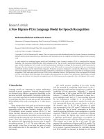
Figure 1: An SOA-based framework for the development of embedded systems.
are represented by relations. Binary relations are used to ex-
press the attributes of the concept. Elements or individuals
are represented as instances and formal axioms are used to
model sentences that are always true. Ontologies promise to
(i) share common understanding of the structure of in-
formation among people or software agents,
(ii) enable reuse of domain knowledge,
(iii) make domain assumptions explicit,
(iv) separate domain knowledge from the operational
knowledge, and
(v) analyze domain knowledge.
The Web Ontology Language (OWL) [6], which has been
optimized to represent structural knowledge at a high level of
abstraction, can be used to formalize web content and create
domain-specific models that can be shared and reused across
the web. Applications that will share these models will gain
the advantage of interoperability.
The idea of modelling the components of embedded
systems using ontologies is not new. Research groups have
constructed such ontologies for various domains, for exam-
ple, the device ontology for the mobile communications do-
main [36]. Most of these works are based on the Fipa-device
specification [37] and propose extensions to cover the spe-
cific domain. Others have identified the significance of the
device modelling in the context of domain-specific frame-
works, for example, in [38] for the definition of a visualiza-
tion approach for collaborative planning systems, and in [39]
for knowledge systematization in the construction process of
knowledge models for manufacturing.
3. THE PROPOSED SERVICE-ORIENTED
FRAMEWORK FOR EMBEDDED SYSTEMS
The proposed SOA-based framework was evolved as an ex-
tension of Corfu [40] and Archimedes system platform [41].
The main objective is to address the restrictions imposed
by traditional embedded systems development environments
and to further extend the provided functionality regard-
ing system layer modelling, as well as deployment and re-
deployment of the application layer components to the run-
time infrastructure.
The service is the basic construct of the proposed archi-
tectural framework as shown in Figure 1. Functions are de-
fined as independent services with well-defined invokable in-
terfaces which can be called in defined sequences to form
the processes required for the development, deployment,
and execution of industrial automation software. Services of
K. C. Thramboulidis et al. 5
the framework implement model definition and model edit-
ing functions, implementation model generation functions,
component-type repository functions for the discovery of re-
quired component types, deployment functions, as well as
monitoring functions.
Services, which should be completely independent of one
another, should operate as black-boxes, without the need for
clients to neither know nor care how these services perform
their function. A service is described by means of WSDL pro-
viding invokable interfaces, which define not the technology
used to implement it but the nature of the service through
the required parameters and the nature of the result. At the
architectural level, it is irrelevant whether these services are
within the same or different address space or even provided
by the same or various vendors. It is also irrelevant what in-
terconnection scheme or protocol is used for the invocation,
or what infrastructure components are required to make the
connection.
It is expected that a great number of services will appear
to provide generic functionality as well as specific functional-
ity required in specialized application domains. In any case,
the definition of services in such an environment is a chal-
lenge since it should be based on many parameters such as
performance, flexibility, maintainability, and reuse. An inter-
esting question not answered yet has to do with the level of
granularity that functions will be mapped to services.
It should be noted that web services in most of the cases
do not meet the resource constraints imposed by embedded
devices and also introduce a great overhead that results in an
order-of-magnitude performance difference comparing with
other service-based technologies such as real-time CORBA.
This is the reason for using web services in the context of this
approach only for the development process.
The proposed framework intends to enable industrial en-
gineers to set up and customize the Engineering Support
System (ESS) that best fits with the needs of their project.
The big advantage of this approach is that these services
are sold and assembled on demand. The industrial engineer,
instead of buying or developing software components and
binding them together to form a custom ESS, will construct
the project-specific ESS as an orchestration of web services.
Selected web services are only used and bound together at
the time of use of the particular feature of the ESS, as shown
in Figure 2, where the conceptual model of the proposed
framework is presented. The term ESS is introduced by the
IEC61499 standard to refer to an enhanced IDE used not only
in the design and implementation, but also in the commis-
sioning as well as the operation phase of industrial automa-
tion systems.
Industrial engineers using the proposed framework can
either assemble their services out of existing ones from the
service layer infrastructure, or define and develop atomic ser-
vices to implement their own desirable features using tradi-
tional development techniques. These services can be later
incorporated in the service layer infrastructure.
This provides a powerful and flexible framework for cus-
tomizing and yet extending the environment to address the
industrial engineer’s particular requirements. It enables the
industrial engineer to construct an ESS by using services by
multiple suppliers to meet the needs of the specific project.
It should be noted that the so-defined development envi-
ronment must include and enforce a methodology that will
clearly prescribe how services and components will be de-
signed and built in order to facilitate reuse, eliminate redun-
dancy, and simplify testing, deployment, and maintenance.
Such a methodology is also required to guide the industrial
engineer through the development process.
The project-specific ESS will be used by embedded sys-
tems’ developers to construct or find the required hard-
ware or software constituent components and use their
models in the development and operational phases of their
systems. One such component is the physical device that
provides storage, processing, and communication capabili-
ties required for the execution of the software components.
The remainder of this section focuses on the modelling of
the device to show the way that the proposed framework en-
hances the effectiveness of the development process of indus-
trial automation embedded systems.
Specific web services are defined to semi-automate
the development process regarding device handling and
more specifically (a) the construction of generic-embedded
boards, (b) the construction of domain-specific devices, (c)
the design process of the system layer as an aggregation of
interconnected devices, (d) the deployment process, and (e)
the verification process. For these web services to interop-
erate through orchestration in order to constitute a coher-
ent ESS, the sharing of common models for the device is a
prerequisite. Technologies of the semantic web are exploited
to formalize device descriptions and make them machine-
interpretable so that they can be more easily used by web ser-
vices to assist the system engineer in device handling. The
next section describes our ontology-based modelling of the
device that satisfies the requirements of this approach.
3.1. Services for device vendors
A specific web service should provide the functionality re-
quired by vendors of embedded boards, shown in (1) of
Figure 2, to create the models of their generic devices in the
form of OWL documents. This functionality is currently pro-
vided by Prot
´
eg
´
e[42] and other ontology tools, but an end-
user-oriented service such as the one we have developed in
our prototype environment is required. This service parses
the ontology and creates a GUI to allow the user to capture
the attributes of the specific device, that is, the embedded
board’s data sheet. The result is an enhanced data sheet in
the form of an OWL document that will be published on the
web ((2) in Figure 2).
Vendors that develop domain-specific devices will dis-
cover, through a semantically annotated UDDI, semantically
annotated WSs that provide the functionality of dynamically
creating GUIs to capture the search criteria for the required
embedded board (3). Such an sWS will exploit the embed-
ded board ontology selected by the user, to dynamically cre-
ate a GUI to allow the user to define the search criteria, that
is, the specific requirements that the requested device should
meet. The created GUI will be in the form of an HTML doc-
ument or in the form of an OWL document if ontologies are
6 EURASIP Journal on Embedded Systems
Design SWS
Deployment SWS
Ve r i fi c a t i on S W S
Customize domain-
specific device SWS
Publish device
SWS
Search for domain-
specific device SWS
Search
for embedded
board SWS
Domain-specific
device ontologies
Distributed
embedded
board
knowledge
bases
Distributed
software
components
knowledge
bases
Semantic web
client-project-
specific ESS
Software component
ontologies
Embedded board
ontologies
Semantic
UDDI
System
layer
model
Application
model
Knowledge layer
Service layer
Embedded
board
vendor
Specific domain
device vendor
3
4
2
1
7
8
6
5
Application
layer
Developer
Publish
Search
Customize
Design
Deploy
Ve r i f y
Distributed
domain-
specific device
knowledge
bases
Figure 2: Conceptual model of the proposed semantic web-based framework.
used to describe GUIs [43]. It should be noted that different
implementation scenarios exist regarding the distribution of
functionality in client-server sides to better exploit the ad-
vantages of semantic web. It is a matter of choice and archi-
tecture as to which functionalities will run locally and this
decision mainly depends on the tools that will evolve to ex-
ploit the semantic web. It is expected that functionalities de-
scribed above will soon be part of the next generation se-
mantic web browsers relieving the developer from the task of
creating sWSs to implement these functionalities.
The user’s search criteria will be formalized using the se-
mantic web rule language (SWRL) [44] that can describe any
kind of restrictions upon ontology concepts. Alternatively, a
queryexpressedinSPARQL[45] or any other query language
can be generated to directly access a knowledge base with
embedded board descriptions. In any case, this sWS inter-
face must be described in OWL-S [46] that provides a stan-
dard vocabulary that can be used to create service descrip-
tions and enable users and software agents to automatically
discover, invoke, compose, and monitor web resources. This
OWL-S defined sWS interface specifies the service grounding
for a dynamically constructed stub client required to invoke
the corresponding service method which is able to locate the
embedded boards that meet the defined search criteria. A set
of device models that meet the search criteria is the result of
this sWS.
Device vendors of a specific domain, following an anal-
ogous process with the one applied by vendors of embedded
boards, will create the owl documents that describe their de-
vices and publish them on the web. Some unclear issues exist
in this process, for example, the way of using the embedded
board model in the process of constructing the specific de-
vice model that has to be supported by the ontology-instance
generation web service.
3.2. Services for the industrial engineer
During the design phase of the system layer, that is, the hard-
ware/software infrastructure required to execute the software
K. C. Thramboulidis et al. 7
application, the industrial engineer searches (4) through the
ESS the web to locate devices that meet required QoSs. These
QoSs are imposed either by the controlled process, for exam-
ple, number and type of process parameters to be sensed or
actuated, or by the components of the software application,
for example, number and functionality of Function Block
types used in an IEC61499-based application. Through se-
mantically annotated web services, the industrial engineer
performs an ontological search based on concepts that are
described in the domain-specific device ontology (5). Access
to basic characteristics of the device is guaranteed since this
information is also included in the device model that was
constructed by the vendor.
Devices are usually described in terms of optional config-
urations. A device, for example, may be configured to have
various types of I/Os or support various operating systems.
A specific web service, that will have the ability of manipu-
lating ontologies relieving the industrial engineer from this
task, will allow the description of the desired configuration
(6) imposed by the specific application. Choices will be made
in a user friendly way and the web service will create the de-
vice model of the defined configuration. This device model
can be downloaded and used for the design of the system
layer.
The use of the device model is also important during
the deployment process (7). That is when decisions must
be made about the distribution of the application’s compo-
nents and the generation of the application implementation
model. During this process, the device model can be auto-
matically updated with the use of rules and rule engines every
time its available resources change, for example, when com-
ponents are downloaded and instances are created. Based on
this, the industrial engineer will always be aware of the re-
maining resources. Specific functionality provided by the ESS
may be utilized to search for possible alternatives that satisfy
the QoSs which are required by the application layer compo-
nents.
Finally, the device model may be utilized through the ver-
ification process (8) of the design model. Device descriptions
in the form of knowledge bases for the specific project will
be stored in the project’s repository and will be exploited by
design-model analysis and verification tools to verify that the
application’s design diagrams, as well as the planned deploy-
ment scenarios, are implementable. Later on, and after the
verification of the design models of the DES, the real devices
can be bought using the appropriate web service and used for
the implementation of the industrial system.
4. DEVICE MODELLING
The embedded application may run on one device but its
components are usually downloaded and executed on a net-
work of interconnected devices. The system layer diagram is
considered as an aggregation of interconnected devices where
interconnecting edges provide the infrastructure required for
the realization of component interactions that cross device
boundaries.
A large number of heterogeneous devices of different
vendors are used for embedded systems development. Since,
these devices can only be handled by proprietary tools that
are provided by their vendors, different tools must be used
today in the life cycle phases of embedded systems in in-
dustrial automation. The need for information exchange be-
tween these tools makes the task of integration very difficult.
Moreover, the large number of different device types and
suppliers within a given embedded system makes the con-
figuration task difficult and time consuming.
It is also clear that the different proprietary device tools
coming from a variety of device vendors cannot be consis-
tently integrated into a coherent toolset. The problem of con-
figuring and parameterizing heterogeneous devices during
the operation diagnosis, parameter tuning, processing pur-
poses, etc. constitutes one of the most important challenges
in the development process.
4.1. The need for device modelling
Descriptions of devices already exist on the web either in the
form of data sheets or in the form of electronic device de-
scription that is a common way of describing programmable
logic controllers (PLCs), that is, electronic devices widely
used for automation of industrial processes. However, since
data sheets are constructed in the traditional way, that is, us-
ing presentation languages such as HTML, embedded system
developers should use their web browsers to search for the
specific devices that meet their requirements. These descrip-
tions are very difficult if not impossible to be utilized by IDEs
to semi-automate the development process.
This problem was recognized very well in the industrial
automation domain where different device models [47–50]
were constructed to address this demand. Device Description
Languages (DDLs) already support the specification of field
devices, with HART DDL [47], Profibus Device Description
[48], and Foundation Fieldbus DDL [49] being among the
most important. These notations are used to represent the
properties of a field device in a proprietary machine-readable
format to be used by proprietary engineering tools during the
development phase. The specification is also used during the
system’s operation phase.
However, there is no common model for the device spec-
ification, and the above notations result in incompatible de-
vice specifications. A device model consistent with current
software engineering practices should be defined to enable
the new generation IDEs to further automate the develop-
ment and deployment process. Operations to be supported
by such a device model include the following.
(i) Select the device that meets the QoS characteristics re-
quired by the software application components.
(ii) Configure the device to meet the requirements of the
current system.
(iii) Semi-automate the deployment and redeployment
processes.
(iv) Create the dynamic model of the device that represents
the device at run time.
The Field Device Markup Language (FDCML) is an
attempt to address the above requirements in the in-
dustrial automation domain. It is an XML-based device
8 EURASIP Journal on Embedded Systems
DeviceDescription DeviceType
Device
+isOf
ResourceBroker
ResourceManager
ResourceType
ResourceInstance
+offers
+offers
ProcessInterfaceRsrcStorageRsrc
DeviceEmulator
ResourceControlPolicy
AccessControlPolicy
Service1
∗
1
∗
1
∗
1
∗
1
∗
0
∗
0
∗
QoSCharacteristic
ActiveRsrc
PassiveRsrcCommunicationRsrcProcessingRsrcUnprotectedRsrc
ProtectedRsrc
QoSValue
ServiceInstance
Figure 3: Part of the constructed device model expressed in UML notation [51].
specification standard [52] for field components to allow a
tool-independent device description whose format can be
used by many applications. FDCML defines the device pro-
file as an aggregation of four basic elements: device-identity,
device-manager, device-function, and application-process. It
has also extensibility elements to provide the appropriate
flexibility for extending the model. However, except from
the fact that the XML schema that is based on is not avail-
able, FDCML does not fully cover the device-application and
device-function elements, which are of great importance to
our approach.
4.2. A UML device model
A prototype model was defined for the device to address
the requirements imposed by the development process. As
shown in Figure 3, where part of this model is shown, the
resource is the key concept in this model. A device is of a
specific DeviceType and is considered as an aggregation of
ResourceInstances, where each ResourceInstance is of a spe-
cific ResourceType. The UML profile for Schedulability, Per-
formance, and Time Specification [53] was utilized for the
modelling of resource so as to represent all the quantitative
aspects of both software and hardware. A resource is con-
sidered as a server that provides one or more services to its
clients [54], with the physical limitations of services to be
represented through QoS attributes. The QoS concept is used
in the context of this framework to establish a uniform ba-
sis for attaching quantifiable information to UML models.
QoS information represents directly or indirectly the phys-
ical properties not only of the application’s components in
the form of required QoS, but also those of the hardware and
software infrastructure used to execute the control applica-
tion (offered QoS).
UML’s extensibility mechanisms can be used to create
a more expressive model for the device. The construct of
stereotype is used to define a specialization of the class con-
struct to add the semantics of the device to the class UML
construct. Additional constraints and tagged values are used
to represent additional attributes of the device. The tagged
value “IEC61499-compliance” is used to define a QoS char-
acteristic of this device that is the class that the specific de-
vice supports regarding its compatibility with the IEC61499
standard. The device model that was created can be used by
device vendors to construct the models of their devices.
We discriminate two approaches for the definition of the
device model from vendors and the whole device modelling
policy:
(i) modelling by instantiation, and
(ii) modelling by extension.
The first one exploits the concept of metamodelling. The
device model for the specific domain, that is, an IEC-61499-
compliant device, is considered as an instance of a generic
model that is the metamodel. The metamodel captures all
these constructs that are required to create device models for
different categories of devices. Assuming such a metamodel,
domain experts can define the IEC61499-compliant device
model as an instance of the generic metamodel.
The second approach is based on a generic device model
that captures the generic attributes and the common behav-
ior of all devices. This model can be specialized by extension
to include the specific attributes and behavior of the mod-
elled kind of devices. The result of this process for the IEC
61499 domain will be an IEC61499-compliant device model.
In both cases, the device vendors should exploit the IEC-
compliant device model to construct the models of their de-
vices as instances of it.
4.3. Using ontologies for device modelling
The device model that was created in this way is impossible to
be used by different tools to share this knowledge and coop-
erate to constitute a coherent toolset for DESs. Technologies
K. C. Thramboulidis et al. 9
Power
Vo l t age
amperage
unit
voltage unit String
∗
amperage
Float
∗
Float
∗
String
∗
Instance
∗
Application
Instance
∗
has firmware Firmware
has
os Instance
∗
Operating System
Software
Environmental
operating
temprature max
operating
humidity max
operating
temprature min
temprature
unit String
∗
operating humidity min Float
∗
Float
∗
Float
∗
Float
∗
Operating System
os
vendor
os
filesystem
os
kernelFirmware has standalone application
∗
String
∗
String
∗
os name String
∗
String
∗
String
∗
os version
···
has application has protocol stack
∗
has driver
∗
Application Protocol Stack Driver
has
power
∗
has environmental
∗
has mechanical
∗
has system
∗
has software
∗
has hardware
∗
has power
∗
Mechanical
Mounting String
∗
Width Float
∗
Float
∗
Float
∗
Float
∗
Length
We ig ht
Height
···
System
sys
power String
∗
String
∗
sys chipset
sys
bus
Any
∗
has bus
Instance
∗
Bus
Instance
∗
has memory Memory
···
Hardware
has
network
Instance
∗
Network
has
IO IOInstance
∗
CPUInstance
∗
Memoryhas memory
has
cpu
Instance
∗
Instance
∗
has storage Storage
···
Embedded Board
has
software SoftwareInstance
∗
has hardware Hardware
has
environmental Environmental
has
mechanical Mechanical
has
power Power
···
Instance
∗
Instance
∗
Instance
∗
Instance
∗
Memory
memory
type
String
∗
String
∗
memory size unit
memory
size
Float
∗
String
∗
Float
∗
clock unit
clock
value
···
CPU
address
bus len
cache
L2
Integer
∗
Integer
∗
Integer
∗
Integer
∗
Boolean
∗
data bus len
cache
L1
has
FPU
···
Bus
bus transfer rate
bus
type
bus
mode
String
∗
String
∗
String
∗
NetworkIO
Storage
storage name
storage
capacity
storage
capacity unit
storage
type
String
∗
String
∗
String
∗
String
∗
RS-232 LPT USB
CAN
Wi-Fi Ethernet
isa isa isa isa isa isa
has
storage
∗
has IO
∗
has network
∗
has bus
∗
has cpu
∗
has cpu
∗
has bus
∗
has memory
∗
has memory
∗
has firmware
∗
has os
∗
has standalone application
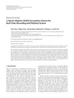
Figure 4: The generic embedded board ontology (part).
of the semantic web, such as the OWL, can be exploited
to formalize device descriptions and make them machine-
readable so that they can be more easily analyzed by IDEs
to assist the developer in the decision making processes in-
volved in system development.
Device vendors instead of developing their own device
model will be able to locate a suitable device model on the
web and simply reuse or extend it. By reusing these mod-
els, different web services can share results and data much
more easily and simplify their integration to form a consis-
tent ESS. The semantic web is used as a platform on which
the domain-specific device model will be created in such a
way that sharing and reusing by many different applications
across the web will be the primary objective. This means that
the proposed framework should provide the infrastructure
required for networking, as well as for merging and align-
ment of ontologies [34], which will be used as enabling tech-
nologies to this direction.
Using this approach, domain-specific models for devices,
but also for other software and hardware artefacts, can be
constructed, uploaded, and linked into the web, so that cus-
tom eSESEs can link and utilize them. The device ontology,
for example, will be defined to represent the common con-
ceptualization that is required to increase the degree of au-
tomation in the system layer development process. This de-
vice ontology should define the meaning of the concepts of
a common device model in a machine-processable format
and should facilitate the processing of information of het-
erogeneous devices in the design phase of the system layer
diagram. It will also describe the device characteristics con-
cerning storage, processing, and communication capabilities
of the device.
4.4. Modelling the device with a networked ontology
To proceed with the device modelling, we define an em-
bedded board ontology that captures the key concepts in-
volved in data sheets of the embedded boards available in the
market, for example, EmCORE-v621, RSC-7820, and PEB-
2530VL. These boards are used by vendors as basis for the
construction of more enhanced devices with specific char-
acteristics for a given embedded application domain. The
FIPA-device ontology [37], which is an early attempt towards
a device model, captures only the basic device concepts pro-
viding a very generic model that can be used as basis for more
detailed device ontologies. Figure 4 presents part of the de-
fined embedded board ontology as visualized in Prot
´
eg
´
e. In
this figure, only the fundamental classes of the proposed on-
tology are depicted along with some of their essential prop-
erties. Although it is not illustrated in the given diagram,
the embedded board ontology can easily exploit the FIPA-
device ontology, since hardware and software classes can be
defined as subclasses of hardware-description and software-
description classes of the FIPA ontology, respectively.
Sinceitisexpectedthatmanydifferent ontologies will
appear to model the embedded board in different ways, on-
tology alignment [55] would allow preservation of the orig-
inal ontologies by establishing different kinds of mappings
or links between these different ontologies. Means should
be provided by the adopted ontology implementation lan-
guage to dynamically interconnect distributed ontologies
and support reuse of already defined concepts. OWL that was
adopted in the context of the proposed framework provides
specific primitives to this direction.
Vendors use generic-embedded boards as basis to con-
struct devices for the specific domain. To create the device
models for the specific domain, a new ontology that should
specialize the embedded board ontology is required. For ex-
ample, the IEC61499-compliant device ontology will be cre-
ated to describe the IEC61499-compliant devices that would
be developed by vendors for the control and automation do-
main. Figure 5 shows a part of this ontology that captures
some of the key concepts of an IEC61499 device, such as
10 EURASIP Journal on Embedded Systems
Embed: Embedded Board
isa
isa
AcquisitionInterface
AcquisitionInterface
acqName String
∗
String
∗
ackBusType
has
Channels Instance
∗
IEC61499Runtime
compliance
class
String
∗
has exec model IEC61499 Execution Model
available
fb types
FB
Type
has
mpp
Instance
∗
Mechanical Process Parameter
available
fb types
∗
has mpp
∗
has exec model
∗
Instance
∗
Instance
∗
AcquisitionChannel
has
AcquisitionInterface Instance
∗
has IEC61499Runtime
∗
isahas AcquisitionInterface
∗
Embed: IO
IEC614991
Device
Embed: Application
emShielding Boolean
∗
Instance
∗
has IEC61499Runtime IEC61499Runtime
has
Channels
∗
FB Ty pe
Mechanical
Process Parameter
mpp
name
mpp
mode
mpp
type
String
∗
String
∗
String
∗
maps to acq chan
Instance
∗
AcquisitionChannel
IEC61499
Execution Model
fb
network execution policy
fb
event handling policy
fb
clear event policy
String
∗
String
∗
String
∗
maps to acq chan
∗
AcquisitionChannel
chanDirection String
∗
isaisaisa
CounterTimer
bitResolution Integer
∗
Frequency Any
∗
String
∗
Frequencyunit
Digital
LogicVoltageLevel String
∗
Analog
voltMax Float
∗
samplingRateUnit String
∗
Integer
∗
bitResolution
samplingRate Float
∗
Float
∗
voltMin
Figure 5: An IEC61499-compliant device ontology (part).
the IEC61499 run-time environment, the adopted execution
model description, and the available I/Os depicted as acquisi-
tion channels along with the mapping to their software coun-
terpart. The relationship to generic-embedded board con-
cepts is also depicted using a subclass relation.
5. A PROTOTYPE IMPLEMENTATION
A prototype implementation was developed to demonstrate
the applicability of the proposed approach in the industrial
automation domain. Web services for searching, locating,
and obtaining software components from vendors’ compo-
nent repositories, services for component implementation
model generation, and services for device handling were de-
fined and developed. Specific clients that exploit these WSs
have also been developed to provide the industrial engineer
with a user friendly access to the knowledge and service layer
infrastructure. For example, the ontology population client
that is shown in Figure 6 supports a user friendly construc-
tion of the embedded board model as an ontology instance
and its subsequent publication to a knowledge base. The em-
bedded board vendor has to select the desired embedded
board ontology to be used for the modelling of his embed-
ded board. The client parses the selected ontology and cre-
ates a form that can be used to capture the embedded board
characteristics that are represented as individuals. This in-
formation is used to create an OWL document that is the
machine-understandable data sheet of the embedded board
and can be stored either locally or published to an existing
knowledge base. The client can either use a local embedded
repository, for example, the Minerva OWL ontology repos-
itory [56] to store the constructed device model, or access
K. C. Thramboulidis et al. 11
Figure 6: The ontology population client for the generation and publication of device models.
an appropriate web service to publish it on a remote ontol-
ogy repository. The specific client has been developed using
the IBM Integrated Ontology Development Toolkit (IODT)
[56].
The web services and the corresponding prototype clients
were implemented as Java 1.5.0 servlets. Eclipse 3.1.2 with
the Web Standard Tools (WST) plugin was used to construct
a web service following a bottomup approach and selecting
the methods from our implementation that should be pub-
licly exposed. The constructed web service servlets were de-
ployed on appropriate servlet container and their WSDL de-
scriptions were published on our UDDI. These WSDL de-
scriptions were later utilized for the automatic generation of
stub clients through the WST Eclipse plugin. Version 1.0.2 of
the plugin was utilized for the development of the services,
while version 1.0.1 was used for the development of proto-
type clients.
The web services are currently deployed on Tomcat 5.5.17
servlet container, while the API used to handle the SOAP
messages is Apache Axis. The Apache jUDDI, which gives
an interaction interface through filling XML documents
with the appropriate information, was utilized to imple-
ment our UDDI service. The provided UDDI with prototype
implementations can be reached at tras
.gr/seg/dev/SOA4DCS.htmseg/dev/SOA4DCS.htm.
5.1. Software component-related web services
Services of this category include FB-type repository web
services, which are key services for increasing reusability,
and implementation-model generation web services, which
transform FB-type design specifications to executable speci-
fications.
Services of the first category allow the control engineer to
locate already available Function Block- (FB-) type specifica-
tions and use them in the development process. It also allows
vendors to develop generic and specific FB types and adver-
tise them for sale through the web infrastructure. If such an
infrastructure will be established, it is estimated that a lot of
machine and tool vendors will provide specific web services
that will allow industrial engineers to search and locate the
FB types that better match the requirements of their appli-
cation. All the above simplify the use the FB-type repository
from both the costumer and the provider point of view.
A prototype web service to demonstrate this concept was
developed and published in our UDDI service. This ser-
vice can be accessed by industrial engineers either using the
WSDL interface or using a prototype web service client such
as the one we have developed. Such a client invokes the ser-
vice and presents the requested information assuming that it
is provided with the appropriate parameters. A snapshot of
this client interface representing the ids and names of all FB
types contained in the ARM
Project new FB-type package is
presented in Figure 7.
It is clear that this implementation allows searching and
retrieving of FB-type specifications using their name, id, rel-
evant package categorization, and text describing informa-
tion. A more effective implementation can be obtained if the
whole process is based on an FB-type ontology. With such
an ontology, FB-type repositories turn to knowledge bases of
FB-type descriptions, thus allowing the flexible discovery of
FB types based on search criteria that refer to the various on-
tology concepts.
Services of the second category, that is, the implemen-
tation-model generation WSs, are used to transform the FB-
type design specifications to executable specifications, that is,
the implementation models, for a specific platform. Model-
to-model transformers, as the one used to create the imple-
mentation model of the FB type in a specific implementa-
tion environment, that is, Java, C++, CCM, and so forth, will
also be provided by vendors as web services. A prototype web
service of this category was developed and published in our
UDDI service. An independent generator written in Java us-
ing the Xerces Parser was utilized to construct a servlet-based
web service that accepts an FB-type specification as attach-
ment in XML form and returns the corresponding C++ gen-
erated library source code.
The FB-type implementation model generation WS may
utilize technologies of semantic web to allow a flexible, para-
metrical, and implementation model generation process for
various run-time environments. This assumes an appropri-
ate run-time environment ontology that should capture the
12 EURASIP Journal on Embedded Systems
Figure 7: A simple web service client using the FB-type repository web service.
execution characteristics of the target environment that the
generator can utilize. An extension we are currently working
on assumes the existence of an IEC61499-compliant ontol-
ogy for the specification of FB types. According to this ap-
proach that greatly simplifies the handling of components
through the development process, FB types will appear in
vendors’ FB-type knowledge bases as instances of this ontol-
ogy.
Web services of this last category can be utilized auto-
matically by the ESS during the deployment phase to get the
target device implementation model of the FB types assigned
to the specific device.
5.2. Device-related web services
A set of web services has been defined for the device handling
to demonstrate the enhancement of the development pro-
cess through the use of ontologies. Web services of this cate-
gory include device model generation, device discovery, de-
vice model extension, and device model customization web
service.
Our prototype device-discovery web service receives
queries in SPARQL, accesses the knowledge base with the
embedded board specifications based on the embedded
board ontology as shown in Figure 8, and returns the owl-
document specifications that meet the user’s search criteria.
This web service has been published in a private UDDI to
allow for any user to locate and use it through a WSDL in-
terface which is also published on the same UDDI. The Min-
erva engine, a high-performance OWL ontology storage, in-
ference, and query system, is utilized for the implementation
of the device ontology repository. Prot
´
eg
´
e that was initially
used for the initial development and population of ontolo-
gies could also be used for the same purpose.
The device-discovery client that was developed can parse
well-formed ontologies and create a GUI such as the one
shown in Figure 9, upon which the user can define the search
criteria based on parameters of ontology concepts. Based
on the search criteria, the client formulates constraints in
SPARQL queries and forwards them to the device-discovery
web service. Alternatively, the client may directly access the
Minerva-based knowledge base and issue a SPARQL query,
but in a uniform SOA-based environment, a mediation of a
WS is the best choise. Moreover, the mediating WS may also
act as broker that transparently queries multiple knowledge
bases. It should be noted that this part of client’s functional-
ity that parses the ontology and creates the GUI can also be
assigned to the web service. In this case, only a stub client that
is dynamically generated by the WSDL is required. Moreover,
such an approach, that is, giving the end user client the abil-
ity to parse and handle knowledge described in ontologies
and directly use the semantic web, relieves the user from the
extra effort of using remote services. This feature along with
others such as using SWS described in OWL-S or other se-
mantic languages, direct access to KBs using query languages
as SPARQL, and GUI generation techniques to aid human
machine interaction will be part of the functionality of the
next generation browsers.
6. CONCLUSIONS
Currently available or under development component mod-
els and corresponding ESSs do not provide the flexibility re-
quired from the development process of complex tomorrow’s
agile industrial systems. The most important limitations to
this inability are introduced by the traditional architectural
paradigms that are utilized to construct them.
The service-oriented architectural paradigm was adopted
to define a framework for the easy integration of desirable
features and their customization to form project-specific
ESSs. Specific web services were developed to demonstrate
the applicability of this approach. For the better integra-
tion of the different web services, the need for a common
domain-specific device model was identified. UML was used
to define a generic model for the device. However, to get
the best in terms of interoperability and reusability from the
so-defined models, semantic web technology should be ex-
ploited. A prototype device ontology was developed using
K. C. Thramboulidis et al. 13
Knowledge
base
Knowledge
base
Knowledge
base
We b se r v ic e
black box
implementation
SOAP engine
Application server
SPARQL
query
UDDI
registry
SOAP over HTTP
WSDL
Search
client
Stub
OWL
specification
Client stub
automatically
produced by
WSDL
Figure 8: The embedded board search service and client.
Figure 9: The automatically constructed GUI by the device-discovery client.
Prot
´
eg
´
e and its use in the different phases of the develop-
ment process was examined. The resulting framework ben-
efits both from the adopted service-oriented architectural
paradigm and the semantic web technology to provide a
promising platform for the next-generation ESSs for the in-
dustrial systems domain.
ACKNOWLEDGMENTS
This work has been cofunded in part from the European
Union by 75% and from the Hellenic State by 25% through
the Operational Programme Competitiveness, 2000-2006, in
the context of PENED 2003 03ED723 project.
REFERENCES
[1] A. E. Ibrahim, L. Zhao, and J. Kinghorn, “Embedded systems
development: quest for productivity and reliability,” in Pro-
ceedings of the 5th International Conference on Commercial-
off-the-Shelf (COTS)-Based Software Systems (ICCBSS ’06),pp.
13–16, Los Alamitos, Calif, USA, February 2006.
[2] B.Graaf,M.Lormans,andH.Toetenel,“Embeddedsoftware
engineering: the state of the practice,” IEEE Software, vol. 20,
no. 6, pp. 61–69, 2003.
[3] A. M
¨
oller, M.
˚
Akerholm, J. Fredriksson, and M. Nolin, “Eval-
uation of Component Technologies with Respect to Industrial
Requirements,” in Proceedings of the 30th EUROMICRO Con-
ference (EUROMICRO ’04), pp 56–63.
[4] “W3C, Semantic web,” />[5] M. Bichler and K J. Lin, “Service-oriented computing,” Com-
puter, vol. 39, no. 3, pp. 99–101, 2006.
[6] W3C, “OWL Web Ontology Language Overview,” February
2004, />[7] T. Erl, Service-Orie nted Architecture (SOA): Concepts, Technol-
og y, and Design, Prentice Hall PTR, Upper Saddle River, NJ,
USA, 2005.
[8] “CORBA Component Model Specification,” April 2006,
/>14 EURASIP Journal on Embedded Systems
[9] M. Winter, T. Genßler, A. Christoph, et al., “Components
for embedded software: the PECOS approach,” in Proceed-
ings of the 2nd International Workshop on Composition Lan-
guages, in Conjunction with 16th European Conference on
Object-Oriented Programming (ECOOP ’06),M
´
alaga, Spain,
June 2002.
[10] “Predictable Assembly from Certifiable Components Ini-
tiative,” />.reports/02tn033/02tn033.html#chap02.
[11] T. Vallius and J. R
¨
oning, “Embedded object architecture,” in
Proceedings of the 8th Euromicro Conference on Digital System
Design (DSD ’05), pp. 102–107, Porto, Portugal, August 2005.
[12] “DECOS,” />[13] International Electro-technical Commission(IEC), “Interna-
tional Standard IEC61499, Function Blocks, Part 1—Part 4,”
January 2005, />[14] J. Eker, C. Fong, J. W. Janneck, and J. Liu, “Design and sim-
ulation of heterogeneous control systems using ptolemy II,”
in Proceedings of the IFAC Conference on New Technologies for
Computer Control (NTCC ’01), Hong Kong, November 2001.
[15] T. A. Henzinger, C. M. Kirsch, M. A. A. Sanvido, and W. Pree,
“From control models to real-time code using Giotto,” IEEE
Control Systems Magazine, vol. 23, no. 1, pp. 50–64, 2003.
[16] R. van Ommering, F. van der Linden, J. Kramer, and J. Magee,
“The Koala component model for consumer electronics soft-
ware,” Computer, vol. 33, no. 3, pp. 78–85, 2000.
[17] C. Norstr
¨
om, M. Gustafsson, K. Sandstr
¨
om,J.M
¨
aki-Turja, and
N E. B
˚
ankestad, “Experiences from introducing state-of-the-
art real-time techniques in the automotive industry,” in Pro-
ceedings of the 8th Annual IEEE International Conference on
the Workshop on the Engineering of Computer Based Systems
(ECBS ’01), pp. 111–118, Washington, DC, USA, April 2001.
[18] H. Hansson, M.
˚
Akerholm,I.Crnkovic,andM.T
¨
orngren,
“SaveCCM—a component model for safety-critical real-time
systems,” in Proceedings of the 30th EUROMICRO Confer-
ence (EUROMICRO ’04), vol. 30, pp. 627–635, Rennes, France,
September 2004.
[19] D. B. Stewart, R. A. Volpe, and P. K. Khosla, “Design of dy-
namically reconfigurable real-time software using port-based
objects,” IEEE Transcation on Software Engineering, vol. 23,
no. 12, pp. 759–776, 1997.
[20] K. Thramboulidis, “Model-integrated mechatronics—toward
a new paradigm in the development of manufacturing sys-
tems,” IEEE Transactions on Industrial Informatics, vol. 1, no. 1,
pp. 54–61, 2005.
[21] A. Ledeczi, M. Maroti, A. Bakay, et al., “The generic dodeling
environment,” in IEEE International Workshop on Intelligent
Signal Processing (WISP ’01), Budapest, Hungary, May 2001.
[22] K. Thramboulidis, G. Koumoutsos, and G. Doukas, “Towards
a service-oriented IEC 61499 compliant engineering support
environment,” in Proceedings of the 11th IEEE Conference on
Emerging Technologies and Factory Automation (ETFA ’06),pp.
758–765, Prague, Czech Republic, September 2006.
[23] M. Shaw and D. Garlan, Software Architecture: Perspectives on
an Emerging Discipline, Prentice-Hall, Upper Saddle River, NJ,
USA, 1996.
[24]P.BreretonandD.Budgen,“Component-basedsystems:a
classification of issues,” Computer
, vol. 33, no. 11, pp. 54–62,
2000.
[25] M. N. Huhns and M. P. Singh, “Service-oriented computing:
key concepts and principles,” IEEE Internet Computing, vol. 9,
no. 1, pp. 75–81, 2005.
[26] Barry & Associates, “Web Services and Service-Oriented Ar-
chitectures,” />[27] S. Jones, “Toward an acceptable definition of service,” IEEE
Software, vol. 22, no. 3, pp. 87–93, 2005.
[28] Object Management Group (OMG), “The Common Object
Request Broker Architecture,” />[29] V. Terziyan and A. Katasonov, “Global understanding envi-
ronment: applying semantic web to industrial automation,” in
Real-world Applications of Semantic Web Technology and On-
tologies,J.Cardoso,M.Hepp,andM.Lytras,Eds.,vol.7,p.31,
Springer, Berlin, Germany, 2007.
[30] S. de Deugd, R. Carroll, K. E. Kelly, B. Millett, and J. Ricker,
“SODA: service-oriented device architecture,” IEEE Pervasive
Computing, vol. 5, no. 3, pp. 94–97, 2006.
[31] F. Jammes and H. Smit, “Service-oriented paradigms in indus-
trial automation,” IEEE Transactions on Industrial Informatics,
vol. 1, no. 1, pp. 62–70, 2005.
[32] J. L. M. Lastra and M. Delamer, “Semantic web services
in factory automation: fundamental insights and research
roadmap,” IEEE Transactions on Industrial Informatics, vol. 2,
no. 1, pp. 1–11, 2006.
[33] O. Kaykova, O. Khriyenko, A. Naumenko, V. Terziyan, and
A. Zharko, “RSCDF: a dynamic and context-sensitive meta-
data description framework for industrial resources,” Eastern-
European Journal of Enterprise Technologies,vol.3,no.3,pp.
55–78, 2005.
[34] C. Calero, F. Ruiz, and M. Piattini, Eds., Ontologies for Soft-
ware Engineering and Software Technology, Springer, Berlin,
Germany, 2006.
[35] R. Neches, R. Fikes, T. Finin, et al., “Enabling technology for
knowledge sharing,” AI Magazine, vol. 12, no. 3, pp. 36–56,
1991.
[36] H. Chen, T. Finin, and A. Joshi, “Semantic web in the con-
text broker architecture,” in Proceedings of the 2nd IEEE An-
nual Conference on Pervasive Computing and Communications
(PerCom ’04), pp. 277–286, Orlando, Fla, USA, March 2004.
[37] “FIPA Device Ontology Specification,” http://www.fipa.org/
specs/fipa00091/XC00091C.pdf.
[38] N. Q. Lino and A. Tate, “A visualisation approach for collabo-
rative planning systems based on ontologies,” in Proceedings of
the 8th International Conference on Information Visualisation
(IV ’04), vol. 8, pp. 807–811, London, UK, July 2004.
[39] R. Mizoguchi and Y. Kitamura, “Foundation of knowledge
systematization: role of ontological engineering,” in Industrial
Knowledge Management—A Micro Level Approach,chapter1,
pp. 17–36, Springer, London, UK, 2000.
[40] “CORFU ESS,” />[41] “Archimedes System Platform,” />[42] “Prot
´
eg
´
e: Open source ontology editor and knowledge-base
framework,” />[43] E. Furtado, J. J. V. Furtado, W. B. Silva, et al., “An ontology-
based method for universal design of user interfaces,” in
Proceedings of Workshop on Multiple User Interfaces over the
Internet: Engineering and Applications Trends, Lille, France,
Septembre 2001.
[44] W3C, “SWRL: A Semantic Web Rule Language Combining
OWL and RuleML,” May 2004, />sion/2004/SUBM-SWRL-20040521/
.
[45] W3C, “SPARQL Query Language for RDF,” April 2006,
/>[46] “OWL-S: Semantic Markup for Web Services,” November
2004, />[47] “The HART book 9,” />h9ddl.asp.
[48] FF-94-890 PS 1.0 Preliminary Standard, Fieldbus Foundation,
1995.
K. C. Thramboulidis et al. 15
[49] The International Open Fieldbus Standard EN50170,
“Profibus Guideline—Specification,” PNO Draft, 1998.
[50] K. Thramboulidis and A. Prayati, “Field device specification
for the development of function block oriented engineering
support systems,” in IEEE International Conference on Emerg-
ing Technologies and Factory Automation, French Riviera, 2001.
[51] K. Thramboulidis, G. Koumoutsos, and G. Doukas, “Seman-
tic web services in the development of distributed control
and automation systems,” in IEEE International Conference on
Robotics and Automation (ICRA ’07), pp. 2940–2945, Rome,
Italy, April 2007.
[52] “Field Device Markup Language (FDCML),” Available on line
at />FDCML20
ver 1 0.pdf.
[53] OMG, “UML Profile for Schedulability, Performance, and
Time Specification,” version 1.0, September 2003.
[54] B. Selic, “A generic framework for modeling resources with
UML,” IEEE Computer, vol. 33, no. 6, pp. 64–69, 2000.
[55] N. Noy and M. Musen, “PROMPT: algorithm and tool for
automated ontology merging and alignment,” in Proceed-
ings of the 17th National Conference on Artificial Intelligence
(AAAI ’00), pp. 450–455, Austin, Tex, USA, 2000.
[56] IBM Integrated Ontology Development Toolkit, http://www
.alphaworks.ibm.com/tech/semanticstk.