Báo cáo hóa học: " Research Article On the Empirical Estimation of Utility Distribution Damping Parameters Using Power Quality Waveform Data" pot
Bạn đang xem bản rút gọn của tài liệu. Xem và tải ngay bản đầy đủ của tài liệu tại đây (1.33 MB, 12 trang )
Hindawi Publishing Corporation
EURASIP Journal on Advances in Signal Processing
Volume 2007, Article ID 95328, 12 pages
doi:10.1155/2007/95328
Research Article
On the Empirical Estimation of Utility Distribution Damping
Parameters Using Power Quality Waveform Data
Kyeon Hur,
1
Surya Santoso,
1
and Irene Y. H. Gu
2
1
Department of Electrical and Computer Engineering, The University of Tex as at Austin, Austin, TX 78712, USA
2
Department of Signals and Systems, Chalmers University of Technology, 412 96 Gothenburg, Sweden
Received 30 April 2006; Revised 18 December 2006; Accepted 24 December 2006
Recommended by M. Reza Iravani
This paper describes an efficient yet accurate methodology for estimating system damping. The proposed technique is based on
linear dynamic system theory and the Hilbert damping analysis. The proposed technique requires capacitor switching waveforms
only. The detected envelope of the intrinsic transient portion of the voltage waveform after capacitor bank energizing and its decay
rate along with the damped resonant frequency are used to quantify effective X/R ratio of a system. Thus, the proposed method
provides complete knowledge of system impedance characteristics. The estimated system damping can also be used to evaluate the
system vulnerability to various PQ disturbances, particularly resonance phenomena, so that a utility may take preventive measures
and improve PQ of the system.
Copyright © 2007 Kyeon Hur et al. This is an open access article distributed under the Creative Commons Attribution License,
which permits unrestricted use, distribution, and reproduction in any medium, provided the original work is properly cited.
1. INTRODUCTION
Harmonic resonance in a utility distribution system can oc-
cur when the system natural resonant frequency—formed by
the overall system inductance and the capacitance of a ca-
pacitor bank—is excited by relatively small harmonic cur-
rents from nonlinear loads [1]. The system voltage and cur-
rent may be amplified and highly distorted during the reso-
nance encounter. This scenario is more likely to occur when
a capacitor bank is energized in a weak system with little or
neglig ible resistive damping. During a resonance, the volt-
age drop across the substation transformer and current flow-
ing in the capacitor bank is magnified by Q times. Q is the
quality factor of a resonant circuit and is generally repre-
sented by X
L
/R,whereX
L
and R are the reactance and resis-
tance of the distribution system Thevenin equivalent source
and substation transformer at the resonant frequency. Note
that during a resonance, the magnitude of X
L
is equal to but
opposite in sign to that of X
C
, the reactance of a capacitor
bank. In addition, during a resonance, X
L
and X
C
reactances
are h and 1/h multiple of their respective fundamental fre-
quency reactance, where h is the harmonic order of the reso-
nant frequency. Due to the highly distorted voltage and cur-
rent, the impacts of harmonic resonance can be wide rang-
ing, from louder noise to overheating and failure of capaci-
tors and transformers [1, 2].
Based on this background, it is desirable to predict the
likelihood of harmonic resonance using system damping pa-
rameters such as the Q factor and the damping ratio ζ at the
resonance frequency. The Q factor is more commonly known
as the X/R ratio. The reactance and resistance forming the Q
factor should be the impedance effective values that include
the effect of loads and feeder lines, in addition to impedances
from the equivalent Thevenin source and substation trans-
former. In other words, the X/R ratio is influenced by the
load level. When the ratio is high, har monic resonance is
more likely to occur. Therefore, this paper proposes an effec-
tive algorithm to estimate the X/R ratio based on linear dy-
namic system theory and the Hilbert damping analysis. The
estimation requires only voltage waveforms from the ener-
gization of capacitor banks to determine the overall system
damping. It does not require system data and topology, and
therefore it is practical to deploy in an actual distribution sys-
tem environment.
There has been very little research carried out on this
subject. Most previous efforts have been exerted on voltage
stability issues in the transmission system level, such as dy-
namic load modeling, and its impacts on intermachine oscil-
lations and designing damping controllers [3–5]. Very little
research has been conducted to quantify the damping level of
the power system, particularly distribution feeders. Research
has shown that the system damping supplied by resistive
2 EURASIP Journal on Advances in Signal Processing
Source
impedance: Z
s
Feeder impedance: Z
1
i
1
(t)
Length: d
1
v
M
(t)
Feeder impedance: Z
2
Length: d
2
i
2
(t)
V
sc
R
s
L
s
v
S
(t)
PQM 1
Switched
capacitor bank
R
1
L
1
R
2
L
2
v
L
(t)
PQM 2
Loads
C
Z
L
= R
L
+ jωL
L
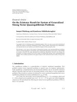
Figure 1: One-line diagram for a typical utility distribution feeder.
components of the feeder lines and loads have a beneficial
impact in preventing catastrophic resonance phenomena
[1, 2]. However, a few other studies on the application of sig-
nal processing techniques to har monic studies have been un-
dertaken on the assumption that harmonic components are
exponentially damped sinusoids. Those techniques include
ESPRIT [6], Prony analysis [4], and system identification
based on the al l-pole (AR) model [7]. These techniques can
help better explain the characteristics of individual harmonic
components. Those techniques need to clear some significant
issues such as intrinsic spurious harmonics that may mislead
the evaluation of the results, the uncertainty of the system
order and the computational burden that prevent real-world
applications. Unfortunately, no work has been extended to
quantify the overall damping of the system.
The organization of this paper is as follows. Section 2 de-
scribes the scope of the problem and develops a smart algo-
rithm for estimating power system damping using capacitor
switching transient data based on Hilbert transform and lin-
ear dynamic system theory in Section 3. Section 4 demon-
strates the efficiency of the proposed technique using data
from an IEEE Test Feeder [8] modeled in the time-domain
power system simulator [9] and actual measurement data in
Section 5. The paper concludes in Section 7.
2. PROBLEM DESCRIPTION AND SCOPE OF
THE PROBLEM
Let us consider a one-line diagram for a power distribution
system in Figure 1, where a shunt capacitor bank is installed
in the distribution feeder and power quality monitoring de-
vices are located on both sides of the capacitor bank. When
the capacitor bank is energized, an oscillatory transient can
be observed in the voltage and current waveforms captured
by the power quality monitors. The oscillation frequency is
indeed the new natural power system resonant frequency
formed by the equivalent inductance and the capacitance of
the switched capacitor bank.
The problem addressed in this paper can be stated as
follows: given voltage waveforms as a result of capacitor
energizing , determine the effective X/R ratio for the reso-
nant frequency at the particular bus of interest. The pro-
posed method makes use of the transient portion of capacitor
switching waveforms captured anywhere in the system. Thus,
the proposed method works well only with capacitors en-
ergized without any mechanism to reduce overvoltage tran-
sients. Therefore, the capacitor banks considered in this work
are those energized with mechanical oil switches. This is rep-
resentative of the banks found in the majority of distribution
feeders.
3. POWER SYSTEM DAMPING ESTIMATION
The estimation of the system damping quantified in terms of
the X/R ratio and the damping ratio ζ requires the use of the
Hilbert transform and the theoretical analysis of the distribu-
tion circuit. The Hilbert transform is used to determine and
extract the circuit properties embedded in the envelope of the
waveshape of the capacitor switching transient waveform. A
brief review of the transform is described in Section 3.1.The
circuit analysis derives and shows the envelope of the tran-
sient waveform which contains the signature of the X/R ratio.
Section 3.2 analyzes the derivation and analysis in detail and
discusses practical consideration.
3.1. Hilbert transform
The Hilbert transform of a real-valued time domain signal
y(t) is another real-valued time domain signal,
y(t), such
that an analytic signal z(t)
= y(t)+jy(t) exists [10]. This
is a generalization of Euler’s formula in the form of the com-
plex analytic signal. It is also defined as a 90-degree phase
shift system as shown below:
y(t) = H
y(t)
=
∞
−∞
y(τ)
π(t − τ)
dτ
= y(t) ∗
1
πt
,
F
y(t)
=
Y( f ) = (− j sgn f )Y( f ),
(1)
where
Y( f ) is the Fourier transform of y(t). From z(t), we
can also write z(t)
= a(t) · e
jθ(t)
,wherea(t) is the envelope
signal of y(t), and θ(t) is the instantaneous phase signal of
y(t).Theenvelopesignalisgivenbya(t)
=
y(t)
2
+ y(t)
2
and the instantaneous phase, θ(t) = tan
−1
(y(t)/y(t)). Using
the property in the second equation of (1), one can easily
obtain the Hilbert transform of a signal, y(t). Let Z( f ) be the
Fourier transform of z(t) and one can obtain the following
Kyeon Hur et al. 3
relations:
Z( f )
= F
z(t)
=
F
y(t)+ j y(t)
=
Y( f )+j
Y( f )
= (1 + sgn f )Y( f )
=
⎧
⎨
⎩
2Y( f )forf>0,
0forf<0,
(2)
z(t)
= F
−1
Z( f )
=
y(t)+ j y(t). (3)
Thus, the inverse Fourier transform of Z( f )givesz(t)as
shown in (3). For the case of quadratic damping, the decay-
ing transient and its Hilbert transform can be represented as
y(t)
= y
m
e
−ζω
n
t
cos
ω
d
t + φ
,
y(t) = y
m
e
−ζω
n
t
sin
ω
d
t + φ
.
(4)
Thus, the resulting envelope, a(t), becomes y
m
e
−ζω
n
t
,where
y
m
is an arbitrary constant magnitude. This is a unique prop-
erty of the Hilbert transform applicable to envelope detec-
tion.
3.2. Algorithm development
3.2.1. Analysis of the distribution system and
definition of the effective X/R ratio
Let us assume that the distribution system is balanced. There-
fore, the Thevenin equivalent source impedance is repre-
sented with R
s
and L
s
, while the line impedance for seg-
ments d
1
and d
2
are represented with its positive sequence
impedance (r + jωL
u
)d
1
= R
1
+ jωL
1
and (r + jωL
u
)d
2
=
R
2
+ jωL
2
,wherer and L
u
are the line resistance and induc-
tance in per unit length. The load impedance is represented
with Z
L
= R
L
+ jX
L
. Let voltage v
s
(t), i
1
(t)andv
L
(t), i
2
(t)be
the instantaneous voltages and currents measured by PQM
1 and PQM 2, respectively, and let v
M
(t) be the voltage over
the capacitor bank.
Thus, one can set up the following differential equations
for the equivalent circuit immediately following the energiza-
tion of the capacitor bank, that is, t
= 0
+
. Note that currents
i
1
and i
2
are measured by PQM 1 and 2 in the direction of the
prevailing system loads as denoted in Figure 1. In the vector-
matrix form, the state equations and observation equations
are expressed as
˙
x(t)
= Ax(t)+Bu(t),
y(t)
= Cx(t),
(5)
where
x(t)
=
di
1
dt
di
2
dt
dv
M
dt
T
,
A
=
⎡
⎢
⎢
⎢
⎢
⎢
⎢
⎢
⎢
⎢
⎣
−
R
s
+ R
1
L
s
+ L
1
0
−1
L
s
+ L
1
0
−
R
2
+ R
L
L
2
+ L
L
1
L
2
+ L
L
1
C
−1
C
0
⎤
⎥
⎥
⎥
⎥
⎥
⎥
⎥
⎥
⎥
⎦
,
B
=
⎡
⎢
⎣
1
0
0
⎤
⎥
⎦
, C = I
3
,(6)
and y(t) is the output vector, x(t) the state vector, and u(t)
the input vector. The input vector, u(t), of this system com-
prises only the equivalent voltage source. The state vector is
regarded as the output vector. Thus, matrix C is a 3
× 3iden-
tity matrix. Let the transfer function G(s), which describes
the behavior between the input and output vectors, be ex-
pressed in the following form [11]:
G(s) = C(sI − A)
−1
B =
G
1
(s), G
2
(s), G
3
(s)
T
,(7)
where
G
1
(s) =
C
L
2
+ L
L
s
2
+
R
L
+ R
2
Cs +1
Δ
,
G
2
(s) =
1
Δ
,
G
3
(s) =
L
2
+ L
L
s +
R
2
+ R
L
Δ
,
(8)
and Δ is a characteristic equation of the system and is repre-
sented as follows:
Δ
=|sI − A|
=
L
s
+ L
1
L
2
+ L
L
Cs
3
+
L
s
+ L
1
R
2
+ R
L
+
L
2
+ L
L
R
s
+ R
1
Cs
2
+
R
s
+ R
1
R
2
+ R
L
C +
L
s
+ L
1
+ L
2
+ L
L
s
+ R
s
+ R
1
+ R
2
+ R
L
.
(9)
The s-domain representation of voltages at PQM 1(V
S
(s)),
PQM 2(V
L
(s)) and across capacitor (V
M
(s)) can be obtained
as follows:
V
S
(s) = V
sc
(s)
G
1
(s)
R
1
+ sL
1
+ G
3
(s)
,
V
L
(s) = V
sc
(s)G
2
(s)
L
L
s + R
L
,
V
M
(s) = V
sc
(s)G
3
(s).
(10)
Since the power system fundamental frequency is sub-
stantially lower than a typical capacitor switching frequency
[12], the input source voltage is considered constant in s-
domain,
V
sc
(s) =
v
sc
t
−
s
s
, (11)
4 EURASIP Journal on Advances in Signal Processing
where v
sc
(t
−
s
) indicates a voltage level immediately before
switching. Note that the roots of the characteristic equation
are the eigenvalues of the matrix A, and the order of the char-
acteristic equation is three. In linear dynamic system the-
ory, the characteristic equation of the second-order proto-
type system is generally considered, that is,
Δ(s)
= s
2
+2ζω
n
s + ω
2
n
, (12)
where ω
n
and ζ are the resonant frequency and the system
damping ratio, respectively. The series RLC circuit is one of
the representative second-order prototype systems, which is
the case of an isolated capacitor bank. Neglecting the circuit
downstream from the capacitor bank, one can obtain the fol-
lowing characteristic equation:
Δ(s)
= s
2
+
R
s
+ R
1
L
s
+ L
1
s +
1
L
s
+ L
1
C
. (13)
Thus, we obtain the following relations:
ω
2
n
=
1
L
s
+ L
1
C
,2ζω
n
=
R
s
+ R
1
L
s
+ L
1
. (14)
From (14), we obtain the damping ratio of the system:
ζ
=
1
2ω
n
R
s
+ R
1
L
s
+ L
1
. (15)
In fact, (15) derives the conventional X/R ratio of the system
at the resonant frequency, which frequently appears in power
system literature to describe the system resonance, that is, the
so-called quality factor, Q,
X
R
=
1
2ζ
= ω
n
L
s
+ L
1
R
s
+ R
1
. (16)
Note that the behavior of the transient voltage measured in
the utility system after energizing the capacitor bank can be
described by the general exponential function in the same
form as (4). Hence, transient voltage can be described as fol-
lows:
v(t)
= v(0)e
−ζω
n
t
p cos
ω
d
t
+ q sin
ω
d
t
=
re
−ζω
n
t
cos
ω
d
t + φ
=
a(t)cos
ω
d
t + φ
,
(17)
where v(0) is an initial condition, ω
d
= ω
n
(1 − ζ
2
) is the
damped resonant frequency, p and q are arbitrary constants,
r
=
p
2
+ q
2
and φ =−tan
−1
(q/p). Keep in mind that the
aforementioned equations are based on the series RLC cir-
cuit without considering loads. Thus, the X/R ratio does not
include damping contributions of the loads and the down-
stream lines to the whole system.
We should emphasize that the damping ratio is not
strictly defined in the higher order system. However, thor-
ough numerical analyses prove that the characteristic equa-
tion in (9) can be reasonably represented by a pair of complex
conjugate dominant poles and one insignificant pole that is
further away from jω axis in the left half s-domain than those
of dominant poles. Therefore, its effec t on transient response
is negligible, which corresponds to the fast-decaying time re-
sponse. Application of the model reduction method [13]to
the voltages of interest also confirms that the transfer func-
tions of V
s
(s)andV
L
(s)in(10) can be reduced, and the trans-
fer function of V
M
(s)in(10) can be approximated after trun-
cating the fast mode as follows:
V
S
(s) ≈ V
sc
(s)
Q
s
2
+2ζ
1
ω
n1
s + ω
2
n1
s
2
+2ζ
2
ω
n2
s + ω
2
n2
,
V
M
(s) ≈ V
sc
(s)
−
Ks+ P
s
2
+2ζω
n
s + ω
2
n
,
(18)
where Q, K,andP are arbitrary constants. V
L
(s)canbere-
duced to the same form as V
S
(s). Note that the damping
term of the reduced second-order system is a function of line
parameters and loads. Thus, it should not be interpreted as
the conventional X/R ratio which is a function only of up-
stream lines and source parameters as defined in (16). How-
ever, the approximate damping term can indicate the relative
X/R ratio of the whole system effectively and can quantify
the overall contributions to the system damping by both lines
and loads. Thus, the paper defines 1/(2ζ) from the reduced
second-order characteristic equation as the effective X/R ra-
tio of the system. What is worthnoting is that the character-
istic equation can vary according to the load composition.
Hence, the X/R ratio is not a unique function of the param-
eters of the lines and loads but depends on the load compo-
sition and line configuration. Note that a parallel representa-
tion of the load elements results in a fourth-order character-
istic equation. However, the fourth-order system can also be
reduced to the second-order prototype system by the model
reduction technique with much bigger damping ratio than
that from the series load representation even under the same
loading condition. This is briefly illustrated in Section 4,but
the details are beyond the scope of the paper. Therefore, the
transient response of the whole system can be described by
(17) as well. This is the motivation for detecting the envelope
of the transient voltage by means of Hilbert transform. Con-
sequently, the exponent,
−ζω
n
,of(17) can lead to the effec-
tive X/R ratio or 1/(2ζ)ifω
n
is available. Since the aforemen-
tioned system parameters for determining the system damp-
ing level are not readily available, we propose an empir ical
method using conventional PQ data for evaluating the effec-
tive X/R ratio. The following section discusses how to obtain
the effective X/R ratio of the system using conventional ca-
pacitor switching transient data.
3.2.2. Implementation and practical consideration
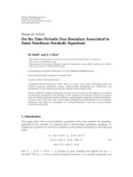
The implementation of the proposed damping estimation
technique is illustrated in Figure 2. The implementation be-
gins with an existing PQ database or a real-time PQ data
stream as used in web-based monitoring devices. Since typi-
cal PQ monitors capture a wide range of disturbance events, a
separate algorithm is needed to distinguish capacitor switch-
ing event data from other PQ data. The identification of ca-
pacitor switching transient waveforms can be done visually
Kyeon Hur et al. 5
PQ data and
system
information
Capacitor switching
identification
- Switching instant
-Numberofsamples
- Sampling rate
Empirical identification of the
free response of the capacitor
bank energizing
Quantification of the
system damping
- Compute the damping ratio using the
relationship between the slope and the
resonant frequency
- Quantify the system damping (X/R
ratio) based on the second-order
prototype system
Hilbert transform analysis
-ApplytheHilberttransform
analysis to the free response signal
- Obtain the envelope data, a(t),
and its logarithm
- Perform linear regression and
estimate the slope parameter, ζω
n
Spectral analysis
- Perform FFT on the
free response signal and
obtain dominant system
resonant frequency
Hilbert damping analysis
Figure 2: Data flow and process diagram of the system damping estimation.
or automatically [7, 14]. Once a single event of capacitor
switching transient data, that is, three-phase voltage, is iden-
tified, we extract transient portions of voltage waveforms af-
ter switching and construct extrapolated voltage waveforms
based on the steady state waveforms after capacitor energiz-
ing. This extrapolation can be done by concatenating a single
period of waveforms captured 3 or 4 cycles after the switching
operation on the assumption that voltage signals are consid-
ered to be (quasi-)stationary for that short period of time. If
the number of samples after the detected switching instant
is not sufficient to form a single period, steady-state voltage
data before capacitor switching can be used alternatively. It is
not uncommon to observe this situation since most of the PQ
monitors store six cycles of data based on the uncertain trig-
gering instant. Wavelet transform techniques, among others,
are most frequently used for effectively determining the exact
switching instant [14]. For example, there exists a commer-
cial power quality monitoring system equipped w ith singu-
larity (switching) detection based on the wavelet transform.
In this effort, we assume that switching time instant can
be accurately detected. Then, we subtract the second from
the first and get the differential portions that are free from
the harmonics already inherent in the system and the volt-
age rise due to reactive energy compensation. This differen-
tial portion can be interpreted as the zero-input (free) re-
sponse of the system, whose behavior is dictated by the char-
acteristic equation as discussed in Section 3.2.1. The process
of deriving this empirical-free response of the capacitor bank
energizing is more detailed in [15]. The Hilbert transform is
then performed to find the envelope signal, a(t), of (17). In
fact, the envelope from the Hilbert transform is not an ideal
exponential function and is full of transients especial ly for
those low-magnitude portions of the signal approaching the
steady-state value (ideally zero). Thus, only a small number
of data are utilized in order to depict the exponential satis-
factorily: one cycle of data from the capacitor switching in-
stant is generally sufficient to produce a good exponential
shape. The number of data will depend on the sampling rate
of the PQ monitoring devices and should be calibrated by
investigating the general load condition, especially when the
method is applied to a new power system in order to opti-
mize the performance. The obtained data is now fitted into
an exponential f unction. The direct way to fit the data into
the exponential function is possible through iteration-based
nonlinear optimization technique. However, the exponential
function is namely an intrinsic linear function, such that the
ln a(t) produces a linear function, that is,
ln
a(t)
=
ln r − ζω
n
t. (19)
As a result, we can apply standard least squares method to
approximate the optimal parameters more efficiently [16].
The solution is not optimal in minimizing the squared er-
ror measure, due to the logarithmic transformation. How-
ever, except for very high damping cases, this transformation
plus the least squares estimation method, creates a very accu-
rate estimate of a(t). The FFTs of the differential voltages may
also provide good spectr al information of the system since
the FFTs are performed on the data virtually free from inher-
ent harmonic components that may produce spurious reso-
nant frequency components [15]. Thus, one can obtain the
effective X/R ratio that quantifies the system damping level,
including impacts from lines and loads. The proposed algo-
rithm is very practical and ready to be implemented in mod-
ern PQ monitoring systems since the conventional capacitor
switching transient data is all it needs and the method is not
computationally intensive.
4. METHOD VALIDATION USING IEEE TEST MODEL
This section demonstrates the application of the damping
estimation method using the IEEE power distribution test
feeder [8]. The test system is a 12.47 kV radial distribution
system served by a 12 MVA 115/12.47 kV delta-Yg trans-
former. The Thevenin equivalent impedance is largely due to
the transformer leakage impedance, that is, Z(%)
= (1+ j10)
on a 12 MVA base. Thus, the equivalent source inductance L
s
would be 3.4372 mH. The evaluation of distance estimates is
carried out under both unbalanced [Z
012
]
UB
(Ω/mi)andbal-
anced [Z
012
]
B
(Ω/mi). Their sequence impedance matrices in
6 EURASIP Journal on Advances in Signal Processing
BUS 1 Line
BUS 2
Line 1 Line 2
Constant P, Q load
BUS 2LV
Monitor 1 Monitor 2
Distributed loads
Constant
impedance load
Substation
115 kV/12.47 kV
12 MVA
Z
= 1+ j10(%)
350 kVar
12.47/0.48 kV
1MVA
Z
= 1+ j5(%)
Figure 3: IEEE distribution system test case with modification and additional capacitor bank.
Ohms per mile are as follows, respectively:
Z
012
UB
=
⎡
⎢
⎢
⎢
⎣
0.7737 + j1.9078 0.0072 − j0.0100 −0.0123 − j0.0012
−0.0123 − j0.0012 0.3061 + j0.6334 −0.0488 + j0.0281
0.0072
− j0.0100 0.0487 + j0.0283 0.3061 + j0.6334
⎤
⎥
⎥
⎥
⎦
,
Z
012
B
=
⎡
⎢
⎢
⎢
⎣
0.7737 + j1.9078 0 0
00.3061 + j0.6333 0
000.3061 + j0.6334
⎤
⎥
⎥
⎥
⎦
.
(20)
The positive sequence line inductance per mile, L
u
,forboth
balanced and unbalanced feeders is 1.6801 mH/mi. The ef-
ficacy of the proposed technique is evaluated under the fol-
lowing conditions: (a) ignore loads and circuits downstream
from the switched capacitor bank when all lines are assumed
balanced, (b) include loads and circuits downstream from
the bank and vary the loading conditions when the loads
and lines are assumed balanced, and investigate the feasibil-
ity of the proposed method when harmonic currents are in-
jected from the nonlinear loads and resonance occurs as well,
and (c) evaluate the same system as in (b), however, loads
and lines are unbalanced. Loads illustrated in Figure 3 are
modeled as a combination of fixed impedance and dominant
complex constant power loads which are appropriately mod-
eled as variable R and L in parallel. They are connected at the
12.47 kV as well as at the 0.48 kV level through a 1 MVA ser-
vice transformer Z(%)
= (1 + j5). A 350 kVar three phase
switched capacitor bank is located d
1
miles out on the feeder.
Two PQ monitors are installed both at the BUS 1 (substation)
and BUS 2. Note that the conventional sampling rate of 256
samples/cycle is applied in the following studies.
Table 1: Estimation results for case (a) with d
1
= 3 miles.
Parameters f
res
= ω
d
/2πζ X/R
Analytical results 707.36 0.0139 35.96
Estimates
706.42 0.0135 37.05
4.1. Evaluation cases with downstream loads and
circuits omitted
The damping estimation technique is evaluated for a bal-
anced feeder, and loads and circuits downstream from the
capacitor bank are excluded from the simulation model. The
estimated parameters are compared with the analytical re-
sults derived from the characteristic equation in (9)andsum-
marized in Tab le 1 (for d
1
= 3miles).
The above results show that the proposed techniques
provide reasonably accurate estimates of resonant frequency,
damping ratio, and effective X/R ratio. Note that the resonant
frequency in the resulting table indicates a damped resonant
frequency, which is the frequency obtainable from the mea-
surement data. However, the damped resonant frequency is
very close to the natural resonant frequency since in general
the damping ratio is very small. It should also be noted that
the fractional numbers are not included to indicate the high
accuracy of the estimates but to present the same significant
figures as those of the analytical values. The frequency in-
terval, Δ f , between two closely spaced FFT spectral lines is
15.03 Hz based on the number of samples (1024) and sam-
pling rate of the PQ data (256 samples per cycle).
4.2. Evaluation cases for balanced lines and
balanced loads
4.2.1. Linear load
In this case, three phase balanced lines and loads downstream
from the capacitor bank are included. The lines are config-
ured as d
1
= 3milesandd
2
= 1 mile. Note that loads are
modeled with series R and L in an aggregate manner and
Kyeon Hur et al. 7
−15
−10
−5
0
5
10
15
kV
0.14 0.15 0.16 0.17 0.18
Time (s)
Measured data
Extrapolated data
(a)
−4
−3
−2
−1
0
1
2
3
4
kV
0.14 0.15 0.16 0.17 0.18
Time (s)
Envelope from Hilbert transform
Transient data (measured data-extrapolated data)
(b)
−1.5
−1
−0.5
0
0.5
1
1.5
Ln a(t)
0.135 0.14 0.145
Time (s)
Linear model for log a(t)
(c)
−4
−3
−2
−1
0
1
2
3
4
kV
0.14 0.15 0.16 0.17 0.18
Time (s)
Reconstructed exp function
(d)
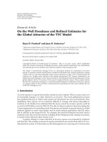
Figure 4: Step-by-step procedures of the proposed damping estimation method. (a) Extracting the transient voltage differential between the
measured data (bold) and the extrapolated data (solid), (b) detecting envelope by way of Hilbert transform, (c) performing linear regression
for the natural logarithms of the envelope, which results in the effective X/R ratio, and (d) reconstructing exponential function that perfectly
fits in the voltage transient response.
Table 2: Estimation results when load power factor is 0.95.
Loading
condition
Moderate, 3.16 MVA Heavy, 7.37 MVA
Parameters
f
res
=
ζX/R
f
res
=
ζX/R
ω
d
/2π ω
d
/2π
Analytical
results
772.28 0.0293 17.08 845.97 0.0387 12.92
Estimates 766.55 0.0286 17.47 841.70 0.0373 13.38
connected to BUS 2. The proposed technique is applied to
quantify the system damping level for varying load sizes and
power factors. The resulting parameters are compared with
Table 3: Estimation results when load power factor is 0.90.
Loading
condition
Moderate, 3.16 MVA Heavy, 7.37 MVA
Parameters
f
res
=
ζX/R
f
res
=
ζX/R
ω
d
/2π ω
d
/2π
Analytical
results
758.51 0.0217 23.00 818.11 0.0273 18.31
Estimates 751.52 0.0214 23.38 811.64 0.0266 18.80
the analytical results using the characteristic equation in (18)
andsummarizedinTables2–4. The results demonstrate that
the proposed technique can provide very accurate estimates
8 EURASIP Journal on Advances in Signal Processing
Table 4: Estimation results when load power factor is 0.87.
Loading
condition
Moderate, 3.16 MVA Heavy, 7.37 MVA
Parameters
f
res
=
ζX/R
f
res
=
ζX/R
ω
d
/2π ω
d
/2π
Analytical
results
754.58 0.0198 25.23 810.24 0.0242 20.69
Estimates 751.52 0.0194 25.74 811.64 0.0234 21.38
of resonant frequency, damping ratio, and effective X/R ra-
tio. It is also observed that the overall system damping le vel
is more affected by the power fac tor of the load than the
load size. The effective X/R ratio of a moderate load w ith
0.95 pf is even less than that of heavy load with 0.90 pf. Note
the change in resonant frequency according to the load con-
dition. The following (21) describes an example of system
model reduction process for a moderate loading condition
with 0.95 pf. The rapid mode truncation reduces the order
of transfer function from (10)to(18). The resulting charac-
teristic equation is presented in (22) by taking appropriate
numeric values for line parameters according to the positive
sequence equivalent circuit;
V
S
(s)
V
sc
(s)
=
1.278s
3
+1.495e3s
2
+4.778e7s +48.02e9
2.15s
3
+2.65e3s
2
+5.125e7s +48.15e9
=⇒
0.59455
s
2
+ 132.6s +3.732e7
s
2
+ 284.2s +2.357e7
,
(21)
Δ(s)
= s
2
+ 284.2s +2.357e7. (22)
Note that transient voltage response in any monitoring loca-
tion in the power system of interest is governed by the same
characteristic equation. In fact, the estimates and the theo-
retical results for the system damping level at PQM 1, 2 and
over capacitor location are identical. Figure 4 illustrates the
damping estimation procedures. The steps can be summa-
rized as: (a) detecting the capacitor switching time instant;
(b) selecting a single cycle of steady state PQ data by extract-
ing a cycle of data after passing one or two cycles from the
switching instant, or a single cyclic data right before the ca-
pacitor bank energizing when there is insufficient data after
the switching event; (c) this extracted single cycle can be con-
catenated to form a virtual steady-state data based on our as-
sumption that the data is stationary; (d) computing the one
cycle difference between the actually measured data and the
virtual steady-state data from the switching instant. This re-
sults in the empirical-free response of the capacitor bank en-
ergizing or the pure transient voltage portion. The damped
resonant frequency is accurately determined using the paral-
lel resonant frequency estimation method addressed in [15].
4.2.2. Nonlinear load
In this situation, Tab le 5 presents the estimation results when
harmonic currents are injected from the nonlinear loads.
0
10
20
30
40
50
60
70
80
90
Z (ohm)
0 100 200 300 400 500 600 700 800 900 1000
Frequency (Hz)
No load
Light load
Heavy load
Figure 5: System impedance scan results of a typical 12.47 kV sys-
tem for two d ifferent loading conditions.
The load model with power factor of 0.87 is modified to in-
ject the fifth and seventh harmonic currents by 3% of the
60 Hz component and the capacitor bank size is increased to
850 kVar to support the resonance condition near the seventh
harmonic. The distribution feeder is balanced with d
1
= 4
miles and d
2
= 1 mile. Both moderate and heavy loading
conditions with the same power factor are investigated. The
impedance scan results and the voltage and current wave-
forms are illustrated in Figures 5 and 6 to emphasize the load
impact on the system damping and resonant frequency. The
change from a heavy to a moderate loa d condition causes
a system resonance phenomenon due to the new resonant
frequency formed near at the seventh harmonic as well as
the increased peak impedance level. Thus, injecting the same
amount of harmonic currents can result in different levels of
distorted voltage and current waveforms. However, it is often
neglected that change in the load condition shifts the reso-
nant frequency. This can be more influential in mitigating
the resonance phenomena in many cases than lowered peak
impedance level. The estimation results presented in Table 5
demonstrate that the performance of the proposed technique
is independent of the load type, that is, whether it is linear or
nonlinear, as long as the steady-state voltage waveforms are
considered to be (quasi)-stationary during the observation
period immediately after the capacitor bank operation. The
estimated parameters are very close to those theoretical val-
ues calculated from a positive-sequence equivalent circuit as
well.
4.3. Evaluation case for unbalanced lines and loads
In this case, the system is modeled with unbalanced lines and
loads with d
1
= 3milesandd
2
= 2 miles. The resulting
Kyeon Hur et al. 9
−15
−10
−5
0
5
10
15
kV
0.10.12 0.14 0.16 0.18 0.2
Time (s)
(a)
−0.6
−0.4
−0.2
0
0.2
0.4
0.6
0.8
kA
0.10.12 0.14 0.16 0.18 0.2
Time (s)
(b)
−15
−10
−5
0
5
10
15
kV
0.10.12 0.14 0.16 0.18 0.2
Time (s)
(c)
−0.4
−0.2
0
0.2
0.4
0.6
kA
0.10.12 0.14 0.16 0.18 0.2
Time (s)
(d)
Figure 6: Voltage and current waveforms at a simulated 12.47 kV substation: (a), (b) voltage and current for a system under heavy loading
condition and (c), (d) voltage and current when resonance occurs due to loading condition change.
voltage unbalance is 0.5%. Note that only a moderate load
size is considered in this case C, since the dominant com-
plex constant power load is modeled by a combination of
RL in parallel. The damping from the load then becomes
significantly higher compared to that from the combination
of RL in series which are employed in the case B. Although
the lines and loads are unbalanced, the positive sequence
equivalent circuit is analyzed to provide approximate the-
oretical values using three-phase active and reactive power
measured at the substation
− 2.91 MVA, 0.92 lagging pf. Al-
though the estimates from each phase show slight deviations,
it should be judged that the results are reasonably accurate
since they are in the region of expected theoretical values as
presented in Tabl e 6. It is also observed that the method is
independent of the load composition since only the wave-
form data is needed. As illustrated in Figure 7, the voltage
transient is much shorter than that of the balanced line case.
Thus, care must be taken to select the observation period
to guarantee the optimal envelope from Hilbert t ransform:
empirical study recommends less than a half-cycle data for
this high damping case. Note that the effective X/R ratio is
in the order of 1 or 2. The X/R ratio is approximately 5%
of the isolated capacitor bank case, which has been conven-
tionally employed for harmonic studies. Therefore, thorough
understanding of the load type, composition, and condition
is required in advance to perform any mitigation measures
against harmonic issues and the proposed technique pro-
vides system impedance characteristic in a very practical but
precise manner.
5. METHOD APPLICATION USING ACTUAL
MEASUREMENT DATA
The performance of the damping estimation technique is
also validated using actual data of a capacitor switching tran-
sient event. The transient event was captured using a widely
10 EURASIP Journal on Advances in Signal Processing
Table 5: Estimation results for nonlinear load.
Loading
condition
Moderate, 3.16 MVA Heavy, 7.37 MVA
Parameters
f
res
=
ζX/R
f
res
=
ζX/R
ω
d
/2π ω
d
/2π
Analytical
results
439.58 0.0374 13.38 476.94 0.0454 11.02
Estimates 439.27 0.0370 13.50 476.45 0.0437 11.43
Table 6: Estimation results with unbalanced lines and loads.
Phase A Phase B Phase C
Theoretical
value
f
res
= ω
d
/2π 766.55 766.55 766.55 762.30
ζ
0.2918 0.2097 0.3732 0.3459
X/R
1.713 2.356 1.340 1.446
available power quality monitoring device at a 115 kV sub-
station of a utility company. Figure 8 illustrates the measured
voltage waveforms and the results from the Hilbert damping
analysis while Tabl e 7 summarizes the resulting estimated pa-
rameters. As shown in Figure 8(d), there are two prominent
frequency components at 526 Hz and 721 Hz. However, the
lower component at 526 Hz is selected to estimate the effec-
tive X/R ratio since the magnitude at 526 Hz is much bigger.
Although there are no theoretical values to evaluate the esti-
mation results, the obtained values are considered to be rea-
sonable in that the system is at a subtransmission level whose
X/R ratio is generally known to be in the order of 30, and
the envelope nicely matches the transient voltage as shown
in Figure 8(c).
6. DISCUSSIONS
As indicated in the application to the real data, however, the
Hilbert damping analysis may cause considerable estimation
errors for the following possible two scenarios: (1) the PQ
data is significantly corrupted by noises such that the station-
arity assumption on the PQ data is no longer valid; (2) the
extracted free response possess multiple comparable reso-
nant frequency components such that there is no single dom-
inant mode. One may consider the following ways around
these problems.
(i) Reinforce the signal preprocessing stages by adding
the high frequency noise rejection filters and adding the
bandpass filters. Thus, one can appropriately select impor-
tant resonant frequencies based on the system studies fol-
lowed by the Hilbert damping analysis.
(ii) Exploit the wavelet transform which inherently em-
beds the bandpass filtering which can provide a unified al-
gorithm to estimate the damping ratios of those multiple
−4
−3
−2
−1
0
1
2
3
4
5
kV
0.131 0.132 0.133 0.134 0.135 0.136 0.137 0.138 0.139 0.14
Time (s)
Envelope from Hilbret transform
Identified decreasing exponential function
Transient data
Figure 7: Hilbert damping analysis of phase A transient voltage of
amoderatelyloadedsystem.
Table 7: Estimation results for actual data.
Parameters Estimates
f
res
= ω
d
/2π 526
ζ
0.0154
X/R
32.50
modes. We will provide this wavelet-based power system
damping estimation algorithm in the near future.
(iii) Apply methodology known to be robust to ambient
noise signals such as ESPRIT which includes the noise term
in its original mathematical model. Thus, one can even ex-
tract important system information even from the heavily
distorted data at the cost of increased computational burden
[7].
7. CONCLUSIONS
This paper proposed a novel method to estimate utility dis-
tribution system damping. The proposed method is derived
using linear dynamic system theory and utilizes the Hilbert
system damping analysis to extract circuit signatures describ-
ing the system damping embedded in the voltage waveforms.
The efficacy of the integrated signal processing and system
theory was demonstrated using data obtained from simula-
tions of a representative utility distribution system and an
actual power system. The results show that the proposed
method can accurately predict the utility distribution system
damping parameters. Limitations of the proposed method
are discussed with possible solutions suggested.
Kyeon Hur et al. 11
−150
−100
−50
0
50
100
150
kV
00.02 0.04 0.06 0.08 0.1
Time (s)
(a)
kV
0.03 0.035 0.04 0.045 0.05 0.055 0.06
Time (s)
Va
Extrapolated data
(b)
kV
0.03 0.035 0.04 0.045 0.05 0.055 0.06
Time (s)
Positive envelope from Hilbert transform
Volta g e d ifferential
(c)
FFT of differential voltages
0 200 400 600 800 1000
Frequency (Hz)
Va
Vc
(d)
Figure 8: Application of the damping estimation method to actual data: (a) voltage waveform of phase A (bold) and C, (b) Phase A voltage
transient and the extrapolated voltage after capacitor switching, (c) positive and negative envelope of voltage A detected by Hilbert damping
analysis, (d) spectral information of the differential voltage A and C.
REFERENCES
[1] R.D.Dugan,M.F.McGranaghan,S.Santoso,andW.H.Beaty,
Electrical Power Systems Quality, McGraw-Hill, New York, NY,
USA, 2nd edition, 2003.
[2] T. E. Grebe, “Application of distribution system capacitor
banks and their impact on power quality,” IEEE Transactions
on Industry Applications, vol. 32, no. 3, pp. 714–719, 1996.
[3] M. Banejad and G. Ledwich, “Quantification of damping con-
tribution from loads,” IEE Proceedings: Generation, Transmis-
sion and Distribution, vol. 152, no. 3, pp. 429–434, 2005.
[4] J. F. Hauer, “Application of Prony analysis to the determination
of modal content and equivalent models for measured power
system response,” IEEE Transactions on Power Systems, vol. 6,
no. 3, pp. 1062–1068, 1991.
[5] P. Kundur, PowerSystemStabilityandControl, EPRI, Palo Alto,
Calif, USA, 1994.
[6] M.H.J.Bollen,E.Styvaktakis,andI.Y.H.Gu,“Categorization
and analysis of power system transients,” IEEE Transactions on
Power Delivery, vol. 20, no. 3, pp. 2298–2306, 2005.
[7] I. Y. H. Gu and E. Styvaktakis, “Bridge the gap: signal pro-
cessing for power quality applications,” Electric Power Systems
Research, vol. 66, no. 1, pp. 83–96, 2003.
[8] PES Distribution Systems Analysis Subcommittee, Radial Test
Feeders. IEEE, />html.
12 EURASIP Journal on Advances in Signal Processing
[9] Manitoba HVDC Research Centre, Winnipeg, Canada.
PSCAD/EMTDC version 4.2.
[10] J. S. Bendat and A. G. Piersol, Random Data: Analysis and Mea-
surement Procedures, John Wiley & Sons, New York, NY, USA,
1986.
[11] B. C. Kuo and F. Golnaraghi, Automatic Control Systems,John
Wiley & S ons, New York, NY, USA, 8th edition, 2003.
[12] A. Greenwood, Electrical Transients in Power Syste ms ,JohnWi-
ley & Sons, New York, NY, USA, 2nd edition, 1991.
[13] A. C. Antoulas, Approximation of Large-Scale Dynamical Sys-
tems, SIAM, Philadelphia, Pa, USA, 2005.
[14]S.Santoso,E.J.Powers,W.M.Grady,andP.Hofmann,
“Power quality assessment via wavelet transform analysis,”
IEEE Transactions on Power Delivery, vol. 11, no. 2, pp. 924–
930, 1996.
[15] K. Hur and S. Santoso, “An improved method to estimate
empirical system parallel resonant frequencies using capacitor
switching transient data,” IEEE Transactions on Power Delivery,
vol. 21, no. 3, pp. 1751–1753, 2006.
[16] L. L. Scharf, StatisticalSignalProcessing:Detection,Estima-
tion and Time-Series Analysis, Addison Wesley, New York, NY,
USA, 1991.
Kyeon Hur received his B.S. and M.S. de-
grees in electr ical engineering from Yon-
sei University, Seoul, Korea, in 1996 and
1998. He was with Samsung Electronics as
an R&D Engineer between 1998 and 2003,
where he designed control algorithms for
electric drives. He is now a Ph.D candidate
in electrical and computer eng ineering at
The University of Texas at Austin. His ar-
eas of interest include power quality, power
electronics, renewable energy, and the application of novel digital
signal processing techniques to nonlinear and/or transient prob-
lems in engineering. He is a recipient of KOSEF (Korea Science and
Engineering Foundation) Graduate Scholarship.
Surya Santoso has been an Assistant Pro-
fessor with Department of Electrical and
Computer Engineering, The University of
Texas at Austin since 2003. He was a Se-
nior Power Systems/Consulting Engineer
with Electrotek Concepts, Knoxville, TN
between 1997 and 2003. He holds the BSEE
degree from Satya Wacana Christian Uni-
versity, Indonesia, and the MSEE and Ph.D
degreesfromtheUniversityofTexasat
Austin. His research interests include power system analysis, mod-
eling, and simulation. He is a Coauthor of Electrical Power Sys-
tems Quality published by McGraw-Hill, now in its 2nd edition. He
chairs a task force on intelligent system applications to data mining
and data analysis, and a Member of the IEEE PES Power Systems
Analysis, Computing and Economics Committee.
Irene Y. H. Gu is a Professor in signal pro-
cessing at the D epartment of Signals and
Systems at Chalmers University of Technol-
ogy, Sweden. She received the Ph.D. de-
gree in electrical engineering from Eind-
hoven University of Technology (NL), in
1992. She was a Research Fellow at Philips
Research Institute IPO (NL) and Stafford-
shire University (UK), and a Lecturer at The
University of Birmingham (UK) during 1992–1996. Since 1996, she
has been with Chalmers University of Technology (Sweden). Her
current research interests include signal processing methods with
applications to power disturbance data analysis, signal and image
processing, pattern classification and machine learning. She served
as an Associate Editor for the IEEE Transactions on Systems, Man
and Cybernetics during 2000–2005, the Chair-Elect of Signal Pro-
cessing Chapter in IEEE Swedish Section 2002–2004, and is a Mem-
ber of the Editorial Board for Applied Signal Processing since July
2005. She is the Coauthor of Signal processing of power quality dis-
turbances published by Wiley/IEEE-Press 2006.