Báo cáo hóa học: " Research Article Wideband Impulse Modulation and Receiver Algorithms for Multiuser Power Line Communications" doc
Bạn đang xem bản rút gọn của tài liệu. Xem và tải ngay bản đầy đủ của tài liệu tại đây (1019.99 KB, 14 trang )
Hindawi Publishing Corporation
EURASIP Journal on Advances in Signal Processing
Volume 2007, Article ID 96747, 14 pages
doi:10.1155/2007/96747
Research Article
Wideband Impulse Modulation and Receiver Algorithms for
Multiuser Power Line Communications
Andrea M. Tonello
Dipartimento di Ingegneria Elettrica, Gestionale, e Meccanica (DIEGM), Universit
`
a di Udine, Via delle Scienze 208,
33100 Udine, Italy
Received 8 November 2006; Accepted 23 March 2007
Recommended by Mois
´
es Vidal Ribeiro
We consider a bit-interleaved coded wideband impulse-modulated system for power line communications. Impulse modulation
is combined with direct-sequence code-division multiple access (DS-CDMA) to obtain a form of orthogonal modulation and to
multiplex the users. We focus on the receiver signal processing algorithms and derive a maximum likelihood frequency-domain
detector that takes into account the presence of impulse noise as well as the intercode interference (ICI) and the multiple-access
interference (MAI) that are generated by the frequency-selective power line channel. To reduce complexity, we propose several
simplified frequency-domain receiver algorithms with different complexity and performance. We address the problem of the prac-
tical estimation of the channel frequency response as well as the estimation of the correlation of the ICI-MAI-plus-noise that is
needed in the detection metric. To improve the estimators performance, a simple hard feedback from the channel decoder is also
used. Simulation results show that the scheme provides robust performance as a result of spreading the symbol energy both in
frequency (through the wideband pulse) and in time (through the spreading code and the bit-interleaved convolutional code).
Copyright © 2007 Andrea M. Tonello. This is an open access article distributed under the Creative Commons Attribution License,
which permits unrestricted use, distribution, and reproduction in any medium, provided the original work is properly cited.
1. INTRODUCTION
The design of broadband communication modems for trans-
mission over power lines (PL) is an interesting and open
problem especially with reference to the development of reli-
able transmission and advanced signal processing techniques
that are capable of coping with the harsh properties of the
power line channel and noise [1]. In this paper, we deal
with advanced signal processing algorithms for a wideband
(beyond 20 MHz) impulse-modulated modem [2–4]. Up to
date, impulse modulation has only been considered for ap-
plication in ultra-wideband (UWB) wireless channels [5–7].
It has interesting properties in terms of simple baseband im-
plementation and robustness against channel frequency se-
lectivity and interference. Differently from the wireless con-
text, PL channels have a narrower transmission bandwidth
[8] and are characterized by several background disturbances
as colored and impulse noise [9]. Nevertheless, wideband im-
pulse modulation is an attrac tive scheme for application over
this medium as experimental trials have shown [4]. The basic
idea behind impulse modulation is to convey information by
mapping an information symbol stream into a sequence of
short-dur ation pulses. Pulses (referred to as monocycles) are
followed by a guard time to cope with the channel time dis-
persion. The monocycle can be designed to shape the occu-
pied spectrum and in particular to avoid the low frequencies
where we typically experience higher levels of background
noise. Since our system deploys a fractional bandwidth (ra-
tio between signaling bandwidth and center carrier) larger
than 20%, it can be classified as an ultra wideband system
according to the FCC. We consider indoor applications such
as local area networks, peripheral office connectivit y, and
home/industrial automation. Impulse modulation is an at-
tractive transmission technique also for in-vehicle PLC sys-
tems and for PL pervasive sensor networks where the trans-
mitting nodes need to use a simple modulation scheme. In
general, we assume that a number of nodes (users) wish to
communicate sharing the same PL grid. Communication is
from one node to another node such that if other n odes
simultaneously access the medium, they are seen as poten-
tial interferers. In order to allow for users’ multiplexing, we
deploy direct-sequence code-division multiple access (DS-
CDMA) [6, 10–12]. The user’s information is conveyed us-
ing a certain signature waveform that is a repetition of time-
delayed and weighted monocycles that span a transmission
frame.
2 EURASIP Journal on Advances in Signal Processing
y(t) y(nT
c
) y
k
(nT
c
)
Sampler
S/P
M-point
FTT
FD
detection
De-
interleav er
Viterbi
decoder
FD
parameters
estimation
Encode
and
interleave
Convolutional
encoder
Bit
interleav er
DS-CDMA
impulse
modulation
s
(u)
(t)
PL
channel
+
MAI
Noise
Front-end
filter
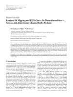
Figure 1: Impulse-modulated PL system wi th frequency-domain receiver processing and iterative decoding.
A key point in the proposed approach is that the sym-
bol energy is spread over a wideband which makes the sys-
tem robust to narrowband interference and capable of ex-
ploiting the channel frequency diversity. Furthermore, this
modulation approach is simple at the transmitter side and re-
quires a baseline correlation receiver that filters the received
signal with a template waveform [2, 7].Thetemplatewave-
form has to be matched to the equivalent impulse response
that comprises the desired user’s waveform and the chan-
nel impulse response. To achieve high perfor mance, this re-
ceiver requires accurate estimation of the channel which can
be complex if performed in the time domain [13, 14]because
of the large time dispersion that is introduced by the wide-
band frequency-selective PL channel. Further, the channel-
frequency selectivity introduces intercode interference (ICI)
(interference among the codes that are assigned to the same
user) and multiple-access interference (MAI) when multiple
users access the network. This translates into performance
losses and suggests some form of multiuser detection or in-
terference cancellation. Therefore, in this paper we focus on
the receiver side and we propose a novel frequency-domain
(FD) detection approach which allows to obtain high per-
formance and to keep the complexity at moderate levels. FD
receivers have recently attracted considerable attention both
for equalization in single carrier systems [15] and in multi-
carrier (OFDM) systems [16, 17]. We have in vestigated FD
processing in a UWB wireless system in [10], and described
preliminary results for the power line scenario in [11, 12].
The contribution of the present paper is about the derivation
of a maximum likelihood joint detector that operates in the
frequency domain in the presence of MAI and impulse noise
(Section 3). The detection metric used in this receiver is con-
ditional on the knowledge of the channel of the desired user
and on the knowledge of the occurrence of the impulse noise.
From this receiver, with certain approximations, we de-
scribe in Section 4 several novel FD algorithms, in particular,
a simplified FD joint detector, an FD iterative detector, and
an FD interference decorrelator. They all include the capabil-
ity of adapting to impulse noise and rejecting the ICI/MAI,
but have different levels of performance and complexity.
We focus on the practical estimation of the parameters
that are needed in the detection algorithms (Section 5). In
particular, we address the FD channel estimation problem,
the estimation of the correlation of the noise and the inter-
ference, and the estimation of the impulse noise occurrence.
Frequency-domain channel estimation for the desired user
is done with a recursive least-squares (RLS) algorithm [18].
Further, channel coding is also considered and it is based
on bit-interleaved convolutional codes. In this case, we show
that iterative processing [19] with simple hard feedback from
the decoder allows to run the parameter estimators in a data
decision-driven mode which betters the overall receiver per-
formance.
Finally, we describe in Section 6 the key features of a PL
impulse-modulated modem that has been used to assess per-
formance and whose hardware prototype is described in [4].
To this respect, we propose the use of a wideband statisti-
cal channel model that allows to evaluate the system perfor-
mance by capturing the ensemble of indoor PL grid topolo-
gies.
2. WIDEBAND SYSTEM MODEL
Weconsiderasystemwhereanumberofnodes(users)com-
municate sharing the same PL network. Communication is
from one node to another, such that if other nodes simul-
taneously access the medium, they are seen as potential in-
terferers. The transmission scheme (Figure 1) uses wideband
impulse modulation combined with DS data spreading [11].
Users’ multiplexing is obtained in a CDMA fashion allocat-
ing the spreading codes among the users.
The signal transmitted by user u can be written as
s
(u)
(t) =
k
i∈C
u
b
(u,i)
k
g
(u,i)
t −kT
f
,(1)
where g
(u,i)
(t) is the waveform (signature code) used to con-
vey the ith information symbol b
(u,i)
k
of user u that is trans-
mitted during the kth frame. Each symbol belongs to the
pulse amplitude modulation (PAM) alphabet [18], and it
Andrea M. Tonello 3
c
(u,i)
0
··· c
(u,i)
L
−1
T
g
T
T
f
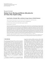
Figure 2: Frame format for user u and code i.
carries log
2
M
S
information bits where M
S
is the number
of PAM levels, for example, with 2-PAM b
(u,i)
k
has alphabet
{−1, 1}. T
f
is the symbol period (frame duration) as shown
in Figure 2. C
u
denotes the set of code indices that are allo-
cated to user u.Thus,useru can adapt its rate by transmitting
|C
u
|=size{C
u
} information symbols per frame.
The signature code (Figure 2) comprises the weighted
repetition of L
≥ 1 narrow pulses (monocycles):
g
(u,i)
(t) =
L−1
m=0
c
(u,i)
m
g
M
(t −mT), (2)
where c
(u,i)
m
∈{−1, 1}are the codeword elements (chips), and
T is the chip period. The monocycle g
M
(t) can be appropri-
ately designed to shape the spec trum occupied by the trans-
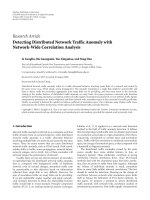
mission system. In this paper we consider the second deriva-
tive of the Gaussian pulse (Figure 3(a)). An interesting prop-
erty is that its spectrum does not occupy the low frequencies
where we experience higher levels of man-made background
noise (Figure 3(b)). Further, the sy mbol energy is spread over
a wideband which makes the system robust to narrowband
interference and capable of exploiting the channel frequency
diversity. Since the attenuation in PL channels increases with
frequency, we limit the transmission bandwidth to about
50 MHz using a pulse with D
= 126 nanoseconds. In typi-
cal system design, we choose the chip period T
≥ D and we
further insert a guard time T
g
between frames to cope with
the channel time dispersion (Figure 2). The frame duration
has, therefore, duration T
f
= LT + T
g
.
2.1. User multiplexing
Users are multiplexed by assig ning distinct codes to distinct
users. In our design, the codes are defined as follows:
c
(u,i)
m
= c
(u)
1,m
c
(i)
2,m
, m = 0, , L − 1, i = 0, , L − 1, (3)
where
{c
(u)
1,m
} is a binary (±1) pseudorandom sequence of
length L allocated to user u, while
{c
(i)
2,m
} is the ith binary
(
±1) Walsh Hadamard sequence of length L [18]. With this
choice, each node can use all L Walsh codes, which yields
a peak data rate per user equal to R
= L/T
f
symb/s. It ap-
proaches log
2
M
S
/T bit/s with long codes. While the signals
of a given user are orthogonal, the ones that belong to dis-
tinct transmitting nodes are not. The random code
{c
(u)
1,m
} is
used to introduce code diversity and to randomize the effect
of the MAI.
2.2. Channel coding
We consider the use of bit-interleaved convolutional codes
(Figure 1)[18]. A block of information bits is coded, inter-
leaved, and then modulated. Interleaving spans a packet of
N frames that we refer to as superframe. This coding ap-
proach yields good performance also in the presence of im-
pulse noise as it will be shown in the following.
2.3. Received signal
The signals that are transmitted by distinct nodes (users)
propagate through distinct channels with impulse response
h
(u)
(t). At the receiver of the desired node, we deploy a band-
pass front-end filter with impulse response g
FE
(t) = g
M
(−t)
that is matched to the transmit monocycle and that sup-
presses out-of-band noise and interference. Then, the output
signal in the presence of N
I
other users (interferers) reads
y(t)
=
k
i∈C
0
b
(0,i)
k
g
(0,i)
EQ
t −kT
f
+ I(t)+η(t)
I(t)
=
k
N
I
u=1
i∈C
u
b
(u,i)
k
g
(u,i)
EQ
t −kT
f
− Δ
u
,
(4)
where the equivalent impulse response for user u and sym-
bol i (equivalent signature code) is denoted as g
(u,i)
EQ
(t) =
g
(u,i)
∗h
(u)
∗g
FE
(t). It comprises the convolution of the signa-
ture code of indices (u, i) with the channel impulse response
of the corresponding user, and the front-end filter. The in-
dex u
= 0 denotes the desired user. Δ
u
denotes the time de-
lay of user u with respect to the desired user’s frame timing .
I(t) is the MAI term, while η(t) denotes the additive noise.
The users experience distinct channels that introduce identi-
cal maximum time dispersion.
2.4. Noise models
In this paper, we consider the presence of background col-
ored and impulse noise [9]. Several impulse noise models
have been proposed in the literature. For instance, the class
A-B Middleton and the two-term Gaussian models [20, 21]
have been used to characterize the probability density func-
tion (pdf) of the impulse noise. The temporal characteristics
of asynchronous (to the main cycle) impulse noise have been
modeled via Markov chains [9], or using a simple modifi-
cation of the two-term mixture model which assumes that
when a spike occurs, it lasts for a given amount of time [22].
In the receiver algorithms that we describe, differently from
other approaches, we do not use optimal metrics that are
based on the assumption of a stationary white noise pro-
cess with a given pdf, for example, [23, 24]. In our approach
4 EURASIP Journal on Advances in Signal Processing
0 30 60 90 120
t (ns)
−0.5
0
0.5
1
g(t)
(a)
01020304050
f (MHz)
−50
−40
−30
−20
−10
0
|G( f )| (dB)
(b)
Figure 3: (a) Monocycle impulse response, g
M
(t) ∼ (1 −π((t − D/2)/T
0
)
2
)exp(−π/2((t − D/2)/T
0
)
2
), where D ≈ 5.23T
0
is the monocycle
duration. (b) Monocycle frequency response.
(see Section 3), the receiver adapts to the impulse noise oc-
currence and treats it as a nonstationary colored Gaussian
process. To do so, as it will be explained, we need to estimate
the impulse noise occurrence and its locally stationary corre-
lation.
2.5. Statistical channel model
The frequency-selective PL channel is often modelled accord-
ing to [8], that is, we synthesize the bandpass frequency re-
sponse with N
P
multipaths as
H
+
( f ) =
N
P
p=1
g
p
e
−j(2πd
p
/v) f
e
−(α
0
+α
1
f
K
)d
p
,0≤ B
1
≤ f ≤ B
2
,
(5)
where
|g
p
|≤1 is the transmission/reflection factor for path
p, d
p
is the length of the path, v = c/
√
ε
r
with c speed of light,
and ε
r
, dielectric constant. The parameters α
0
, α
1
, K are cho-
sen to adapt the model to a specific network. To assess the
system performance, we may use this model once the refer-
ence parameters are chosen. Instead, we propose to evaluate
performance with a statistical model that allows to capture
the ensemble of PL grid topologies. It is obtained by consid-
ering the parameters in (5) as random variables. Then, we
generate channel realizations through realization of the ran-
dom parameters. We assume the reflectors (that generate the
paths) to be placed over a finite distance interval. We fix the
first reflector at distance d
1
and we assume the other reflec-
tors to be located a ccording to a Poisson arrival process with
intensity Λ[m
−1
]. The reflection factors g
p
are assumed to
be real, independent, and uniformly distributed in [
−1, 1].
Finally, we appropriately choose α
0
, α
1
, K to a fixed v alue.
If we further assume K
= 1, the real impulse response can
be obtained in closed form. This allows to easily generate a
realization for user u (corresponding to a realization of the
random parameters N
P
, g
p
, d
p
) as follows:
h
(u)
(t) = 2Re
N
P
p=1
g
p
e
−α
0
dp
α
1
d
p
+ j2π
t −d
p
/v
α
1
d
p
2
+4π
2
t −d
p
/v
2
×
e
j2πB
1
(t−d
p
/v)−α
1
B
1
d
p
− e
j2πB
2
(t−d
p
/v)−α
1
B
2
d
p
.
(6)
We assume distinct users to experience independent chan-
nels, that is, the random parameters are independent for the
channels of distinct users, which is appropriate in indoor
PL channels due to the large number of path components.
The impulse responses are assumed to be constant for a
given amount of time and they change for a new (randomly
picked) topology.
3. DETECTION ALGORITHMS FOR THE IMPULSE-
MODULATED SYSTEM
In this section, we derive several detection algorithms that
operate in the frequency domain (FD). Their performance is
compared with the baseline correlation receiver as reported
in Section 6.
3.1. Baseline receiver
The baseline receiver for the impulse-modulated system is
the correlation receiver. Assuming binary data symbols, it
computes the correlation between the received signal y(t)
and the real equivalent impulse response g
(0,i)
EQ
(t). Thus, we
obtain the decision metric z
(0,i)
DM
(kT
f
)=
R
y(t)g
(0,i)
EQ
(t−kT
f
)dt
for the ith symbol that is transmitted by user 0 in the
kth frame. Then, a threshold decision is made, that is,
Andrea M. Tonello 5
b
(0,i)
k
= sign{z
(0,i)
DM
(kT
f
)}. This baseline correlation receiver
is optimal when the background noise is white Gaussian and
there is perfect orthogonality among the received signature
codes [2]. To implement the correlation receiver, we need
to estimate the channel. Time-domain channel estimation
[3, 13, 14] is complicated due to the large time dispersion of
the PL channel that implies that g
(0,i)
EQ
(t)isaninvolvedfunc-
tion of the channel and the transmitted waveform. Further-
more, the correlation receiver suffers from the presence of
intercode interference (ICI) and multiple-access interference
(MAI) that is generated by the dispersive PL channel in the
presence of multiple users.
3.2. Maximum likelihood frequency-domain receiver
To improve the performance of the baseline receiver, we pro-
pose an FD signal processing approach. To der ive the receiver
algorithms, we treat the noise as the sum of two Gaussian dis-
tributed processes. Similarly, the receiver treats the MAI as
Gaussian. Therefore, the overall impairment process is mod-
eled by the receiver as
z(t)
= η(t)+I(t) = w
T
(t)+α(t)w
IM
(t)+I(t), (7)
where w
T
(t) is the thermal noise, w
IM
(t) is the impulse noise,
and I(t) is the MAI. The multiplicative process α(t)accounts
for the presence or absence of impulse noise. That is, at time
instant t, the random variable α(t)isaBernoullirandom
variable with parameter p and alphabet
{0, 1}.Werefertoit
as Bernoulli process. All processes are treated as independent
zero-mean Gaussian, not necessarily stationary, with corre-
lation, respectively, as
κ
T
τ
1
, τ
2
= E
w
T
τ
1
w
T
τ
2
,
κ
IM
τ
1
, τ
2
= E
w
IM
τ
1
w
IM
τ
2
,
κ
I
τ
1
, τ
2
= E
I
τ
1
I
τ
2
.
(8)
Conditional on the Bernoulli process, the impairment is a
Gaussian process with correlation
κ
z|α
τ
1
, τ
2
| α(t), t ∈ R
=
κ
W
τ
1
, τ
2
+ α
τ
1
α
τ
2
κ
IM
τ
1
, τ
2
+ κ
I
τ
1
, τ
2
.
(9)
The Gaussian approximation for the MAI improves as the
number of interferers increases. The model used for the
overall noise contribution allows to capture both stationary
and nonstationary components of it. Further, it allows to de-
scribe impulse spikes of certain duration, power decay pro-
file, and colored spectral components.
To proceed, we assume discrete-time processing (Figure
1) such that the received signal is sampled with period T
c
=
T
f
/M,whereM is the number of samples/frame, to obtain
y
nT
c
=
k
i∈C
0
b
(0,i)
k
g
(0,i)
EQ
nT
c
− kT
f
+ z
nT
c
. (10)
If we acquire frame synchronization with the desired user
and we assume that the guard time is sufficientlylongnot
to have interframe interference, that is, interference among
the symbols of adjacent frames, we can write
y
k
nT
c
=
i∈C
0
b
(0,i)
k
g
(0,i)
EQ
nT
c
− kT
f
,
+ z
k
nT
c
n = 0, , M − 1,
(11)
with y
k
(nT
c
)=y(kMT
c
+nT
c
), and z
k
(nT
c
)=z(kMT
c
+nT
c
),
k
∈Z.
Under the colored Gaussian impairment model in (7),
and under the knowledge of both the channel and the
Bernoulli process α(t) ( meaning that we assume to know
when the impulse noise occurs), the maximum likelihood
receiver searches for the sequence of transmitted symbols
b
(0)
={b
(0,i)
k
, k ∈Z, i∈C
0
}(belonging to the desired user) that
maximizes the logarithm of the probability density function
of the received signal y
={ , y(0), y(T
c
), } conditional
on a given hypothetical transmitted symbol sequence, that
is, log p(y
| b
(0)
), [18, 25].Itfollowsthatwehavetosearch
for the symbol sequence that minimizes the following log-
likelihood function
1
Λ
b
(0)
=
∞
l=−∞
∞
m=−∞
y
lT
c
−
k
i∈C
0
b
(0,i)
k
g
(0,i)
EQ
lT
c
−kT
f
×
K
−1
lT
c
, mT
c
×
y
mT
c
−
k
i∈C
0
b
(0,i)
k
g
(0,i)
EQ
mT
c
−kT
f
,
(12)
where K
−1
(lT
c
, mT
c
) is the element of indices (l, m) of the
matrix K
−1
, that is, the inverse of the correlation matrix of
the impairment vector z
= [ , z(0), z(T
c
), ],
K
= E
zz
T
. (13)
The elements of K are obtained by sampling (9) in the ap-
propriate time instants, that is,
K(lT
c
, mT
c
) = κ
z|α
(lT
c
, mT
c
| α(t), t ∈ R). (14)
As an example, if we suppose the absence of MAI, the diag-
onal elements of K represent the power of the thermal plus
impulse noise, and they are typically large in the presence of
impulse noise.
The likelihood (12) can be written as the scalar product
Λ(b
(0)
) = e
†
K
−1
e =e, K
−1
e if we define the vector e =
[ , e(0), e(T
c
), ]
T
,withe(lT
c
) = y(lT
c
)−
k
i∈C
0
b
(0,i)
k
×
g
(0,i)
EQ
(lT
c
− kT
f
). Since the scalar product is irrelevant to
an orthonormal transform (Parseval theorem), we have that
1
(·)
T
denotes the transpose operator. (·)
†
denotes the conjugate and
transpose operator.
6 EURASIP Journal on Advances in Signal Processing
Λ(b
(0)
) =
Fe,
FK
−1
e with
F being the block diagonal or-
thonormal matrix that has blocks all identical to the M-point
discrete Fourier transform (DFT) matrix F. If we assume
the guard time to be sufficiently long such that g
(0,i)
EQ
(nT
c
)
has support in [0, MT
c
), the vector E =
Fe can be par-
titioned into nonoverlapping blocks equal to E
k
= Y
k
−
i∈C
0
b
(0,i)
k
G
(0,i)
EQ
,where
Y
k
=
Y
k
f
0
, , Y
k
f
M−1
T
= DFT
y
k
,
G
(0,i)
EQ
=
G
(0,i)
EQ
f
0
, , G
(0,i)
EQ
f
M−1
T
= DFT
g
(0,i)
EQ
(15)
are the M-element vectors that are obtained by computing
the M-point DFT at frequency f
n
= n/(MT
c
), n = 0, , M −
1, of the kth vector of samples y
k
= [y
k
(0), , y
k
((M −
1)T
c
)]
T
, and of the ith equivalent signature code g
(0,i)
EQ
=
[g
(0,i)
EQ
(0), , g
(0,i)
EQ
((M − 1)T
c
)]
T
.
It follows that
Λ
b
(0)
=
E,
FK
−1
F
†
E
=
E, R
−1
E
, (16)
where we have used the identity
F
−1
=
F
†
,and
FK
F
†
= E
Fzz
T
F
†
=
E
ZZ
†
=
R. (17)
Therefore, from (16), if we denote with R
−1
k,m
the M ×M
block of indices (k, m)ofR
−1
, the FD maximum likelihood
receiver searches for the sequence of data symbols b
(0)
(be-
longing to the desired user) that minimizes the log-likelihood
function
Λ
b
(0)
=
∞
k=−∞
∞
m=−∞
Y
k
−
i∈C
0
b
(0,i)
k
G
(0,i)
EQ
†
× R
−1
k,m
Y
m
−
n∈C
0
b
(0,n)
m
G
(0,n)
EQ
.
(18)
Remarks 1. To compute the metric (18), we need to compute
the DFT of each received frame (efficiently, via fast Fourier
transform, FFT), and to estimate the channel frequency re-
sponse, the impulse noise occurrence, and the correlation
matrix of the impairment. This is treated in Section 5.
In (18), detection is jointly performed for the desired
user’s symbols, while all signals belonging to the other nodes
are treated as interference whose FD correlation is included
in the matrix R together with the correlation of the noise.
The metric can be easily extended to include a time-
variant channel. The case, for instance, of a fast time-variant
channel that is static only for a duration of frame can be cap-
tured in the metric (18) by changing G
(0,i)
EQ
into G
(0,i)
EQ,k
, that is,
the frequency response of the channel for the kth frame.
The metric (18) provides a soft metric for the Viterbi
channel decoder when convolutional codes are used. In the
presence of impulse, noise some terms of (18) have negli-
gible weight which corresponds to neglecting (puncturing)
some of the trellis sections.
The DFT of the kth frame can be written as Y
k
=
i∈C
0
b
(0,i)
k
G
(0,i)
EQ
+ Z
k
. The impairment multivariate process
Z
k
= [Z
k
( f
0
), , Z
k
( f
M−1
)]
T
has time-frequency co rrelation
matrix equal to
R
k,m
= E
Z
k
Z
†
m
=
FK
k,m
F
†
, (19)
where K
k,m
is the M × M matrix with entries κ
z|α
((kM +
n)T
c
,(mM+l)T
c
)forn, l = 0, , M−1, and F is the M-point
DFT orthonormal matrix. In (18), R
−1
k,m
denotes the M × M
block of indices (k, m)ofR
−1
,whereR
−1
is the inverse of the
matrix R whose M
× M block of indices (k, m)isR
k,m
.IfR
is block diagonal, for example, when we neglect the impair-
ment correlation across frames, R
−1
k,k
is equal to the inverse of
the kth block, that is, equal to (R
k,k
)
−1
. As an example, if we
consider independent noise samples, when the impulse noise
hits a frame, R
k,k
has diagonal elements that go to infinity.
Then, (R
k,k
)
−1
has diagonal elements that go to zero. Conse-
quently, the corresponding additive terms in the metr ic (18)
have zero weight.
4. SIMPLIFIED FD DETECTION ALGORITHMS
4.1. Simplified FD joint detector
To simplify the algorithm complexity, we neglect the tempo-
ral correlation of the impairment (MAI + noise) vector Z
k
,
that is, we assume R
k,m
= 0fork = m, and we denote R
k,k
with R
k
= E[Z
k
Z
†
k
]. Then, by dropping the terms that do not
depend on the information symbols b
(0)
k
={b
(0,i)
k
, i ∈ C
0
}
that are transmitted in the kth frame by the desired user, the
log-likelihood function simplifies to
Λ
b
(0)
k
∼ −Re
i∈C
0
b
(0,i)
k
G
(0,i)
EQ
†
R
−1
k
Y
k
−
1
2
n∈C
0
b
(0,n)
k
G
(0,n)
EQ
.
(20)
We then make a decision on the transmitted symbols of
frame k and user u
= 0, as follows:
b
(0)
k
= arg min
b
(0)
k
Λ
b
(0)
k
. (21)
Therefore, according to (20)and(21), the FD receiver oper-
ates on a frame-by-frame basis and it exploits the frequency
correlation of the impairment. We assume the correlation
matrix to be full rank, otherwise pseudoinverse techniques
can be used. Further, note that detection is jointly performed
for all symbols that are simultaneously transmitted in a frame
by the desired node. To obtain (20), we need to estimate
G
(0,i)
EQ
. The attractive feature with this approach is that the
matched filter frequency response at a given f requency de-
pends only on the channel response at that frequency. This
greatly simplifies the channel estimation task. By exploiting
the Hermitian symmetry of G
(0,i)
EQ
, the estimation can be car-
ried out only over M/2 frequency bins. A further simplifica-
tion is obtained by observing that the Fourier transform of
the equivalent channel of the desired user has significant en-
ergy only over a small fraction of the frequency bins, and only
here channel estimation c an be performed. Consequently, we
can reduce the rank of the correlation matrix and combine
only these frequency bins in the metric (20).
Andrea M. Tonello 7
4.2. Iterative FD joint detector
The complexity of the simplified FD joint detector is still high
because it increases exponentially with the number of sym-
bols that are simultaneously transmitted by the desired user
in a frame (equal to the number of assigned spreading codes).
A possible way to simplify complexity is to search for the
maximum of the metric in an iterative fashion. That is, we
first detect symbol
b
(0,0)
k
by setting to zero all other symbols in
Λ(b
(0)
k
). Then, we detect symbol
b
(0,1)
k
by setting b
(0,0)
k
=
b
(0,0)
k
in Λ(b
(0)
k
). We detect new symbols using past decisions. Once
all symbols are detected, we can rerun an iterative detection
pass. This algorithm is similar in spirit to interference cancel-
lation in CDMA systems [26] but it operates in the frequency
domain.
4.3. FD full decorrelator
Another possibility is to perform detection of the symbols
that belong to the desired node in a symbol-by-symbol fash-
ion. That is, when we detect one symbol, we treat as inter-
ference both the signals of other users and the signals of the
desired user that are associated to the other codes. Thus, the
decision metric for the ith symbol of user 0 and frame k,can
be derived similarly to (18)and(20), and it corresponds to
Λ
b
(0,i)
k
∼ −Re
b
(0,i)
k
G
(0,i)
EQ
†
R
(0,i)
k
−1
Y
k
−
1
2
b
(0,i)
k
G
(0,i)
EQ
,
(22)
where R
(0,i)
k
is the correlation matrix of the impairment
(MAI + ICI + noise + other codes) that is seen by the sym-
bol associated to the ith signature code of frame k:
R
(0,i)
k
= E
E
(0,i)
k
E
(0,i)
k
†
, E
(0,i)
k
= Z
k
+
c∈C
0
c=i
b
(0,c)
k
G
(0,c)
EQ
. (23)
This algorithm requires a matrix inversion for each code.
When all codes are assigned, its complexity is lower than the
FD joint detector when the channel and interference remain
static for a long time, such that the inverse matrices can be
computed once. A way to reduce further its complexity is to
use a rank reduction approach, that is, we process only the
frequency bins that exhibit sufficiently high energy. Finally,
this algorithm becomes identical to the joint detector algo-
rithm if the desired user deploys a single code.
5. PRACTICAL IMPLEMENTATION ALGORITHMS
The practical implementation of the above algorithms re-
quires to estimate the frequency response of the desired user
channel and the impairment correlation matrix. In this paper
we propose to use a pilot channel (a Walsh code) as shown in
Figure 4. We assume, instead, perfect frame synchronization
with the desired user whose prac tical implementation is dis-
cussed in [27].
Assuming packet transmission of duration N frames,
(super-frame), the pilot channel spans N frames, that is, it
Frame
Code
01··· L − 1 ··· N − 1
0
···
L − 1
Pilot
Pilot
···
Pilot
Pilot
···
Pilot
Pilot
Super-frame
Figure 4: Super-frame format with pilot channel.
corresponds to a training sequence of length N symbols that
we assume to have
{−1, 1} alphabet.
In order to better sound the channel, we propose to
change the assigned Walsh code (pilot code) at each new
frame (Figure 4). If we assume full-rate transmission, that is,
a user is allocated to all L
−1 Walsh codes, channel sounding
is done in a c yclic manner as follows. The pilot channel uses
the Walsh code 0 in the first frame of the super-frame, while
the remaining L
− 1 codes are used for data transmission.
Then, it uses code 1 in the second frame, and so on in a cyclic
manner as Figure 4 shows. Distinct users deploy distinct pilot
codes.
To improve the performance of the estimators, we con-
sider the use of an iterative approach where we first take into
account only the knowledge of the pilot symbols. Then, a fter
detection/channel decoding, we rerun an estimation pass by
exploiting the knowledge of all detected symbols.
We assume the user channel and the MAI vector to be
stationary over the transmission of a super-frame. This holds
true, for instance, assuming users with identical frame dura-
tion and spreading code length. However, we point out that
during the detection stage the algorithms that we describe al-
low to perform adaptation to channel and MAI variations in
a data decision-directed mode.
While the background noise is stationary, the impulse
noise is in general not stationary such that the estimation
of its correlation is not feasible. To solve this problem, we
assume that conditional on its occurrence, the overall noise
is locally stationary. This means that the correlation of the
impulse noise can be estimated by averaging over the time
windows where it is present. Clearly, the first thing to do is to
locate the impulse noise.
5.1. Locating the impulse noise
To simplify the task, the estimation of the impulse noise oc-
currence is done on a frame-by-frame basis by making a
comparison between the average received signal energy com-
puted over a super-frame E
SF
=
N−1
k
=0
Y
†
k
Y
k
/N/M, and the
energy computed over a frame E
F
(k) = Y
†
k
Y
k
/M.
To simplify further the algorithms, in the Viterbi de-
coding stage, we disregard the frames of index k for which
E
F
(k)/E
SF
>E
th
for a given threshold E
th
. This corresponds
to puncturing the trellis sections that are associated with bits
that are hit by impulse noise. This is because in correspon-
dence to a noise spike the coded bit statistics are quite unre-
liable and it is better not to use them.
8 EURASIP Journal on Advances in Signal Processing
Finally, the adaptive estimations of the channel and the
MAI-plus-background-noise correlation matrix are done ne-
glecting the frames that are hit by impulse noise.
5.2. FD channel estimation
We implement FD channel estimation independently over
the DFT output subchannels (frequency bins) using a
one-tap recursive least-square (RLS) algorithm [18]. We
approximate the equivalent channel frequency response for
the ith code of the desired user (user 0) as follows:
G
(0,i)
EQ
f
n
≈
W
(0,i)
f
n
H
f
n
, i=0, , L−1, n = 0, , M− 1,
(24)
where W
(0,i)
( f
n
) denotes the M-point DFT (at frequency f
n
)
of the pilot signature code that comprises the front-end filter.
The channel estimate
H( f
n
) is obtained via a one-tap RLS al-
gorithm that uses the following error signal for the kth frame:
e
k
f
n
=
Y
k
f
n
−
H
k−1
f
n
W
(0, mod (k,L))
f
n
b
TR,k
, (25)
where b
TR,k
, k = 0, , N − 1, is the known training sym-
bol that is transmitted in the kth frame by the desired user,
H
k
( f
n
) is the channel estimate for the kth iteration, and
mod(
·, ·) denotes the remainder of the integer division (re-
call that the Walsh code that is associated to the pilot channel
is cyclically updated frame after frame).
5.3. FD estimation of the MAI-plus-noise
correlation matrix
Once we have obtained an estimate of the equivalent signa-
ture code frequency response
G
(0,i)
EQ
, the MAI-plus-noise cor-
relation matrix that is required in algorithm (20)canbees-
timated via time-averaging the error vector that is defined as
E
k
= Y
k
− b
TR,k
G
(0, mod (k,L))
EQ
:
R =
1
N
N−1
k=0
E
k
E
†
k
. (26)
To introduce a tradeoff between the effec ts of noise and the
effects of the MAI, we can perform diagonal loading of the
estimated correlation matrix which also assures that the cor-
relation matrix is full rank.
5.4. FD estimation of the ICI correlation matrix
Under the assumption of independent zero-mean symbols,
and MAI uncorrelated from the desired user signal, the cor-
relation of the interference that is seen by the ith signature
code of the desired u ser can be written as
R
(0,i)
=
R +
R
(0,i)
ICI
; (27)
that is, as the sum of the correlation matrix of the MAI-plus-
noise and the correlation matrix of the ICI experienced by
the ith code of the desired user. After channel estimation, we
can obtain an estimate of the ICI correlation matrix (assum-
ing unit power data symbols) as follows:
R
(0,i)
ICI
=
c∈C
0
, c=i
G
(0,c)
EQ
G
(0,c)
†
EQ
. (28)
5.5. Data-aided iterative estimation with
feedback from the channel decoder
The estimators can be improved by using a data decision-
aided approach. That is, we can iteratively refine the estima-
tion as data decisions are made. This turns out to be effec-
tive when the desired user transmits at high rate, and con-
sequently the ICI is high. At the first pass, we estimate the
channel and the correlation matrix assuming knowledge of
only the pilot symbols. Then, in a second pass, we rerun es-
timation of the channel and the correlation matrix using the
data decisions made at the first pass. In particular, if we as-
sume to have detected all symbols in a super-frame of length
N frames, we can rerun RLS channel estimation using the
following error signal:
e
k
f
n
=
Y
k
f
n
−
H
k−1
f
n
c∈C
0
W
(0,c)
f
n
b
(0,c)
k
, (29)
where
{
b
(0,c)
k
, c ∈ C
0
} are all detected symbols plus the pi-
lot symbol that is transmitted in the kth frame by the desired
user. To re-estimate the correlation matrix of the MAI-plus-
noise, we can implement (26) using the following error vec-
tor:
E
k
= Y
k
−
c∈C
0
b
(0,c)
k
G
(0,c)
EQ
, (30)
where
G
(0,c)
EQ
are the new channel estimates. Similarly, we can
re-estimate the correlation matrix of the ICI-plus-noise ac-
cording to (28) using, however, the new channel estimates.
The data decisions that are used in the above algorithms
can be provided by the detector, or by the channel decoder.
In the latter case, we just need to use a standard soft-input
hard-output Viterbi decoder followed by re-encoding and in-
terleaving, as Figure 1 shows. Further, to minimize the corre-
lation with previous estimates, we can partition the super-
frame into two parts so that we can obtain two estimates for
the channel and the correlation matrix. The former estimates
that are used for data detection in the first half of the super-
frame are obtained running training with data decisions be-
longing to the second half of the super-frame, and vice versa.
6. PERFORMANCE RESULTS
6.1. System parameters
The performance of the system is assessed via simulations.
We assume a frame duration T
f
= 4.096 microseconds and
a monocycle of duration D
≈ 126 nanoseconds (Figure 3).
The
−20 dB bandwidth is equal to about 30 MHz. This choice
has been made via experimental trials [4]. The guard time is
Andrea M. Tonello 9
01234
t (μs)
−1
−0.5
0
0.5
1
h(t)
(a) Realization of channel response
01234
t (μs)
−1
−0.5
0
0.5
1
g
EQ
(t)
(b) Realization of equivalent response
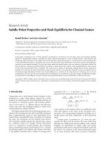
Figure 5: Examples of statistical channel realization (a) and equivalent impulse response (b).
T
g
= 2.048 microseconds. The monocycle (at the transmitter
and receiver front-end) and the channel are simulated with a
sampling period of 2 nanoseconds (63 samples p er mono-
cycle). Then, the front-end filter output signal is downsam-
pled to obtain a period T
c
=16 nanoseconds. Thus, we col-
lect M
= 256 samples per frame and we use an FFT of size
256. The spreading codes have length L
= 16 with a chip
period T
= 128 nanoseconds. The codes are obtained by
the chip-by-chip product of the 16 Wa lsh-Hadamard codes
and a random code for each user to be multiplexed. One
code is reserved for training. We consider binary data sym-
bols. Furthermore, a bit-interleaved convolutional code of
rate 1/2 and memory 4 is used. The transmission rate can
be adjusted according to the number of signature codes that
are allocated to each user. The super-frame spans N
= 540
frames (2.21 milliseconds). Consequently, the coded packet
has length from a minimum of 540 bits with single code, to
a maximum of 8100 coded bits with fulls-rate transmission
(15 codes). A block interleaver that spans 540 frames is used.
With these parameters, the uncoded transmission rate ranges
from 244 kbit/s to 3.66 Mbit/s, while the net rate with coding
is half of that. Clearly, it can be increased w ith higher level
PAM or longer spreading codes, but we have made this choice
to keep the simulation runtime within tolerable values.
6.2. Channel parameters
Starting from the channel model in Section 2.3,wesetB
1
=0
and B
2
= 55 MHz. Having in mind an indoor environment
where the number of paths is typically high, we fix for the
underlying Poisson process an intensity Λ
= 1/15 m
−1
, that
is, one reflector every 15 m in average. The first one is set
at distance 30 m with g
1
= 1, while the maximum path dis-
tance is 300 m. Finally, we choose K
= 1, α
0
= 10
−5
m
−1
,
α
1
= 10
−9
s/m. In Figure 5(a), we plot an example of channel
realization while in Figure 5(b) we plot the equivalent chan-
nel response g
EQ
(t) = g
M
∗ h
(u)
∗ g
FE
(t). The e quivalent re-
sponse is significantly compressed because the monocycle fil-
ters out the low-frequency components that are responsible
for longer channel delays according to model (5). The chan-
nel is assumed to be static for the duration of a super-frame
equal to 2.21 milliseconds, and then it randomly changes. In
the simulations we truncate the channel impulse responses to
4 microseconds. However, we use a guard time of only 2.048
microseconds. The performance degr adation that is due to
the interframe interference that is generated by the tail of the
channelisnegligible.
6.3. Full-rate single-user performance
In Figure 6, we report the bit-error-rate (BER) performance
before channel decoding averaged over at least 1500 PL g rid
topologies (channel realizations) as a function of E
b
/N
0
, that
is, the energy per bit at the front-end output, over the noise
spectral density. The additive background noise is w h ite
Gaussian. We point out that we normalize the channel such
that the received bit energy is constant for all channel real-
izations. This choice removes the fading effect which is ap-
propriate in the PL context differently, for instance, from the
mobile wireless context [18 ]. A single full-rate user that de-
ploys all available 16 Walsh codes is present.
In Figure 6(a), the performance with ideal channel
knowledge is shown for the baseline correlation receiver
(CORR RX), the FD-matched filter detector that takes into
account only the colored noise (FD MF), the FD detector
with single-code transmission (single code), the FD joint it-
erative detector (FD JD-IT) with up to 3 iterations, and fi-
nally the FD full decorrelator (FD F-DEC). All receivers sig-
nificantly improve per formance compared to the baseline
correlation receiver. Since the front-end filter (matched to
10 EURASIP Journal on Advances in Signal Processing
−3036912
E
b
/N
0
(dB)
10
−5
10
−4
10
−3
10
−2
10
−1
10
0
BER
CORR RX
FD MF
FD JD-IT
= 1
FD JD-IT
= 3
FD F-DEC
Single-code bound
(a) Uncoded—ideal channel estimate
−3036912
E
b
/N
0
(dB)
10
−5
10
−4
10
−3
10
−2
10
−1
10
0
BER
FD JD-IT = 1
FD JD-IT
= 3
FD F-DEC
Single-code bound
(b) Uncoded—practical channel estimate
Figure 6: Average BER with one full-rate user without channel coding in AWGN.
the monocycle) colors the noise, the FD MF detector that
takes it into account improves performance compared to the
correlation receiver. However, the severely dispersive channel
introduces intercode interference, thus an error floor is vis-
ible. If we use the FD full decorrelator, we get a significant
performance gain. Here, to simplify complexity, we actu-
ally combine only the frequency bins that have energy above
1% of the maximum. Near ideal performance (single-code
performance bound) is achieved with the FD iterative detec-
tor with only 3 iterations for E
b
/N
o
below 9 dB.
Figure 6(b) shows that with practical channel estimation
(with the method in Section 5.2), the BER performance is
within 1.5 dB from the ideal curves.
In Figure 7(a), we report BER at the output of the soft-
input Viterbi decoder assuming ideal channel estimation,
while in Figure 7(b) we assume practical channel estima-
tion. With channel coding, the performance is improved. The
curves with practical channel estimation are very close to the
ideal curves. Here, curves labeled with EST.IT
= 2 assume
two channel estimation passes using hard feedback from the
decoder (as explained in Section 5.5). With 3 iterative detec-
tion passes, we are w ithin 0.5 dB from the single-code bound
that corresponds to single code transmission and ideal chan-
nel estimation. The simplified F-DEC is within 0.5 dB from
the iterative detector.
In Figure 8(a), we assume the presence of impulse noise
and ideal channel estimation, while in Figure 8(b) we assume
practical channel estimation. We report the BER both with
channel coding (Cod) and without it (Uncod). In the simula-
tion the impulse noise is generated according to the two-term
Gaussian model [21, 22] whose probability density function
can be defined as p
η
(a) = (1−ε)N(0, σ
2
1
)+εN(0, σ
2
2
). The first
term gives the zero-mean Gaussian background noise with
variance σ
2
1
. The second term represents the impulse compo-
nent and it has variance σ
2
2
= 100σ
2
1
.Theoccurrenceproba-
bility is ε
= 0.01. To stress the system performance, when an
impulse occurs, we assume the Gaussian process with vari-
ance σ
2
2
to last for a period of time equal to 4 frames [22].
The spectrum of this noise can be shaped to increase its low-
frequency components to reflect measured scenarios. How-
ever, if we do not do so, we get the worst-case scenario espe-
cially in our system where the transmission spectrum does
Andrea M. Tonello 11
0369
E
b
/N
0
(dB)
10
−5
10
−4
10
−3
10
−2
10
−1
10
0
BER
FD JD-IT = 3
FD F-DEC
Coded single-code bound
Uncoded single-code bound
(a) Coded—ideal channel estimate
0369
E
b
/N
0
(dB)
10
−5
10
−4
10
−3
10
−2
10
−1
10
0
BER
FD JD-IT = 3, EST.IT = 1
FD F-DEC, EST.IT
= 1
FD JD-IT
= 3, EST.IT = 2
FD F-DEC, EST.IT
= 2
Coded single-code bound
Uncoded single-code bound
(b) Coded—practical channel estimate
Figure 7: Average BER with one full-rate user and with channel coding in AWGN.
not occupy the low frequencies. The position of the noise
spikes within a super-frame is estimated. The results show
that a performance degradation is introduced compared to
the AWGN case. However, if we use the proposed modified
Viterbi algorithm (curves labeled with Erasure), the perfor-
mance comes close to that of the single code in AWGN. As
Figure 8(b) shows a second channel estimation pass with
feedback from the decoder yields near-ideal performance.
6.4. Multiuser performance with full-rate users
Users multiplexing can be done by partitioning the L Walsh
codes among the users. To stress the system, we have as-
sumed all users to be at full rate, that is, they deploy all
16 Walsh-Hadamard codes. As explained in Section 2.1,a
random code is also used on top of the Walsh codes. In
Figure 9(a), we assume the presence of one interferer with
ideal channel/correlation estimation while in Figure 9(b) we
assume the presence of three interferers with practical es-
timation. The overall interferers power equals the desired
user power. The channels are independently drawn accord-
ing to the statistical model, however, they are assumed to
be static for the whole duration of a super-frame. The ad-
ditive background noise is white Gaussian. Users are asyn-
chronous with a random starting phase. Figure 9 shows that
although there is some performance penalty compared to
single-code single-user case due to the MAI, the FD detec-
tion algorithms allow to keep such a penalty small. This
can be explained by the fact that the random codes and
the multiple-access channel diversity introduce some de-
grees of freedom that can be exploited in the frequency do-
main by the interference cancellation algorithms. The itera-
tive detector with 3 iterations performs better than the sim-
plified full decorrelator for E
b
/N
o
smaller than 9 dB. Then,
an error floor appears, though it may be reduced with fur-
ther iterations. The simple bit-interleaved memory-4 convo-
lutional code allows to significantly improve the BER perfor-
mance.
With practical estimation (Figure 9(b)) of the channel,
the BER performance exhibits an error floor at the first
12 EURASIP Journal on Advances in Signal Processing
036912
E
b
/N
0
(dB)
10
−5
10
−4
10
−3
10
−2
10
−1
10
0
BER
Uncoded FD JD-IT = 3
Cod FD JD-IT
= 3
Cod FD JD-IT
= 3, erasure
Cod single-code AWGN bound
(a) Impulse noise—ideal channel estimate
036912
E
b
/N
0
(dB)
10
−5
10
−4
10
−3
10
−2
10
−1
10
0
BER
Coded FD JD-IT = 3, EST.IT = 1
Cod FD JD-IT
= 3, EST.IT = 1, erasure
Cod FD JD-IT
= 3, EST.IT = 2, erasure
Cod single-code AWGN bound
(b) Impulse noise—practical channel estimate
Figure 8: Average BER with one full-rate user and with impulse noise.
estimation pass (curves labeled with EST.IT = 1). Here, we
assume to first r un detection and channel decoding without
performing MAI cancellation. For the JD-IT scheme, we run
3 iterations. Then, for the curves labeled with EST.IT
= 2
we rerun a second channel estimation pass followed by prac-
tical estimation of the MAI correlation matrix using hard
feedback from the convolutional decoder. Now, the practi-
cal curves are within about 1 dB from the curves with ideal
channel/correlation estimation.
7. CONCLUSIONS
In this paper, we have investigated the application of wide-
band impulse modulation combined with CDMA for PL
communications. This modulation approach requires a sim-
ple baseband time-domain implementation of the transmit-
ter and the receiver. A key aspect is that the energy of each
information symbol is spread over a wideband (yielding a
low-spectral density signal) contrary to narrowband or mul-
ticarrier architectures that can be seen as a bank of narrow-
band systems. This allows to exploit the channel frequency
diversity and to be robust to narrowband interference. Fur-
ther, time diversity is exploited via the CDMA signature code
together with the bit-interleaved convolutional code. This
yields robustness to impulse noise.
Improved performance, relatively to the baseline corre-
lation receiver, can be obtained with a maximum likelihood
FD joint detector. This receiver adapts to channel time vari-
ations and to asynchronous impulse noise, and mitigates the
detrimental effect of the ICI and MAI that are generated by
the time-dispersive channel and that are significant in full-
rate transmission. With certain simplifications we have de-
rived a simplified FD joint detector, an FD iterative detector,
and an FD interference decorrelator. They all include the ca-
pability of rejecting the ICI/MAI but have different levels of
performance and implementation complexity. In particular,
the FD full decorrelator receiver has the lowest complexity es-
pecially when we process a subset of the available frequency
bins.
Algorithms for the FD estimation of the channel and of
the correlation of the interference have also been described.
Channel estimation can be performed independently over
the frequency bins with one-tap RLS adaptive filters. To im-
prove the performance of the estimators we have used a data
Andrea M. Tonello 13
036912
E
b
/N
0
(dB)
10
−5
10
−4
10
−3
10
−2
10
−1
10
0
BER
Uncoded FD JD-IT = 1
Uncod FD JD-IT
= 3
Uncod FD F-DEC
Cod FD JD-IT
= 3
Cod FD F-DEC
Cod single-user
\code bound
(a) 1 Interferer-ideal channel/correlation estimate
036912
E
b
/N
0
(dB)
10
−5
10
−4
10
−3
10
−2
10
−1
10
0
BER
Coded FD JD-IT = 3 EST.IT = 1
Cod FD F-DEC EST.IT
= 1
Cod FD JD-IT
= 3 EST.IT = 2
Cod FD F-DEC EST.IT
= 2
Cod single-user
\code bound
(b) 3 Interferers-practical channel/correlation es-
timate
Figure 9: Average BER with (a) one and three full-rate interferers (b) (worst-case scenario). (a) Ideal channel/correlation estimation. (b)
Practical estimation of the channel/correlation.
aided approach with hard feedback from the Viterbi decoder.
Few iterations have proved to be effective.
REFERENCES
[1] E. Biglieri, “Coding and modulation for a horrible channel,”
IEEE Communications Magazine, vol. 41, no. 5, pp. 92–98,
2003.
[2] A.M.Tonello,R.Rinaldo,andL.Scarel,“Detectionalgorithms
for wide band impulse modulation based systems over power
line channels,” in Proceedings of the 8th International Sympo-
sium on Power-Line Communications and Its Applications (IS-
PLC ’04), pp. 367–372, Zaragoza, S pain, March-April 2004.
[3] A. M. Tonello, R. Rinaldo, and M. Bellin, “Synchronization
and channel estimation for wide band impulse modulation
over power line channels,” in Proceedings of the 8th Interna-
tional Symposium on Power-Line Communications and Its Ap-
plications (ISPLC ’04), pp. 206–211, Zaragoza, Spain, March-
April 2004.
[4] G. Mathisen and A. M. Tonello, “Wirenet: an experimental
system for in-house powerline communication,” in Proceed-
ings of International Symposium on Power-Line Communica-
tions and Its Applications (ISPLC ’06), pp. 137–142, Orlando,
Fla, USA, March 2006.
[5] M. Z. Win and R. A. Scholtz, “Impulse radio: how it works,”
IEEE Communications Letters, vol. 2, no. 2, pp. 36–38, 1998.
[6] G. Durisi and S. Benedetto, “Performance evaluation and
comparison of different modulation schemes for UWB multi-
access systems,” in Proceedings of IEEE International Conference
on Communications (ICC ’03), vol. 3, pp. 2187–2191, Anchor-
age, Alaska, USA, May 2003.
[7] J. D. Choi and W. E. Stark, “Performance of ultra-wideband
communications with suboptimal receivers in multipath
channels,” IEEE Journal on Selected Areas in Communications,
vol. 20, no. 9, pp. 1754–1766, 2002.
[8] M. Zimmermann and K. Dostert, “A multipath model for the
powerline channel,” IEEE Transactions on Communications,
vol. 50, no. 4, pp. 553–559, 2002.
[9] M. Zimmermann and K. Dostert, “An analysis of the broad-
band noise scenario in power-line networks,” in Proceedings of
the 7th International Symposium on Power-Line Communica-
tions and Its Applications (ISPLC ’00), pp. 131–138, Limerick,
Ireland, April 2000.
14 EURASIP Journal on Advances in Signal Processing
[10] A. M. Tonello and R. Rinaldo, “A time-frequency domain ap-
proach to synchronization, channel estimation, and detection
for DS-CDMA impulse-radio systems,” IEEE Transactions on
Wireless Communications, vol. 4, no. 6, pp. 3018–3030, 2005.
[11] A. M. Tonello, “An impulse modulation based PLC system
with frequency domain receiver processing,” in Proceedings of
the 9th International Symposium on Power-Line Communica-
tions and Its Applications (ISPLC ’05), pp. 241–245, Vancouver,
Canada, April 2005.
[12] A. M. Tonello, “A wide band modem based on impulse mod-
ulation and frequency domain signal processing for power-
line communication,” in Proceedings of the 49th Annual IEEE
Global Telecommunications Conference (GLOBECOM ’06),San
Francisco, Calif, USA, November-December 2006.
[13] M. Z. Win and R. A. Scholtz, “Characterization of ultra-
wide bandwidth wireless indoor channels: a communication-
theoretic view,” IEEE Journal on Selected Areas in Communica-
tions, vol. 20, no. 9, pp. 1613–1627, 2002.
[14] V. Lottici, A. D’Andrea, and U. Mengali, “Channel estimation
for ultra-wideband communications,” IEEE Journal on Selected
Areas in Communications, vol. 20, no. 9, pp. 1638–1645, 2002.
[15] M. V. Clark, “Adaptive frequency-domain equalization and di-
versity combining for broadband wireless communications,”
IEEE Journal on Selected Areas in Communications, vol. 16,
no. 8, pp. 1385–1395, 1998.
[16] J. A. C. Bingham, “Multicarrier modulation for data transmis-
sion: an idea whose time has come,” IEEE Communications
Magazine, vol. 28, no. 5, pp. 5–14, 1990.
[17] M. K. Lee, R. E. Newman, H. A. Latchman, S. Katar, and
L. Yonge, “HomePlug 1.0 powerline communication LANs-
protocol description and performance results,” International
Journal of Communication Systems, vol. 16, no. 5, pp. 447–473,
2003.
[18] J. G. Proakis, Digital Communications,McGraw-Hill,New
York, NY, USA, 3rd edition, 1995.
[19] C. Luschi, M. Sandell, P. Strauch, et al., “Advanced signal-
processing algorithms for energy-efficient wireless communi-
cations,” Proceedings of the IEEE, vol. 88, no. 10, pp. 1633–
1650, 2000.
[20] D. Middleton, “Statistical-physical models of electromagnetic
interference,” IEEE Transactions on Electromagnetic Compati-
bility, vol. 19, no. 3, pp. 106–127, 1977.
[21] R. S. Blum, Y. Zhang, B. M. Sadler, and R. J. Kozick, “On the
approximation of correlated non-Gaussian noise pdfs using
Gaussian mixture models,” in Proceedings of the 1st Conference
on the Applications of Heavy Tailed Distributions in Economics,
Engineering, and Statistics, Washington, DC, USA, June 1999.
[22] H. Dai and H. V. Poor, “Advanced signal processing for
power line communications,” IEEE Communications Maga-
zine, vol. 41, no. 5, pp. 100–107, 2003.
[23] H. Nakagawa, D. Umehara, S. Denno, and Y. Morihiro, “A de-
coding for low density parity check codes over impulse noise
channels,” in Proceedings of the 9th International Symposium on
Power-Line Communications and Its Applications (ISPLC ’05),
pp. 85–89, Vancouver, Canada, April 2005.
[24] R. Pighi, M. Franceschini, G. Ferrari, and R. Raheli, “Fun-
damental performance limits for PLC systems impaired by
impulse noise,” in Proceedings of International Symposium on
Power-Line Communications and Its Applications (ISPLC ’06),
pp. 277–282, Orlando, Fla, USA, March 2006.
[25] G. Ungerboeck, “Adaptive maximum-likelihood receiver for
carrier-modulated data-transmission systems,” IEEE Transac-
tions on Communications, vol. 22, no. 5, pp. 624–636, 1974.
[26] R. M. Buehrer, A. Kaul, S. Striglis, and B. D. Woerner, “Analy-
sis of DS-CDMA parallel interference cancellation with phase
and timing errors,” IEEE Journal on Selected Areas in Commu-
nications, vol. 14, no. 8, pp. 1522–1535, 1996.
[27] A. M. Tonello and F. Pecile, “Synchronization for multiuser
wide band impulse modulation systems in power line chan-
nels with unstationary noise,” in Proceedings of International
Symposium on Power-Line Communications and Its Applica-
tions (ISPLC ’07), Pisa, Italy, March 2007.
Andrea M. Tonello received the Doctor
of engineering degree in electronics (cum
laude) in 1996, and the Doctor of research
degree in electronics and telecommunica-
tions in 2002, both from the University of
Padova, Italy. On February 1997, he joined
as a Member of Technical Staff,BellLabs—
Lucent Technologies, where he worked on
the development of baseband algorithms
for cellular handsets, first in Holmdel, NJ,
and then within the Philips/Lucent Consumer Products Division
in Piscataway, NJ. From September 1997 to December 2002, he has
been with the Bell Labs Advanced Wireless Technology Laboratory,
Whippany, NJ. He was promoted in 2002 to Technical Manager,
and was appointed Managing Director of Bell Labs, Italy. He has
been on leave from the Universit
`
a di Padova, Italy, for part of the
period September 1999–March 2002. In January 2003, he joined
the Dipartimento di Ingegneria Elettrica, Gestionale, e Meccanica
(DIEGM) of the University of Udine, Italy, where he is an Assis-
tant Professor. Dr. Tonello has been involved in the standardization
activity for the evolution of the IS-136 TDMA technology within
UWCC/TIA. He received a Lucent Bell Labs Recognition of Excel-
lence award for his work on enhanced receiver techniques. He is a
Member of the IEEE Communications Society Technical Commit-
tee on Power Line Communications, and he has been TPC Cochair
of the IEEE International Symposium on Power Line Communica-
tions (ISPLC) 2007, Pisa, Italy. He as an Associate Editor for IEEE
Transactions on Vehicular Technology.