Báo cáo hóa học: " Research Article A Method for Source-Microphone Range Estimation in Reverberant Environments Using Arrays of Unknown Geometry" ppt
Bạn đang xem bản rút gọn của tài liệu. Xem và tải ngay bản đầy đủ của tài liệu tại đây (987.56 KB, 10 trang )
Hindawi Publishing Corporation
EURASIP Journal on Advances in Signal Processing
Volume 2008, Article ID 849246, 10 pages
doi:10.1155/2008/849246
Research Article
A Method for Source-Microphone Range Estimation in
Reverberant Environments Using Arrays of Unknown
Geometry
Denis McCarthy and Frank Boland
Department of Electronic and Electrical Engineering, School of Engineering, Trinity College, Dublin, Ireland
Correspondence should be addressed to Denis McCarthy,
Received 18 December 2006; Revised 24 April 2007; Accepted 23 September 2007
Recommended by Joe C. Chen
This paper proposes a technique for determining the distance between a sound source and the microphones in an array. The
proposed “Range-Finder” algorithm is robust in the presence of reverberation and, in contrast with previously published source-
localization techniques, does not require knowledge of the relative positions of the microphones. We discuss the factors affecting
the accuracy of our range estimates and present the results of experiments using simulated and real data to demonstrate the efficacy
of our approach.
Copyright © 2008 D. McCarthy and F. Boland. This is an open access article distributed under the Creative Commons Attribution
License, which permits unrestricted use, distribution, and reproduction in any medium, provided the original work is properly
cited.
1. INTRODUCTION
Estimating the distance between a source and a receiver has
been a central problem in array signal processing since the
earliest days of radar and sonar. For indoor applications,
using microphone arrays, such estimates could have use in
source localization or speaker tracking. In addition, they
could inform decisions regarding microphone selection, al-
lowing us to select the microphone(s) nearest the source or
farthest from some likely interference. Range estimates could
also have use in determining appropriate speech enhance-
ment strategies, such as when deciding whether or not to use
a dereverberation algorithm.
Typically, range is determined by measuring the time-
of-flight of a transmitted or reflected soundwave and mul-
tiplying it by some known propagation speed. In [1] this is
achieved by simultaneous transmission of a soundwave and
a “time-stamped” radio signal. Provided that the transmit-
ter and receiver are synchronized, the time-of-flight may be
easily obtained as the difference in the times of transmission
and reception. However, in a majority of cases the sources of
interest will not be specifically designed transmitters and so
such techniques have limited application.
Given the knowledge of the relative microphone posi-
tions, the source-microphone range may easily be obtained
from estimates of the relative position of the source—an end
to which a variety of solutions have been proposed.
For the sake of clarification, we note that many of the
methods, presented in the literature as “source-localization”
techniques, are, in fact, solutions to the related but distinct
problem of delay-vector estimation, that is, obtaining the rel-
ative intersensor time-delay estimates (TDEs). Furthermore,
in many cases, the source “location” is defined in terms of a
bearing line only. In this paper, we use the term “source lo-
calization” to refer to the problem of estimating the position
of a source, with respect to some coordinate system.
Much of the previously published work on source lo-
calization has focused on the use of TDEs (see [2]and
the references therein for a review of time-delay-estimation
techniques). In the two-dimensional case, source localiza-
tion may be considered a practical application of Apollo-
nius’ problem of tangent circles [3]. The numerical solu-
tion to this problem, as discovered by Vi
`
ete (see [4]fora
description of his solution), may be easily expanded to the
three-dimensional case and, given TDEs between a mini-
mum of four microphones (three in the two-dimensional
case), a source location may be found. In [5], TDEs are deter-
mined for pairs of microphones in a series of four-element,
square microphone arrays. From these, source-bearing lines
are calculated, with the final source location estimate being
2 EURASIP Journal on Advances in Signal Processing
calculated as a weighted average of the closest intersections
between bearing-line pairs. In [6, 7] the authors estimate the
source location via a least-squares fitting of the TDEs for an
ad hoc deployment of sensors.
Relative range estimates may also be obtained from a
comparison of received signal power. In [8] the authors com-
bine TDEs and relative signal power measurements to deter-
mine the location of a source in the extreme near-field of a
two-element array. In [9] the authors present a method for
source localization that utilizes received signal energy only.
Whilst this technique is reported as returning consistently ac-
curate source-bearing estimates, in the presence of reverber-
ation range estimation is shown to be subject to a significant
bias.
The use of techniques employing power measurements
is commonly restricted to nonreverberant acoustic environ-
ments, or to situations where the effects of reverberation are
negligible. This is due to the difficulty inherent in modelling
and/or mitigating against the presence of reverberation and
its consequent adverse effects. Techniques that use TDEs only
are preferred when reverberation is present although, as we
have noted, these require knowledge of the relative micro-
phone positions.
However, for many practical applications, microphone
locations will be unknown or unreliable. Yet, the question of
how to estimate the range between a sound source and a mi-
crophone, in the presence of reverberation and with the rela-
tive positions of the microphones unknown, remains largely
unaddressed. We propose a solution to this problem. Our
method combines relative power measurements with TDEs
in such a way as to mitigate against the adverse effects of
reverberation and obtain absolute source-microphone range
estimates for microphones at unknown locations.
In the following section, we will briefly discuss the rel-
evant characteristics of sound propagation in rooms. In
Section 3, we derive a well-known but na
¨
ıve range estima-
tor as well as the proposed “Range-Finder” algorithm. In
Section 4, we address the factors affecting range-estimate dis-
tribution. In Section 5, we present the results of a series
of simulations and experiments designed to test the per-
formance of our algorithm. We discuss the potential uses
of the Range-Finder algorithm and suggest future work in
Section 6.
2. SOUND PROPAGATION IN ROOMS
In a noiseless but reverberant environment, the signal re-
ceived at some microphone, m
0
, will consist of a direct-path
component and multiple reflected components jointly re-
ferred to as reverberation. The input to the microphone may
be modelled as the convolution of the source-microphone
impulse response, h
0
(t), and the source signal, s(t):
x
0
(t) =
t
0
s(p)h
0
(t − p)dp. (1)
In the frequency domain,
X
0
(ω)
= S(ω)H
0
(ω)
= S(ω)
H
dp
0
(ω)+H
mp
0
(ω)
,
(2)
where H
dp
0
is the component of H
0
due to direct-path (non-
reflected) propagation and H
mp
0
is the reverberant compo-
nent due to multipath reflections. The received signal power
spectrum may be calculated as follows. Note that, for clarity,
we omit the dependence on ω in the sequel
X
0
2
=|S|
2
H
0
2
=|S|
2
H
dp
0
2
+
H
mp
0
2
+2Re
H
dp
0
H
∗
mp
0
,
(3)
where Re
{}denotes the real component and ∗ denotes the
complex conjugate.
In air, for an omnidirectional source and receiver, the
power of the direct-path component of sound, received
at m
0
, is inversely proportional to the squared source-
microphone range, that is, the squared distance between the
source and the microphone,
H
dp
0
2
∝
1
r
2
0
,(4)
where r
0
=|
s
−
m
0
| and
s and
m
0
denote the Cartesian co-
ordinates of the source and m
0
, respectively. The direct-path
component therefore decays at a rate of 6dB per doubling of
the source-microphone range. This model does not address
effects due to variations of air pressure or temperature, how-
ever, in a room environment it is reasonable to assume a ho-
mogenous medium. From (4), we may derive an expression
for the power of the direct-path component of the sound re-
ceived at some microphone m
a
:
H
dp
a
2
=
H
dp
0
2
r
0
r
a
2
. (5)
The reverberant component of an impulse response will
be dependent upon factors such as the dimensions and
surface absorption characteristics of the room. These vary
widely from room to room and so we cannot know
|H
mp
0
|
2
apriori.
Typically, the degree to which a room is reverberant is
described with reference to a metric known as the reverber-
ation time (RT
60
). The RT
60
is defined as the average time
taken for the reverberant sound energy to decay by 60 dB.
Although useful for conveying a general idea of how rever-
berant a room may be, specifying the RT
60
gives no idea of
how reverberant a recorded sound will be. Consider, for ex-
ample, a recording made in a room at a distance of 1 m from
a sound source. This recording will be perceived as being less
reverberant than one made in the same room at 5 m from
the source. This is because the direct path component decays
as we get farther from the source, despite the RT
60
being the
same in each instance.
Amoreeffective way of describing the degree of rever-
beration that obtains on a recording is to specify the direct-
to-reverberant ratio (DRR), that is, the ratio of the received
sound energy due to the direct-path component and mul-
tipath reflections. For a given bandwidth, the DRR at the
D. McCarthy and F. Boland 3
−5
0
5
10
DRR (dB)
−0.4 −0.20 0.20.40.60.811.21.41.6
log
2
(r)
Data
“Best fit”
Office
(a)
−5
0
5
10
15
DRR (dB)
−0.50 0.511.522.5
log
2
(r)
Data
“Best fit”
Classroom
(b)
0
5
10
15
20
DRR (dB)
−0.50 0.511.522.5
log
2
(r)
Data
“Best fit”
Reception hall
(c)
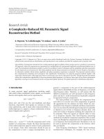
Figure 1: Direct-to-reverberant ratios versus log
2
(r), where r is the
source-microphone range. Results shown are for an office, class-
room, and reception hall.
microphone, m
0
,maybedefinedasfollows:
DRR
0
=
H
dp
0
2
dω
H
mp
0
2
dω
. (6)
An investigation of DRRs in real rooms proves informa-
tive. Figure 1 shows a plot of DRRs, found at a variety of lo-
cationsinanoffice, classroom, and reception hall. The DRRs
are plotted with respect to log
2
(r). The reverberation times
were determined experimentally using the transient decay
method [10]andwerefoundtobe0.6, 0.5, and 1.1 seconds,
respectively. The DRR estimates were obtained as follows.
Recordings were made at varying locations in each room and
at varying distances relative to a single source—in this case a
loudspeaker. The sampling rate was 48 kHz. In each instance,
the microphone was placed directly in front of the loud-
speaker so as to avoid complications due to the directivity of
the source. The loudspeaker produced a maximum-length-
sequence (MLS) of approximate duration 5.5 seconds, also at
a sampling rate of 48 kHz. These recordings were then cross-
correlated with the “clean” MLS to obtain an impulse re-
sponse estimate, from which a DRR estimate was calculated.
Figure 1 also shows “best-fit” linear approximations of
the data. The slopes of these fits are
−6.12, −5.99, and −5.915
decibels per doubling of range for the office, classroom, and
hall, respectively. Given that we can expect
|H
dp
0
|
2
to decay at
a rate of 6 dB per doubling of the source-microphone range,
these results suggest that, in a given room, E
{
|H
mp
0
|
2
dω}
(where E{}is the expectation operator) is a constant that is
independent of the source-microphone range.
We define the following:
F
a,b
=
H
mp
a
2
−
H
mp
b
2
+2Re
H
dp
a
H
∗
mp
a
−H
dp
b
H
∗
mp
b
dω,
(7)
where the a and b subscripts denote the impulse response
components corresponding to the microphones m
a
and m
b
,
respectively. Consider the cross-terms in (7). Direct path
propagation applies a delay and scaling to a sound wave.
Therefore, for any source-microphone impulse response,
H
dp
is a scaled exponential. Similarly, H
mp
may be considered
to be the sum of scaled exponentials corresponding to mul-
tiple reflected sound waves. As such, H
dp
H
∗
mp
is also the sum
of multiple scaled exponentials. Therefore, invoking the cen-
tral limit theorem, we will assume
Re{H
dp
a
H
∗
mp
a
}dω and
Re{H
dp
b
H
∗
mp
b
}dω to be zero-mean normally distributed
random variables. Following from our previous results, we
also assume
|
H
mp
a
|
2
dω and
|
H
mp
b
|
2
dω to be random
variables distributed about the same mean. Therefore, invok-
ing the central limit theorem once again, we may consider
F
a,b
to be a zero-mean normally distributed random variable.
Note that if H
dp
and H
mp
are nonzero at ω = 0,
Re{H
dp
H
∗
mp
}dω will exhibit a positive bias. We may ignore
this, however, as the frequency responses of real microphones
will not have a nonzero component at ω
= 0.
As an aside, we note that a brief inspection of the results
in Figure 1 reveals that although it had the greatest RT
60
, the
reception hall was not the most reverberant of the rooms in
which we took measurements. This further illustrates the in-
adequacy inherent in characterizing the degree of reverbera-
tion in a room by specifying its RT
60
alone. Our results do,
however, suggest an alternative metric. The intercept of best-
fit line with the y-axis defines the spatially averaged “DRR-
at-1 m” and we will use this metric to describe acoustic con-
ditions in the sequel.
3. RANGE ESTIMATION
In this section, we derive two range estimation algorithms:
firstly a well-known but na
¨
ıve range estimator that assumes
an anechoic environment, and secondly the proposed algo-
rithm, which we refer to as the Range-Finder and which is
robust against the effects of reverberation.
4 EURASIP Journal on Advances in Signal Processing
3.1. A na
¨
ıve range estimator
When τ
a
is the relative intersensor time-delay between m
a
and m
0
,
r
a
−r
0
= cτ
a
,(8)
where c is the speed of sound in air. Using any one of a va-
riety of time-delay estimation techniques, we may obtain an
estimate of the relative intersensor time-delay,
τ
a
. In noise-
less, anechoic environments the direct-path sound accounts
for all acoustic energy received by the microphones and so,
by substituting (3)and(8) into (5) and performing algebraic
manipulation, we obtain a simple and well-known estimator
of r
0
:
r
0
=
cτ
a
H
a
2
/
H
0
2
1 −
H
a
2
/
H
0
2
. (9)
Unfortunately, in nonideal acoustic environments, the pres-
ence of interfering reverberation can severely distort this esti-
mate, making the above range estimator unsuitable for use in
practical environments. Where more than two microphones
are available, the most accurate range estimate will be ob-
tained by using only those two microphones closest to the
source. These may be presumed to have the highest DRRs.
The outputs of the remaining microphones will contain pro-
portionally greater levels of reverberation and will, therefore,
lead to greater distortion in the range estimates.
3.2. The Range-Finder algorithm
From (5)and(8),
H
dp
a
2
−
H
dp
b
2
=
H
dp
o
2
r
0
r
0
+ cτ
a
2
−
r
0
r
0
+ cτ
b
2
.
(10)
The term in the square brackets is a function of r
0
, τ
a
,andτ
b
whichwedenoteasG
a,b
(r
0
, τ
a
, τ
b
):
G
a,b
r
0
, τ
a
, τ
b
=
r
0
r
0
+ cτ
a
2
−
r
0
r
0
+ cτ
b
2
. (11)
Integrating (3) across the full bandwidth of the signal, we
obtain P
0
—the total received signal power at m
0
:
P
0
=
|S|
2
H
dp
0
2
+
H
mp
0
2
+2Re
H
dp
0
H
∗
mp
0
dω.
(12)
We de fin e Λ
a,b
as being the difference between the total re-
ceived signal power at m
a
and m
b
:
Λ
a,b
= P
a
−P
b
. (13)
Let us assume, for the moment, that
|S|
2
is a constant with
respect to frequency (we will return to this assumption later).
Substituting (12) into (13) and performing algebraic manip-
ulation yields
Λ
a,b
=|S|
2
kG
a,b
r
0
, τ
a
, τ
b
+ F
a,b
, (14)
where k
=
|
H
dp
0
|
2
dω.From(14), we see that the differ-
ence between the signal power received at two microphones
is proportional to the sum of a scaled, deterministic function,
G
a,b
(r
0
, τ
a
, τ
b
), and a zero-mean and normally distributed
random variable, F
a,b
. We define the following vectors, not-
ing that we have omitted the arguments of the G
a,b
(r
0
, τ
a
, τ
b
)
terms for clarity:
G
=
G
0,1
, G
0,2
, , G
1,2
, G
1,3
, G
M−2,M−1
T
,
F
=
F
0,1
, F
0,2
, , F
1,2
, F
1,3
, F
M−2,M−1
T
,
Λ
=
Λ
0,1
, Λ
0,2
, , Λ
1,2
, Λ
1,3
, Λ
M−2,M−1
T
=|S|
2
[kG + F].
(15)
Once again, using any of the many well-known tech-
niques for delay-vector estimation, we may obtain the time-
delay estimates
τ
a
and τ
b
. We then define
G
a,b
(r
0
) and the
corresponding vector
G(r
0
)from
G
a,b
r
0
=
G
a,b
r
0
, τ
a
, τ
b
. (16)
Following from the Cauchy-Schwartz inequality, the optimal
range estimate,
r
0
, is obtained by a matched-filtering of the
power-difference vector, Λ,with
G(r
0
)/|
G(r
0
)|:
r
0
= arg max
r
0
1
G
r
0
G(r
0
)
T
Λ
. (17)
Following from this estimate, we may easily obtain
estimates of the remaining source-microphone ranges,
{r
1
, r
2
, , r
M−1
}, by inserting r
0
and the TDEs used to cal-
culate
G(r
0
) into (8).
Previously, we assumed
|S(ω)|
2
to be a constant with re-
spect to frequency. In many cases, including that of human
speech, this is unrealistic. In reality, speech is both a lowpass
and often harmonic signal. This poses particular problems.
We have assumed F
a,b
to be a zero-mean, normal random
variable. The analysis and experimental evidence underpin-
ning this assumption are for broadband signals and we can-
not reasonably expect it to hold for cases, such as speech,
where the bulk of the energy is concentrated at low frequen-
cies.
This problem was overcome as follows. The microphone
outputs are split into individual, nonoverlapping subbands.
The bandwidth of these subbands are chosen such that they
are narrow enough that
|S(ω)|
2
is roughly constant within
the subband whilst also being wide enough that there is al-
ways a direct-path speech component present. Λ is then cal-
culated for each subband. Each Λ is normalized and, from
these, an average power-difference vector,
Λ,isfoundacross
all the subbands. The range estimate is found, as in (17)bya
matched filtering of
Λ with
G(r
0
)/|
G(r
0
)|.
4. ESTIMATE DISTRIBUTION AND ACCURACY
Given multiple estimates for range, we might expect that, as
the number of estimates increases, their mean will approach
the true range. As we will see in the following section, this
D. McCarthy and F. Boland 5
is not necessarily the case. We will also show how the accu-
racy of a range estimate is dependant upon the actual source-
microphone ranges. We restrict our analysis to the situa-
tion where we have three microphones only—the minimum
number required to implement the Range-Finder. We do this
both for the sake of simplicity and to allow us to employ an
alternative formulation of the Range-Finder algorithm. This
alternative formulation more clearly illustrates how the dis-
tribution of range estimates is related to the distribution of
the ratio of normal random variables, a well-understood, al-
beit nontrivial, distribution that has received extensive study
in the literature.
4.1. An alternative formulation of the Range-Finder
The range estimate,
r
o
, is that which maximizes the expres-
sion in (17). For two vectors with given norms, the dot prod-
uct of the vectors is a maximum when they are propor-
tional. Therefore, we may write
G(r
0
) ∝ Λ. For the three-
microphone case, this implies
G
0,1
r
0
,
G
0,2
r
0
∝
Λ
0,1
, Λ
0,2
. (18)
Using an equivalent expression, we define Q
0,1,2
:
G
0,1
r
0
G
0,2
r
0
=
Λ
0,1
Λ
0,2
= Q
0,1,2
, (19)
and from this, we obtain an alternative formulation for the
Range-Finder:
r
0
= arg min
r
0
Q
0,1,2
−
G
0,1
r
0
G
0,2
r
0
. (20)
For 3 microphones there are, of course, 5 further permuta-
tions of Q (Q
0,2,1
, Q
1,2,0
,etc.).However,allmaybeshownto
yield identical range estimates and so we will consider only
Q
0,1,2
. Furthermore, to simplify our analysis, we will assume
that 0
≤ τ
1
≤ τ
2
. We note that this relationship is for sim-
plicity only and is not an absolute requirement. Rather, it is
merely a result of the arbitrary way in which we assign labels
to the microphones. Once again, omitting the arguments of
the G
a,b
(r
0
, τ
a
, τ
b
) terms for clarity:
Q
0,1,2
=
G
0,1
+
F
0,1
/k
G
0,2
+
F
0,2
/k
. (21)
From (21), we see that Q
0,1,2
is the ratio of normally dis-
tributed and correlated random variables, with unknown
variances and means of G
0,1
and G
0,2
,respectively.Suchara-
tio is itself a Cauchy distributed random variable.
4.2. Cauchy distribution
In [11] it is shown that, following a translation and a change
of scale, Q
0,1,2
has the same distribution as the ratio of two
uncorrelated normal random variables of unity variance,
N(α,1)/N(β,1). The real constants α and β may be calculated
as follows:
α
=±
G
0,1
/σ
0,1
−ρG
0,2
/σ
0,2
1 −ρ
2
, β =
G
0,2
σ
0,2
, (22)
where σ
a,b
is the standard deviation of (F
a,b
)/k, ρ is the cor-
relation between Λ
0,1
and Λ
0,2
(which may be shown to be
0.5), and the sign of α is chosen to be the same as that of β.
For the sake of simplicity and to avoid unwieldy equations,
the following discussion will be with reference to the simpli-
fied standard form N(α,1)/N(β,1).From[12], the probabil-
ity density function (PDF), p(t), of N(α,1)/N(β,1)may be
given as shown below:
p(t)
=
exp
−
0.5
α
2
+β
2
π
1+t
2
1+q exp
0.5q
2
q
0
exp
−0.5x
2
dx
,
q
=
β + αt
√
1+t
2
.
(23)
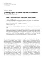
Figure 2 shows the PDFs for varying values of α and β.
A very wide variety of distribution shapes are possible and
the ones shown are chosen for specific illustrative purposes.
For a more complete selection of graphs please see [12].
Shown also is α/β (dashed line). In Figure 2, the distribu-
tions are not symmetric about α/β. In addition and contrary
to what we might expect, the “mean” of N(α,1)/N(β,1) is
not α/β. In fact, strictly speaking, the mean and variance of
N(α,1)/N(β,1) do not exist. This is because N(α,1)/N(β,1)
is undefined when the denominator equals zero.
In practice, we may calculate a pseudomean and pseu-
dovariance by considering only those estimates that fall
within certain bounds. A natural bound would be that value
of Q
0,1,2
corresponding to a range estimate of zero meters
(negative range estimates cannot be correct). In setting such
bounds, however, we should be mindful that the consequent
truncation of the PDF may introduce a bias into the pseu-
domean.
In general, when defined within sufficiently wide bounds,
the pseudomean tends towards α/β for
|α|, |β|1, as oc-
curs when G
0,b
σ
0,b
. Furthermore, under these condi-
tions, Q
0,1,2
tends to have quite a narrow distribution (see
Figure 2(c)). Unfortunately, the converse is also the case.
In general, without knowing σ
0,1
or σ
0,2
, we cannot calcu-
late/estimate the distribution of Q
0,1,2
and, hence, cannot
quantify the bias that any given bounds may introduce. We
can, however, identify certain situations in which such a bias
is likely to be very large. Consider the case where r
0
cτ
b
,
that is, when the array is remote from the source. From in-
spection of (11), we see that under these conditions, G
0,b
→0.
As a result, Q
0,1,2
is widely distributed, causing our range es-
timates to exhibit a large variance and, depending upon the
bounds used, the mean of the range estimates to be subject
to a potentially large bias.
4.3. The effect of array geometry
The actual source-microphone ranges determine the values
of r
0
, τ
1
and τ
2
. We have seen how these parameters can affect
the distribution of Q
0,1,2
and bias its pseudomean away from
G
0,1
/G
0,2
. In this respect, therefore, the accuracy with which
we may estimate range is determined by the array geome-
try. Array geometry also determines the extent to which a
6 EURASIP Journal on Advances in Signal Processing
0
0.1
0.2
0.3
0.4
0.5
0.6
012
t
[α, β]
= [0.25, 0.5]
(a)
0
0.1
0.2
0.3
0.4
0.5
0.6
0123
t
[α, β]
= [2, 2]
(b)
0
0.5
1
1.5
2
2.5
3
0123
t
[α, β]
= [10, 10]
(c)
Figure 2: Portions of the PDFs of N(α,1)/N (β, 1), also shown is α/β (dashed line).
bias/error in Q
0,1,2
translates into an error in the correspond-
ing range estimate. To investigate this second effect of array
geometry, we examine how a fixed bias, ξ, translates into an
error in the range estimate.
Consider an estimate,
r
0
, of the true range, r
0
, and let us
assume that this estimate contains some error,
0
:
G
0,1
r
0
G
0,2
r
0
=
Q
0,1,2
=
G
0,1
G
0,2
+ ξ. (24)
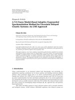
As an illustrative example, we plot G
0,1
/G
0,2
against r
0
for
[cτ
1
, cτ
2
] = [1 m,5m] in Figure 3. Outside of a small region
around r
0
= 0, as r
0
increases the slope of the graph reduces
and
0
becomes larger.
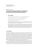
Figure 4, showing
|(d/dr
0
)(G
0,1
/G
0,2
)| with respect to
cτ
1
/r
0
and cτ
2
/r
0
, provides a more complete description
of how array geometry affects estimate accuracy. Note that
the region where cτ
2
/r
0
< 1 is not shown as in this re-
gion
|(d/dr
0
)(G
0,1
/G
0,2
)|→∞, obscuring the remaining de-
tail in the graph. However, it is the region where (r
0
+
cτ
1
)/r
0
≈ (r
0
+ cτ
2
)/r
0
that is of particular interest. Here,
|(d/dr
0
)(G
0,1
/G
0,2
)| approaches zero leading to a very large
0
. In the extreme case, where τ
1
= τ
2
,norangeestimate
may be found as G
0,1
/G
0,2
will be unity for all values of r
0
.
Similarly, no range estimate may be found if τ
1
or τ
2
equals
zero, as G
0,1
/G
0,2
will be zero or undefined, respectively, for
all values of r
0
.
The analysis in this section has been limited to the three
microphone case. However, the results of our analysis have
implications for implementations of the Range-Finder us-
ing any number of microphones. To obtain accurate range
estimates, we require access to a minimum of three micro-
phones for which no two are equidistant (or approximately
equidistant) from the sound source. Furthermore, we will
0.4
0.5
0.6
0.7
0.8
0.9
1
G
0,1
G
0,2
00.511.522.533.544.55
r
0
(m)
ξ
ξ
0
0
[cτ
1
, cτ
2
] = [1 m, 5 m]
Figure 3: G
0,1
/G
0,2
versus r
0
for [cτ
1
, cτ
2
] = [1 m, 5 m]. Range esti-
mate error increases with r
0
.
not achieve accurate range estimation when r
0
cτ
1
, cτ
2
.
Under such conditions we may expect Q
0,1,2
to exhibit a
wide distribution and significant bias. This bias/error will
then translate into a large error in the range estimate due to
(r
0
+ cτ
1
)/r
0
≈ (r
0
+ cτ
2
)/r
0
.
We should not, therefore, apply the Range-Finder al-
gorithm in what might be considered the classical micro-
phone array scenario, that of closely spaced microphones
and a distant, “farfield” source. Rather, successful implemen-
tation would require microphones to positioned in such a
way that they are unlikely to be equidistant from the source
and, ideally, we will have access to at least 3 microphones for
D. McCarthy and F. Boland 7
0
0.5
1
1.5
2
2.5
3
3.5
4
cτ
1
r
0
11.522.533.544.55
cτ
2
r
0
0.05
0.1
0.15
0.2
0.25
d
dr
0
G
0,1
G
0,2
Figure 4: |(d/dr
0
)(G
0,1
/G
0,2
)| with respect to cτ
1
/r
0
and cτ
2
/r
0
.
[0 m, 0 m,0 m]
[5.25 m, 6.95 m,2.44 m]
S
1
S
2
S
3
m
0
m
1
m
2
m
3
m
4
m
5
Figure 5: A diagram of the simulated room and setup. For precise
coordinates of the microphones and loudspeakers, see Ta bl e 1.
which r
0
cτ
1
cτ
2
. We will discuss this further and
consider the potential applications of the Range-Finder al-
gorithm in Section 6.
5. SIMULATIONS AND EXPERIMENTS
5.1. Simulations
A series of simulations were performed to examine the per-
formance of the Range-Finder algorithm and compare it to
that of the na
¨
ıve range estimator under varying reverberant
conditions. Our simulated environment, Figure 5,wasasim-
ple rectangular room of dimensions [5.25m, 6.95 m,2.44m]
and uniform surface absorption coefficient of 0.3. In this
room, we simulated three omnidirectional sources and six
omnidirectional microphones (see Ta bl e 1 for coordinates).
The sampling frequency used was 10 kHz. The source-
microphone impulse responses were generated using an
acoustic modeling software package [13]. A ray tracing al-
gorithm was used to determine first 20 milliseconds of the
impulse response after and including the arrival of the direct-
Table 1: The coordinates of the microphone and source locations
for the simulated room. Coordinates are in meters.
(m) m
0
m
1
m
2
m
3
m
4
m
5
S
1
S
2
S
3
x 33224412.54
y 4332215.55.55.5
z 212121111
path component. Statistical, random reverberant tails were
used for the remaining reflections. Two “source signals”—
a maximum-length sequence (MLS) of 5.5 seconds in du-
ration and concatenated voice samples of approximately 13
seconds total duration, both bandlimited to avoid aliasing—
were convolved with each impulse response to obtain the
simulated “recordings.” The TDEs were calculated geomet-
rically, using the source and microphone coordinates and a
known speed of sound.
The recordings were split into segments of 8192 sam-
ples and windowed using a Hamming window. The segment
overlap was 50%. In the case of the speech recordings, the sig-
nals were separated into eight nonoverlapping subbands with
bandwidth 10/16 kHz and
Λ was determined as described
in Section 3. For each segment, the Range-Finder algorithm
(original formulation (17)) was then used to estimate the
distance between the sources and each of the microphones.
Negative range estimates and estimates greater than 5 m were
ignored—having been determined that wider boundaries did
not increase the accuracy of the range estimates.
To investigate the effect of reverberation, the DRR at 1 m
of the simulated room was varied by applying an appropriate
scaling to the direct-path components of the simulated im-
pulse responses. Range estimates were then obtained as pre-
viously described. The results for each source are shown in
Figures 6 and 7. The mean of the range estimates,
±one stan-
dard deviation, is shown with respect to the DRR at 1 m. The
results shown relate to the estimates of r
0
only. Estimates of
the remaining ranges (r
1
to r
5
) are omitted because, as is ap-
parent from (8), these will exhibit an identical bias and dis-
tribution to those corresponding to r
0
. Note that m
0
is the
closest microphone to each source. The estimates of r
0
will,
therefore, exhibit the greatest percentage error.
The means of the results obtained using the voice record-
ings are slightly more accurate than those found using the
MLS recordings, albeit with a significantly greater variance.
Each set of graphs shows that the range estimates are sub-
ject to a negative bias that reduces as the reverberation levels
decrease. In Section 4.2, we discussed the factors that may ex-
plain the presence of a bias in the range estimates. While it is
not necessarily the case that any such bias should be nega-
tive, from inspection of the PDFs in Figure 2 we see that the
density below the mean tends to be greater than that above.
Therefore, we may speculate that, for a finite number of esti-
mates, any bias present would tend to be negative, although
the precise nature of such a bias is ultimately determined by
the reverberation levels present and the array geometry and
estimate bounds used.
In Figure 8, the performance of the Range-Finder al-
gorithm is compared to that of the na
¨
ıve range estimator
8 EURASIP Journal on Advances in Signal Processing
1
1.5
2
2.5
3
3.5
Range (m)
678910111213141516
DRRat1m(dB)
Source 1
(a)
0
0.5
1
1.5
2
2.5
Range (m)
678910111213141516
DRRat1m(dB)
Source 2
(b)
0
0.5
1
1.5
2
2.5
Range (m)
678910111213141516
DRRat1m(dB)
Source 3
(c)
Figure 6: Mean range estimates ± standard deviation for source
producing an MLS.
derived in Section 3. The estimates made using the na
¨
ıve
range estimator were found using the two microphones clos-
est to the source so as to achieve the best possible results.
TheresultsshownareforSource2butareillustrativeof
the results obtained for the other sources. In both the voice
and MLS cases, the Range-Finder algorithm outperforms the
na
¨
ıve range estimator.
5.2. Experiments
A series of recordings were made to test the Range-Finder
under real conditions. The room used was the office, which
was chosen for being a highly reverberant environment that
would best highlight the superior performance of the Range-
Finder over the na
¨
ıve range estimator. Six microphones were
positioned at distances of between 0.8mand3mfroma
loudspeaker, at intervals of roughly 0.5 m. The loudspeaker
and microphones were arranged so as to be approximately
colinear, so as to avoid errors due to the directionality of the
source. Voice and MLS signals were produced by the loud-
speaker. The microphone outputs were recorded before being
bandlimited and downsampled to a sampling rate of 10 kHz.
These recordings were then split into segments of 8192 sam-
ples and windowed using a Hamming window. The segment
overlap was 50%. The TDEs were found using a PHAT-GCC
[14] and range estimates were obtained for each segment.
1
1.5
2
2.5
3
3.5
Range (m)
678910111213141516
DRR at 1 m (dB)
Source 1
(a)
0
0.5
1
1.5
2
2.5
Range (m)
678910111213141516
DRR at 1 m (dB)
Source 2
(b)
0
0.5
1
1.5
2
2.5
Range (m)
678910111213141516
DRR at 1 m (dB)
Source 3
(c)
Figure 7: Mean range estimates ± standard deviation for a voice
source.
This procedure was repeated for each of three setups in which
the loudspeaker and microphones were arranged colinearly
along the length and each diagonal of the office, respectively.
The results are shown in Figure 9 and, as with the simu-
lations, clearly show the superior performance of the Range-
Finder method. As before, the variances of the results found
using voice recordings are greater than those found using
MLS recordings, however, there is no noticeable trend with
respect to the bias in the mean of the estimates.
6. DISCUSSION
We have proposed a method for estimating source-
microphone ranges that is robust against the effects of rever-
beration. We have discussed the factors affecting the distri-
bution and accuracy of the range estimates obtained by our
method and have presented simulated and real experimental
results demonstrating its efficacy.
In contrast with source-localization techniques, our
method requires no information regarding microphone loca-
tions in order to return a range estimate. However, our anal-
ysis in Section 4 revealed that the accuracy of the range esti-
mates so obtained is, nonetheless, affected by the relative po-
sitioning of the microphones and the sound source. In par-
ticular, it was found that we can expect the range estimates to
be inaccurate if r
0
cτ
1
, cτ
2
, , cτ
M−1
. Rather, successful
D. McCarthy and F. Boland 9
0
1
2
3
4
5
Range (m)
6 7 8 9 10 11 12 13 14 15 16
DRRat1m(dB)
MLS source
Na
¨
ıve estimator
Range-Finder
(a)
0
1
2
3
4
5
Range (m)
6 7 8 9 10 11 12 13 14 15 16
DRRat1m(dB)
Vo ic e s o ur ce
Na
¨
ıve estimator
Range-Finder
(b)
Figure 8: A comparison of mean range estimates (±one standard deviation) for the na
¨
ıve range estimator and the Range-Finder algorithm.
0
0.5
1
1.5
2
Range (m)
123
Setup
MLS
Range-Finder
Tr ue r a ng e
Na
¨
ıve estimator
(a)
0
0.5
1
1.5
2
2.5
Range (m)
123
Setup
Vo ic e
Range-Finder
Tr ue r a ng e
Na
¨
ıve estimator
(b)
Figure 9: Mean range estimates ± standard deviation from real-room recordings.
implementation of the Range-Finder requires that the micro-
phones be positioned such that there is a sufficient “spread”
in the distances from the source to each microphone.
This then precludes the application of the Range-Finder
method to the classical scenario of closely spaced micro-
phones and a farfield source. Nonetheless, there are sev-
eral scenarios in which this requirement is likely to be met
and, hence, to which we may successfully apply the Range-
Finder method. Consider, for example, the case in which it
is required to capture the contributions of a large and dis-
tributed group of talkers using a finite number of remote
microphones. Under such conditions, it may be found that
the classical approach of concentrating the microphones in
a closely spaced array causes many of the participants to be
a significant distance from all available microphones. As the
DRR of recorded sound reduces with increasing distance (see
Figure 1) this could cause the contributions from some talk-
ers to be degraded unacceptably. We may, then, prefer to dis-
tribute the microphones throughout or around the group
of participants such that every potential talker is sufficiently
close and has unobstructed access to at least one micro-
phone. Given the wide distribution of the microphones, it
is also likely that, when the sound source is any given talker,
we will have access to at least three microphones for which
r
0
cτ
1
cτ
2
. We may, therefore, expect accurate range
estimates.
We also note that it is often most advantageous to be able
to estimate source-microphone ranges in scenarios in which
these are not equal for all microphones (so that we may de-
termine which microphones are closest/farthest away, etc.).
In addition, when microphones are widely separated, deter-
mining their relative locations is likely to be cumbersome and
prone to error. Where microphones are frequently moved,
say in response to changes in the distribution of participant
talkers, it may not be practical to measure microphone loca-
tions at all. The Range-Finder algorithm is, therefore, most
effective in precisely those scenarios in which it may be re-
quired to estimate source-microphone ranges in the absence
of reliable microphone-location information.
Our analysis in Section 4 identified scenarios in which
the Range-Finder is likely to be inaccurate. Conversely, how-
ever, it is possible to specify situations in which the Range-
Finder will perform well where many source-localization
techniques fail completely. Consider, for example, a situation
10 EURASIP Journal on Advances in Signal Processing
in which the microphones and sound source are colinear. For
such a setup, the intersensor time delays will be identical for
all r
0
(assuming that the source is not in the interior of the
array). As a result, no TDE-based localization technique can
return a unique estimate of r
0
. Where the source and micro-
phones are nearly colinear, we can expect significant error in
our range estimates due to errors in the TDEs.
It is apparent, therefore, that the relative positions of the
microphones and sound source have a significant bearing
upon the accuracy or otherwise of source localization algo-
rithms as well as that of the Range-Finder method. For this
reason, any experimental comparisons made between their
relative performances would yield scenario-specific results
that could not be considered valid in general.
So far, we have assumed an omnidirectional source. In
doing so, we have ignored a very pressing practical problem.
In reality, sources of interest are likely to be directional and
the received sound intensity will depend not only upon the
microphone’s distance from the source but also its relative
azimuth and elevation. If the azimuth-elevation-dependant
gain were known for each microphone, it could easily be in-
cluded in our formulation of the Range-Finder. However, we
are unlikely to have such information, or, indeed, to know
the orientation of the source relative to the microphones.
A further complicating factor is that source directionality
is frequency-dependant, with sources typically becoming in-
creasingly directional with frequency.
We should, however, be careful not to overstate the diffi-
culties that directionality presents. Some studies would sug-
gest that directivity would not be a significant factor at fre-
quencies below 4 kHz and within an azimuth of
±30
◦
rela-
tive to the direction in which a talker is facing [15]. If we
could assume that the microphones were within some an-
gular boundaries relative to the source, then we may ap-
ply the Range-Finder with confidence. Yet, in the absence of
comprehensive data regarding azimuth-elevation-dependant
gain for the source of interest, it is hard to see how we
might specify and justify the required angular boundaries.
We therefore require such data and are limited in application
when it is not available.
We note that not all microphones need to be within the
specified boundaries; only a minimum of 3 need be and the
remaining ranges may be found from the TDEs. Future work
will focus on determining the directionality of typical sources
and on methods for automatically determining which, if any,
of the microphones we should use in the presence of a direc-
tional source.
We also note that, when the source and microphones
are colinear, the directionality of the source does not pose
a problem. However, as previously mentioned, given such
a setup, TDE-based source localization techniques will fail.
This, therefore, suggests a role for the Range-Finder as an
auxiliary source localization algorithm.
ACKNOWLEDGMENTS
The support of the Informatics Commercialisation initiative
of Enterprise Ireland is gratefully acknowledged. Denis Mc-
Carthy also acknowledges the financial support, from Trinity
College, of a postgraduate studentship.
REFERENCES
[1] L. Girod and D. Estrin, “Robust range estimation using acous-
tic and multimodal sensing,” in Proceedings of IEEE/RSJ Inter-
national Conference on Intelligent Robots and Systems (IROS
’01), vol. 3, pp. 1312–1320, Maui, Hawaii, USA, October-
November 2001.
[2] J. Chen, J. Benesty, and Y. Huang, “Time delay estimation in
room acoustic environments: an overview,” EURASIP Journal
on Advances in Signal Processing, vol. 2006, Article ID 26503,
19 pages, 2006.
[3] D.GischandJ.M.Ribando,“Apollonius’problems:astudyof
their solutions and connections,” American Journal of Under-
graduate Research, vol. 3, no. 1, pp. 15–26, 2004.
[4] E. W. Weisstein, ““Apollonius’ Problem” from MathWorld-
A wolfram web resource,” />ApolloniusProblem.html.
[5] M. S. Brandstein, J. E. Adcock, and H. F. Silverman, “A closed-
form method for finding source locations from microphone-
array time-delay estimates,” in Proceedings of IEEE Interna-
tional Conference on Acoustics, Speech and Signal Processing
(ICASSP ’95), vol. 5, pp. 3019–3022, Detroit, Mich, USA, May
1995.
[6] K.Yao,R.E.Hudson,C.W.Reed,D.Chen,andF.Lorenzelli,
“Blind beamforming on a randomly distributed sensor array
system,” IEEE Journal on Selected Areas in Communications,
vol. 16, no. 8, pp. 1555–1567, 1998.
[7] Y.Huang,J.Benesty,G.W.Elko,andR.M.Mersereau,“Real-
time passive source localization: a practical linear-correction
least-squares approach,” IEEE Transactions on Speech and Au-
dio Processing, vol. 9, no. 8, pp. 943–956, 2001.
[8] H. Teutsch and G. W. Elko, “An adaptive close-talking micro-
phone array,” in Proceedings of IEEE Workshop on Applications
of Signal Processing to Audio and Ac oustics (ASSP ’01), pp. 163–
166, New Paltz, NY, USA, October 2001.
[9] S. T. Birchfield and R. Gangishetty, “Acoustic localization by
interaural level difference,” in Proceedings of IEEE International
Conference on Acoustics, Speech and Signal Processing (ICASSP
’05), vol. 4, pp. 1109–1112, Philadelphia, Pa, USA, March
2005.
[10] K. S. Sum and J. Pan, “On the steady-state and the transient de-
cay methods for the estimation of reverberation time,” Journal
of the Acoustical Soc iety of America, vol. 112, no. 6, pp. 2583–
2588, 2002.
[11] G. Marsaglia, “Ratios of normal variables,” Journal of Statisti-
cal Software, vol. 16, no. 4, pp. 1–10, 2006.
[12] G. Marsaglia, “Ratios of normal variables and ratios of sums
of variables,” Journal of the American Statistical Association,
vol. 60, no. 309, pp. 193–204, 1965.
[13] EASE, “Enhanced acoustic simulator for engineers,” version
4.0, />[14] C. H. Knapp and G. C. Carter, “Generalized correlation
method for estimation of time delay,” IEEE Transactions on
Acoustics, Speech, and Signal Processing, vol. 24, pp. 320–327,
1976.
[15] J. Huopaniemi, K. Kettunen, and J. Rahkonen, “Measurement
and modeling techniques for directional sound radiation from
the mouth,” in Proceedings of IEEE Workshop on Applications of
Signal Processing to Audio and Acoustics (ASSP ’99), pp. 183–
186, New Paltz, NY, USA, October 1999.