Báo cáo hóa học: " Research Article Automatic Eye Winks Interpretation System for Human-Machine Interface" pdf
Bạn đang xem bản rút gọn của tài liệu. Xem và tải ngay bản đầy đủ của tài liệu tại đây (2.5 MB, 9 trang )
Hindawi Publishing Corporation
EURASIP Journal on Image and Video Processing
Volume 2007, Article ID 65184, 9 pages
doi:10.1155/2007/65184
Research Article
Automatic Eye Winks Interpretation System for
Human-Machine Inter face
Che Wei-Gang,
1
Chung-Lin Huang,
1, 2
and Wen-Liang Hwang
3
1
Department of Electrical Engineering , National Tsing-Hua University, Hsin-Chu, Taiwan
2
Department of Informatics, Fo-Guang University, I-Lan, Taiwan
3
Institute of Information Science, Academic Sinica, Taipei, Taiwan
Received 2 January 2007; Revised 30 April 2007; Accepted 21 August 2007
Recommended by Alice Caplier
This paper proposes an automatic eye-wink interpretation system for human-machine interface to benefit the severely handi-
capped people. Our system consists of (1) applying the support vector machine (SVM) to detect the eyes, (2) using the template
matching algorithm to track the eyes, (3) using SVM classifier to verify the open or closed eyes and convert the eye winks into a
sequence of codes (0 or 1), and (4) applying the dynamic programming to translate the code sequence to a certain valid command.
Different from the previous eye-gaze tracking methods, our system identifies the open or closed eye, and then interprets the eye
winking as certain commands for human-machine interface. In the experiments, our system demonstrates better performance as
well as higher accuracy.
Copyright © 2007 Che Wei-Gang et al. This is an open access article distributed under the Creative Commons Attribution License,
which permits unrestricted use, distribution, and reproduction in any medium, provided the original work is properly cited.
1. INTRODUCTION
Recently, there has been an emerging community of ma-
chine perception scientists focusing on automatic eye detec-
tion and tracking research. It can be applied for vision-based
human-machine interface (HMI) applications such as moni-
toring human vigilance [1–6] and assisting the disable [7, 8].
The eye detection and tracking approaches can be classified
into two categories: CCD camer a-based approaches [1–11]
and active IR-based approaches [12–15].
An eye-wink control interface [7] is proposed to provide
the severely disabled with increased flexibility and comfort.
The eye tr acker [2] makes use of a binary classifier with a dy-
namic training strategy and an unsupervised clustering stage
to efficiently track the pupil (eyeball) in real time. Based on
optical flow and color predicates, the eye tracking [4]canro-
bustly track a person’s head and facial features. It classifies
the rotation of all viewing directions, detects eye blinking,
and recovers the 3D gaze of the eyes. In [5], the eye detec-
tion operates on the entire image, looking for regions that
have the edges with a geometrical configuration similar to
the expected one of the iris. It uses the mean absolute er ror
measurement for eye tracking and a neural network for eyes
validation.
The eye movement collection data can be analyzed to de-
termine the pattern and duration of eye fixations and the se-
quence of scan path as a user visually moves his eyes. The
eye tracking researches, such as the eye-gaze estimation [2, 9]
and eye blink rate analysis [3–5], can be applied to analyze
the fatigue and deceit of human being [6]. Another applica-
tion such as head-mounted goggle type eye detection device
[10] with a liquid crystal display is developed for investiga-
tion of eye movements of neurological disease patients. In
[11], they formulate a probabilistic image model and derive
optimal inference algorithms for finding objects. It requires
the likelihood-ratio models for object versus backg round,
which can be applied to find faces and eyes on arbitrary im-
ages.
The active approaches [12–15] make use of IR devices for
the purposes of pupil tracking based on the special bright
pupil effect. This is a simple and very accurate approach
to pupil detection using the differential infrared lighting
scheme. By combining imaging by using IR light and ob-
ject recognition techniques, the method proposed in [14]
can robustly track eyes even when the pupils are not very
bright due to significant external illumination interference.
The eye detection and tracking process is based on the sup-
port vector machine (SVM) and mean shift tracking. An-
other method [15] exhibits robustness to light changes and
camera defocusing. It is capable of handling sudden changes
between IR and non-IR light conditions, without changing
parameters.
2 EURASIP Journal on Image and Video Processing
Locating face in the next
frame
No
Yes
No
Yes
No
Yes
Face found
Eye detection using SVM
Eye found
Update eye template
Identify open or closed eye
Command interpreter using
dynamic programming
Tracking eye using template
matching
Eye matched
Figure 1: Flowchart of the eye-winks interpretation system.
However, the active methods [12–15] require additional
resources in the form of infrared sources and infrared sen-
sors. Here, we propose a vision-based eye-wink control inter-
face for helping the severely handicapped people to manip-
ulate the household dev ices. Recently, many researchers have
shown great interests in the research topics of HMI. In this
paper, we propose an eye-wink control HMI system which
allows the severely handicapped people to control the appli-
ances by using their eye winks. We assume that the possi-
ble head poses of the handicapped people are very limited.
Under the front-pose assumption, we may easily locate the
eyes, track the eyes, and then identify the open or closed
eye.
Before eye tracking, we use the skin color information to
find the possible face region w hich is a convex region larger
than a certain size. Once the face region is found, we define
the possible eye region in which we may apply SVM to lo-
calize the eyes precisely and create the eye template obtained
from the identified eye image. In the next frame, we apply the
template matching to track the eyes based on the eye template
extracted in the previous frame. The eye template is updated
every time the eye is successfully tracked. After eye tracking,
we apply SVM to verify whether the tracked block is an eye
or a noneye region. If it is an eye region, then we use SVM
again to identify whether it is an open eye or a closed eye,
and then convert the eye winks to a sequence of 1 or 0 codes.
Finally, we apply the dynamic programming to validate the
code sequence and convert the code sequence into a certain
command. The flow chart of the proposed system is illus-
trated in Figure 1.
2. EYE DETECTION AND TRACKING
Our eye detection and tracking method consists of three
stages: (1) face region detection, (2) eye localization, and (3)
eye tracking. The three steps are illustrated in the following
sections.
2.1. Face region detection
To reduce the eye search region, we need to locate the pos-
sible face region. In the captured human face images, we as-
sume that the color distribution of the human face is some-
how different from that of the image background. Pixels be-
longing to face region exhibit similar chrominance values
within and across people of different ethnic groups [16].
However, the color of face region may be affected by different
illuminations in the indoor environment. For skin color de-
tection, we analyze the color of the pixels in HSI color space
to decrease the effect of illumination changes, and then clas-
sify the pixels into face color or nonface color based on their
hue component only.
Similar to [17], we analyze the statistics of skin color and
nonskin color distributions from a set of training data to
obtain the conditional probability density functions of skin
color, and nonskin color. From 100 training close-up face im-
ages, we have the probability density function of hue value
H, which can be either face color and nonface color (i.e.,
p(H—face) and p(H—nonface)). Based on hue statistics, we
use the Bayesian approach to determine the face color re-
gion. Each pixel is assigned to the face or nonface class that
gives the minimal cost when considering cost weightings on
the classification decisions. The classification is performed by
using the Bayesian decision rule which can be expressed as: if
p(H—face)/p(H—nonface) >τ, then the pixel (with H hue
value) belongs to a face region, otherwise it is inside a non-
face region, where τ
= p(nonface)/p(face). After applying the
Bayesian classification on another 100 testing close-up face
images, we find that the hue values of 99% of the correct clas-
sified facial pixels are within the range [0.175, 0.285].
Che Wei-Gang et al. 3
After the face pixel classification, we cluster these pix-
els into face color regions. A merging stage is then itera-
tively performed on the set of homogeneous face color pix-
els to provide a contiguous region as the candidate face area.
Constraints of shape and size of face region are applied on
each candidate face area for potential face region detection.
Figure 2(a) is the original face image, and Figure 2(b) illus-
trates the corresponding hue distribution in a 3D coordinate.
The face color is distributed in a specified range (in blue),
and the z-axis shows the normalized hue value (between 0
and 1 ). To determine the face region, we perform the verti-
cal and horizontal projections on the classified face pixels and
find the right and left region boundaries where the projecting
value exceeds a certain threshold. The extracted face region is
shown in Figure 2(c). We use 100 images of different subjects,
background complexities, and lighting conditions to test our
face detection algorithm. The correct face detection rate is
88%. The system does not know whether the identified face
region is accurate or not, however, if the following eye de-
tection can not locate an eye region, then the detected face
region is not a false alarm.
After the face region detection, there may be more than
one face-like region in the block image. We select the maxi-
mum region as the face region. We assume that eyes should
be located in the upper half face area. Once the face region
is found, we may assume that the possible eye region is the
upper portion of the face region (i.e., the yellow rectangle
as shown in Figure 2(d)). These eyes are searched within the
yellow rectangle area only.
2.2. Eye localization using SVM
The support vector machine (SVM) [18] is a general clas-
sification scheme that has been successfully applied to find
a separating hyperplane by maximizing the margin between
two classes, where the margin is defined as the distance of the
closest point in each class to the separating hyperplane. Given
adataset
{x
i
}
N
i
=1
of examples with labels y
i
∈{−1, +1},we
find the optimal hyperplane by solving a constrained opti-
mization problem using quadratic programming, where the
optimization criterion is the width of the margin between
the classes. The separating hyperplane can be represented as
a linear combination of the training examples and classifying
a new test pattern x by using the following expression:
f (x)
=
N
i=1
α
i
y
i
k(x, x
i
)+b,(1)
where k(x, x
i
) is a kernel function and the sign of f (x)deter-
mines the class membership of x. Constructing the optimal
hyperplane is equivalent to finding the nonzero α
i
.Anydata
point x
i
corresponding to nonzero α
i
is termed “support vec-
tor.” Support vectors are the training patterns closest to the
separating hyperplane. A training process is developed to de-
termine the optimal hyperplane of the SVM.
The efficiency of SVM classification is based on the se-
lected features. Here, we convert the eye edge image block
as the feature vector. An eye edge image is represented by a
feature vector consisting of the edged pixel values. We man-
ually select the two classes: positive set (eye) and negative set
(noneye). The eye images are processed by using histogram
equalization and their image sizes are normalized to 20
× 10.
Figure 3 shows the tr aining samples consisting of open eye
images, closed eye images, and noneye images.
Supervise learning algorithms (such as SVM) require as
many training samples as possible to reach higher accuracy
rate. Since we do not have so many training samples, the al-
ternative way is to retrain the classifier by reusing the miss-
classified testing samples as the training samples. Here, we
have tested at least one thousand unlabeled samples, and
then we select the misslabeled data for retraining the classi-
fier. After applying this retraining process, based on the miss-
labeled data, several times, we can boost the accuracy of the
SVM machine.
The eye detection algorithm will search every candidate
image block inside the possible eye region to locate the eyes.
Each image block is processed by Sobel edge detector and
converted to a feature vector consisting of edge pixels, which
is more insensitive to the intensity change. With the feature
vector (with dimension 200), the image block will be classi-
fied by the SVM as an eye block or a noneye block.
2.3. 3 Eye tracking
Eye tracking is applied to find the eye in each frame by using
template matching. Given the detected eyes in the previous
frame, the eyes in subsequent frames can be tracked frame
by fr ame. Once the eye is correctly localized, we update the
eye templates (gray le vel image) for eye tracking in the next
frame. The search region in the next frame is defined by ex-
tending 50% length in four directions of the previously lo-
cated e ye bounding box. We individually normalize an eye
template as a 20
× 10 block so that we may track different size
eye images which are normalized for template matching. We
consider an eye template t(x, y) located at (a, b) of the image
frame f (x, y). To compute the similarity between the candi-
date image blocks and the eye template, we have the following
equation as
M(p, q)
= min
w
x=0
h
y=0
| f
n
(x + p, y + q) − t
n
(x, y)|
,(2)
where (1) w and h are the width and height of the eye tem-
plate t
n
(x, y)and(2)p and q are offsets of the x-axis and
y-axis, that is, a
− 0.5
∗
w<p<a+0.5
∗
w and b − 0.5
∗
h<
q<b+0.5
∗
h.IfM(p
, q
) is the minimum value within the
search area, the point (p
, q
) is defined as the best matched
position of the eye, and (a, b) is updated by the new position
(p
, q
)as(a, b) = (p
, q
).Theneweyetemplateisapplied
for the eye tracking in the next frame.
People sometimes blink their e yes unintentionally that
may cause error propagation in the template matching pro-
cess and make the eye tracking fail. Here, we estimate the
centroid of the eye in the following frame for the template
matching process. To find the centroid, we apply Otsu algo-
rithm [18] to convert the tracked eye image to a binarized
image. In the open eye image, the pupil and iris pixels (which
are darker) can be segmented as shown in Figure 4(b). The
4 EURASIP Journal on Image and Video Processing
(a)
0.5
0
0
20
40
60
80
100
120
150
100
50
0
(b)
(c) (d)
Figure 2: Results of face detection. (a) The original image. (b) Hue distribution of the original image. (c) Skin color projection. (d) Possible
eye region.
centroid of iris and pupil is the centroid of the eye region
which is located at the center of bounding box. However, in
the closed eye image, the centroid is located at the center of
eyelashes instead of the center of bounding box. Based on
the centroids of the binarized images, the eye tracking will
be faster and more accurate. Once the eye region is tracked,
we apply the SVM again to classify the tracked region as an
open eye, a closed eye, or a noneye region. If the tracked im-
age is a non-eye region, the system will restart the face and
eye localization procedures.
3. THE COMMAND INTERPRETER USING
DYNAMIC PROGRAMMING
After eye tracking, we continue using SVM to distinguish be-
tween the open eye and the closed eye. If the eye opens and
exceeds a fixed dura tion, then it represents a digit “1”. Sim-
ilarly, the closed eye represents a digit “0”. So we can con-
vert the sequence of eye winks to a sequence of 0 and 1. The
command interpreter validates the sequence of codes, and is-
sues the corresponding output command. Each command is
represented by the corresponding sequence of codes. Start-
ing from the base state, the user issues a command by a se-
quence of eye winks. The base state is defined as an open eye
for a long time without intentionally closing the eye. The in-
put sequence of codes is then matched with the predefined
sequence of codes by the command interpreter.
To avoid an unintentional or very short eye wink, we re-
quire that the duration of a valid open or closed eye should
exceed a duration threshold θ
tl
. If the time interval of the
continuously open or closed eye is longer than θ
tl
, then it
can be converted to a valid code, that is, “1” or “0”. How-
ever, we may allow two contiguous “1” or “0”, so we de-
fine another threshold θ
th
≈ 2θ
tl
. If the time interval of the
Che Wei-Gang et al. 5
(a)
(b)
(c)
Figure 3: (a) The open eye images. (b) The closed eye images. (c) The noneye images.
(a) (b) (c) (d)
Figure 4: . (a) The original open eye. (b) The binarized open eye. (c) The original closed eye. (d) The binarized closed eye.
continuously open or closed eye is longer than θ
th
, then we
may consider it as code 00 or 11. The threshold θ
tl
is user-
dependent, user may select the best suitable threshold for his
specific eye blinking condition.
Here, we may predefine some valid code sequences, and
each one corresponds to a specific command. Once the code
sequence has been issued, we need to validate the code se-
quence. To find a valid code sequence, we need to calcu-
late the similarity (or alignment) score between the issued
code sequence and the predefined code sequences. Because
the code lengths are different, we need to align the two
code sequences to maximize the similarity by using the dy-
namic programming [19]. We assume the predefined codes
as shown in Table 1.
A dynamic programming algorithm consists of four
parts: (1) a recursive definition of the optimal score, (2)
a dynamic programming matrix for remembering optimal
scores, (3) a bottom-up approach of filling the matrix, and
6 EURASIP Journal on Image and Video Processing
Table 1: Code sequences.
Code length 1 3 4 5
— 0 010 0010 00100
— — — 0100 00110
— — — 0110 01010
— — — — 01100
(4) a trace back of the matrix to recover the structure of the
optimal solution that generates the optimal score. These four
steps are explained as follows.
3.1. Recursive definition of the optimal
alignment score
There are only three conditions that the alignment can possi-
bly be: (i) residues x
M
and y
N
are aligned with each other; (ii)
residue x
M
is aligned to a gap character and y
N
appears some-
where earlier in the alignment; or (iii) residue y
N
is aligned to
a gap character and x
M
appears earlier in the alignment. The
optimal alignment will be the most preferred of these three
cases. The optimal alignment score of the prefix of sequence
{x
l
, , x
M
} to the prefix of sequence {y
l
, , y
N
} is defined
as
S(i, j)
= max
⎧
⎪
⎪
⎨
⎪
⎪
⎩
S(i − 1, j − 1) + σ(x
i
, y
j
),
S(i
− 1, j)+γ,
S(i, j
− 1) + γ,
(3)
where i
≤ M and j ≤ N Case (i) is the score σ(x
M
, y
N
)for
aligning x
M
to y
N
plus the score S(M−1, N−1) for an optimal
alignment of everything else up to this point. Case (ii) is the
gap penalty γ plus the score S(M
− 1, N). Case (iii) is the gap
penalty γ plus the score S(M, N
−1). The divide-and-conquer
approach breaks the problem into independently optimized
pieces, as the scoring system is strictly local to one aligned
column at a time. For instance, the optimal alignment of
{x
1
, , x
M−1
} to {y
1
, , y
N−1
} is unaffected by adding the
aligned residue pair x
M
and y
N
. The initial score S(0, 0) for
aligning nothing to nothing is zero.
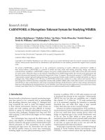
3.2. The dynamic programming matrix
For the pairwise sequence alignment algorithm, the optimal
scores S(i, j) are tabulated in a two-dimensional matrix, with
i
= 0 M and j = 0 N, as shown in Figure 5.Aswe
calculate the solutions to subproblems S(i, j), their optimal
alignment scores are stored in the appropriate (i, j)cellof
the matrix.
3.3. A bottom-up calculation to get the optimal score
the dynamic programming matrix S(i, j) is laid out, it is easy
to fill it in a bottom-up way, from the smallest problems to
progressively bigger problems. We know the boundary con-
ditions in the leftmost column and the topmost row (i.e.,
S(0, 0)
= 0; S(i,0) = γ
∗
i;andS(0, j) = γ
∗
j). For example,
the optimum alignment of the first i residues of sequence x to
Sequence y
j
iSequence x
01 01 0
0
0
1
0
0
−2 −4 −6 −8 −10
−2 1 −1 −3 −5 −7
−4 −10 0 −2 −4
−6 −30−1 1 −1
−8 −5 −21−2 2
Optimum alignment score 2:
01 0 1 0
0
− 010
+1
−2 +1 +1 +1
Figure 5: An example of the dynamic progr amming matrix.
Table 2: Result of eye tracking.
Video 1 Video 2 Video 3 Video 4
Total frame # 1763 1544 583 1241
Tracking failure frame # 17 19 6 15
Correct rate 99 % 98.7 % 98.9 % 98.7 %
Average correct rate 98.8 %
nothing in sequence y has only one possible solution w hich
is to align to the gap characters and pay i gap penalties. Once
we have initialized the top row and left column, we can fill
in the rest of the matrix by using the recursive definition of
S(i, j). So we may calculate any cell based on the three adjoin-
ing cells to the upper left (i
− l, j − l), above (i − l, j), and to
the left (i, j
− l) which are already known. We may iterate two
nested loops, i
= l M and j = l N, to fill in the matrix
left to right and top to bottom.
3.4. A trace back to get the optimal alignment
Once we have finished filling the matrix, the score of the op-
timal alignment of the complete sequences is the last score,
that is, S(M, N). We still do not know the optimal alignment;
however, we recover this by a recursive trace back of the ma-
trix. Starting from cell (M, N), we determine which of the
three cases (i.e., (3)) can be applied to record that choice as
part of the alignment, and then follow the appropriate path
for that case back into the previous cell on the optimum path.
We keep doing that, one cell in the optimal path at a time,
until we reach cell (0, 0), at which point, the optimal align-
ment is fully reconstructed. Figure 5 shows an example of
the dynamic programming matrix for two code sequences,
x
= 0010 and y = 01010 (0: closed eye, 1: open eye). The
scores of match, mismatch, and insertion or deletion are +1,
−1, and −2, respectively. The optimum path consists of the
cells marked by red rectangles.
Che Wei-Gang et al. 7
(a)
(b)
Figure 6: (a) Open eyes, and (b) closed eyes detected correctly.
Table 3: Results of eye signal detection.
User #1 User #2 User #3 User #4
Command 1 29/30 25/27 18/18 35/38
Command 2 15/15 13/13 5/7 15/17
Command 3 13/13 15/18 12/13 18/20
Command 4 14/15 10/12 6/7 14/17
Command 5 13/15 16/17 10/11 18/20
Command 6 17/17 14/19 8/8 6/8
Command 7 17/19 17/19 10/12 10/12
Command 8 18/21 18/21 13/13 21/25
Command 9 16/17 8/10 6/8 17/18
Correct rate 95 % 90.7% 90.6% 88%
Average correct rate 90.1 %
4. EXPERIMENT RESULTS
We use a Logitech QuickCam Pro3000 camera to capture the
video sequence of the disable, and the image resolution is
320
× 240. The system is implemented on a PC with Athlon
3.0 GHz CPU with Microsoft Windows XP. The eye-wink
control system can achieve the speed of 13 frames per sec-
ond. We have tested 5131 frames of the videos of four people
under normal indoor lighting conditions. Based on the SVM
for eye detection, the accuracy of the eye detection inside the
correctly detected face region is above 90%. The correct clas-
sification rate of the open and closed eye is also higher than
92%. Figure 6 shows that the SVM-based eye classifier can
correctly identify the open and closed eyes. The SVM classi-
fier works fine under different illumination conditions due
to the intensity normalization of the training images via his-
togram equalization. The face region is separated into the
two parts for the detection of the individual left eye and the
right eye.
Table 2 lists the results of eye tracking applied on four dif-
ferent test videos. “Total frames #” indicates the total num-
ber of frames in each video. “Tracking failure frame #” is the
number of frames in which the eye tracking fails. The eye
tracking fails when the system can not locate the eye accu-
rately, and then it may missidentify the open eye as a closed
eye or vice versa. The correct rate of eye tracking is defined
as
correct rate
=
Total frame # − Tracking failure frame
Total frame #
(4)
Table 2 shows that the proposed system achieves 98% correct
eye identification.
Table 3 shows the results of eye-winks interpretation sys-
tem operating on the test video sequences of four different
users. Our system can interpret nine different commands.
Each command is composed of a sequence of eye winks. For
each command, the correct interpretation rate for a different
user is described in terms of r
1
/r
2
,wherer
2
is the total test
video sequences for the specific command issued by the des-
ignated user, and r
1
indicates the correctly identified video
sequences.
Figure 7 shows our system eye-wink control interface.
The red solid circle indicates that the eyes are open. Similarly,
the green solid circle indicates that the eyes are closed. There
are nine blocks at the right portion. In each block, there is
a binary digit number representing the specific command
code. In the base mode, we design eight categories: medi-
cal treatments, a diet, a TV, a radio, anair conditioner, a fan,
8 EURASIP Journal on Image and Video Processing
(a)
(b)
Figure 7: Program interface. (a) Layer 1 commands. (b) Layer 2
commands for audio.
a lamp, and a telephone. There are two layers in the com-
mand mode, so we can create at most 9
∗
9(81) commands.
Here, we only use 8
∗
8 + 1(65) commands because in each
layer, we have a “Return” command. In Figure 7,weillustrate
layer 1 commands and layer 2 commands.
5. CONCLUSION AND FUTURE WORK
We propose an effective algorithm for eye-wink interpreta-
tion for human-machine interface. By integrating SVM and
dynamic programming, the eye-wink control interpretation
system will enable the severely handicapped people to m a-
nipulate the household appliances by using a sequence of eye
winks. Experimental results have illustrated the encouraging
performance of the current methods in both accuracy and
speed.
REFERENCES
[1] P. W. Hallinan, “Recognizing human eyes,” in Geometric Meth-
ods in Computer Vision, vol. 1570 of Proceedings of SPIE,pp.
214–226, San Diego, Calif, USA, July 1991.
[2] S. Amarnag, R. S. Kumaran, and J. N. Gowdy, “Real time eye
tracking for human computer interfaces,” in Proceedings of the
International Conference on Multimedia and Expo (ICME ’03),
vol. 3, pp. 557–560, Baltimore, Md, USA, July 2003.
[3] Q. Ji and X. Yang, “Real-time eye, gaze, and face pose t rack-
ing for monitoring driver vigilance,” Real-Time Imaging, vol. 8,
no. 5, pp. 357–377, 2002.
[4] P. Smith, M. Shah, and N. da Vitoria Lobo, “Monitoring
head/eye motion for driver alertness with one camera,” in
Proceedings of the 15th International Conference on Pattern
Recognition (ICPR ’00), vol. 4, pp. 636–642, Barcelona, Spain,
September 2000.
[5] T. D’Orazio, M. Leo, P. Spagnolo, and C. Guaragnella, “A neu-
ral system for eye detection in a driver vigilance application,”
in Proceedings of the 7th International IEEE Conference on In-
telligent Transportation Systems (ITS ’04), pp. 320–325, Wash-
ington, DC, USA, October 2004.
[6] K. F. Van Orden, T P. Jung, and S. Makeig, “Combined eye
activity measures accurately estimate changes in sustained vi-
sual task performance,” Biological Psychology,vol.52,no.3,pp.
221–240, 2000.
[7] R. Shaw, E. Crisman, A. Loomis, and Z. Laszewski, “The eye
wink control interface: using the computer to provide the
severely disabled with increased flexibility and comfort,” in
Proceedings of the 3rd Annual IEEE Symposium on Computer-
Based Medical Systems (CBMS ’90), pp. 105–111, Chapel Hill,
NC, USA, June 1990.
[8] L. Gan, B. Cui, and W. Wang, “Driver fatigue detection based
on eye tracking,” in Proceedings of the 6th World Congress on
Intelligent Control and Automation (WCICA ’06), vol. 2, pp.
5341–5344, Dalian, China, June 2006.
[9] A. Haro, M. Flickner, and I. Essa, “Detecting and tracking eyes
by using their physiological properties, dynamics, and appear-
ance,” in Proceedings of the IEEE Conference on Computer Vi-
sion and Pattern Recognition (CVPR ’00), vol. 1, pp. 163–168,
Hilton Head Island, SC, USA, June 2000.
[10] A. Iijima, M. Haida, N. Ishikawa, H. Minamitani, and Y. Shi-
nohara, “Head mounted goggle system with liquid crystal dis-
play for evaluation of eye tracking functions on neurological
disease patients,” in Proceedings of the 25th Annual Interna-
tional Conference of the IEEE Engineering in Medicine and Biol-
og y Society (EMBS ’03), vol. 4, pp. 3225–3228, Cancun, Mex-
ico, September 2003.
[11] I. Fasel, B. Fortenberry, and J. Movellan, “A generative frame-
work for real time object detection and classification,” Com-
puter Vision and Image Understanding, vol. 98, no. 1, pp. 182–
210, 2005.
[12] Z. Zhu and Q. Ji, “Robust real-time eye detection and track-
ing under variable lighting conditions and var ious face orien-
tations,” Computer Vision and Image Understanding, vol. 98,
no. 1, pp. 124–154, 2005.
[13] C. H. Morimoto and M. Flickner, “Real-time multiple face
detection using active illumination,” in Proceedings of the 4th
IEEE International Conference on Automatic Face and Gesture
Recognition (FG ’00), pp. 8–13, Grenoble, France, March 2000.
[14] X. Liu, F. Xu, and K. Fujimura, “Real-time eye detection and
tracking for driver observation under various light condi-
tions,” in Proceedings of the IEEE Intelligent Vehicle Symposium
(IV ’02), vol. 2, pp. 344–351, Versailles, France, June 2002.
[15] D. W. Hansen and A. E. C. Pece, “Eye tracking in the wild,”
Computer Vision and Image Understanding, vol. 98, no. 1,
pp. 155–181, 2005.
[16] D. Chai and K. N. Ngan, “Face segmentation using skin-color
map in videophone applications,” IEEE Transactions on Cir-
cuits and Systems for Video Technology, vol. 9, no. 4, pp. 551–
564, 1999.
[17] D. Chai, S. L. Phung, and A. Bouzerdoum, “Skin color de-
tection for face localization in human-machine communi-
cations,” in Proceedings of the 6th International, Symposium
on Signal Processing and Its Applications (ISSPA ’01), vol. 1,
pp. 343–346, Kuala Lumpur, Malaysia, August 2001.
Che Wei-Gang et al. 9
[18] V. N. Vapnik, The Nature of Statistical Learning Theory,
Springer, New York, NY, USA, 1995.
[19] N. Otsu, “A threshold selection method from gray-level his-
tograms,” IEEE Transcations on Systems, Man, and Cybernetics,
vol. 9, no. 1, pp. 62–66, 1979.