Báo cáo hóa học: " Research Article Compression of Human Motion Animation Using the Reduction of Interjoint Correlation" doc
Bạn đang xem bản rút gọn của tài liệu. Xem và tải ngay bản đầy đủ của tài liệu tại đây (2.02 MB, 15 trang )
Hindawi Publishing Corporation
EURASIP Journal on Image and Video Processing
Volume 2008, Article ID 693427, 15 pages
doi:10.1155/2008/693427
Research Article
Compression of Human Motion Animation Using
the Reduction of Interjoint Correlation
Shiyu Li, Masahiro Okuda, and Shin-ichi Takahashi
Department of Environmental Engi neering, Faculty of Environmental Engineering, The University of Kitakyushu,
Kitakyushu-shi 808-0135, Japan
Correspondence should be addressed to Shiyu Li,
Received 1 February 2007; Revised 14 July 2007; Accepted 23 October 2007
Recommended by Nikos Nikolaidis
We propose two compression methods for the human motion in 3D space, based on the forward and inverse kinematics. In a
motion chain, a movement of each joint is represented by a series of vector signals in 3D space. In general, specific types of joints
such as end effectors often require higher precision than other general types of joints in, for example, CG animation and robot
manipulation. The first method, which combines wavelet transform and forward kinematics, enables users to reconstruct the end
effectors more precisely. Moreover, progressive decoding can be realized. The distortion of parent joint coming from quantization
affects its child joint in turn and is accumulated to the end effector. To address this problem and to control the movement of the
whole body, we propose a prediction method further based on the inverse kinematics. This method achieves efficient compression
with a higher compression ratio and higher quality of the motion data. By comparing with some conventional methods, we
demonstrate the advantage of ours with typical motions.
Copyright © 2008 Shiyu Li et al. This is an open access article distributed under the Creative Commons Attribution License, which
permits unrestricted use, distribution, and reproduction in any medium, provided the original work is properly cited.
1. INTRODUCTION
3D motion capture systems have been widely used in CG
amusement and human motion analysis such as games and
athlete training. To use these human motion capture data
to produce compelling animation, the users need a mo-
tion library to store the existing motion data. Large mo-
tion databases do not accept the uncompressed forms, since
the motion data are often huge. For example, the size of
only a 3-second sample of the skeleton motion capture data
with 200 frames, in a typical motion format, is about 200 KB.
On the other hand, motion data transmission often requires
compactly coded motion [1]. Studying these issues, we be-
lieve the motion compression is essential for all these tasks.
In this paper, we propose two compression methods for
the human motion in 3D space, based on the forward and in-
verse kinematics. Analyzing the human motion signals, such
as walking, dancing, and kicking, we find that these motions
contain mainly low-frequency components and discarding
some small wavelet coefficients will not bring great effects on
the motion. Thus, in the first method, we propose a com-
pression algorithm for motion data which combines wavelet
transform and forward kinematics (FK) to achieve a pro-
gressive motion compression. Due to appearance of distor-
tion caused by the quantization, the error is propagated from
higher to lower levels in a motion chain hierarchy. To reduce
this effect, we compensate the error by a forward kinemat-
ics fashion. The method also gives a hierarchical description
of the motion by virtue of the wavelet transform so that the
progressive encoding/decoding is possible, which is efficient
for motion editing and key framing [2–5].
The second method uses a prediction, based on the in-
verse kinematics (IK). Although this is not a hierarchical cod-
ing, more efficient compression in a sense of accuracy can
be given. This method exploits two redundancies, the cor-
relation between frames and the correlation between joints.
For motion compression, these two should be taken into ac-
count simultaneously. However, few techniques specially ad-
dress them. In our method, the correlation between the joints
is efficiently reduced by the inverse kinematics.
In the general motion formats, the motion of all joints in
a frame is described by three rotation angles with respect to
X, Y,andZ axes. In this paper, we apply a converted format,
which includes two angles of transformation and one angle
2 EURASIP Journal on Image and Video Processing
of orientation for each joint, to be compressed instead of the
three rotation angles. This approach brings the advantages
as the first, to control the position more precisely by assign-
ing more bits than orientation that is less important than the
position in many cases; secondly, to save computation time
and improve the compression efficiency, two angles of trans-
formation are utilized to get a closed form expression of the
Jacobian matrix.
The remainder of the paper is organized as follows. After
areviewofpreviousworkinSection 2, we present the intro-
duction about the transformation from the general motion
format to the converted format in Section 3 and give a brief
description of wavelet-based compression algorithm and us-
ing forward kinematics for data optimization in Section 4.In
Section 5, we explain the inverse kinematics-based compres-
sion algorithm in detail. The motion compression procedure
with a predicting technique is also assigned in this section.
Illustrative motion examples are given in Section 6 to show
the advantage of our approach. In Section 7,weconcludethe
method.
2. BACKGROUND
Many works in computer graphics address the problem of
huge motion data and present compact expression of the mo-
tion [1–3, 6]. These previous methods focus on the reduc-
tion of the number of motion samples. Liu et al. introduced
a system for analyzing and indexing motion databases [7].
Their method reduces the size of the database by selecting
the principal markers and constructing simple models to de-
scribe groups of similar poses. Furthermore, recently, the re-
searchers in motion identification, extracting, analysis, and
classification pay more attention to controlling the motion
signals in low dimensionality [8–10]. Although the need for
compressing the large motion database exists in many fields,
their studies are only located in using key-poses to represent
the action synopsis by a sequence of motions. For a mono-
tone and periodic sample, the key-poses can synopsize the
action well, while they are not sufficient to the complicated
action. In this case, only the compressed representation of
the whole motion fulfills the requirement of the users.
While the motion compression attempts to represent the
whole motion by fewer amounts of data without subsam-
pling, the conventional key framing methods subsample it
and interpolate the key frames smoothly while rendering.
The key framing realizes a compact representation as well.
However, if one applies the key framing to the compression,
some problems arise. First, essentially selected key frames
should not be correlated. It is difficult to compress a lot even
though the number of frames is smaller. Moreover, when the
key frames are regularly sampled, it is difficult to compensate
sudden changes by the interpolation and it often results in
over- and under-shoots. When irregular key frame sampling
is applied (which is much more common in CG), one needs
to encode not only the data but also the time indexes, result-
ing in increase of data. Lim and Thalmann achieve motion
compression by the key-posture extraction of motion data
using the motion curve simplification in [6]. Based on the
method in [6], Etou et al. proposed the use of only five joints
as the important joints and applied the motion curve simpli-
fication method in these selected joints to reduce the dimen-
sionality [2]. Ahmed et al. utilized the wavelet technique to
compress each sample [11]. In [12] Arikan introduced a lossy
compression algorithm. They approximated the short clips
of motion using Bezier curves and clustered principal com-
ponent analysis. To avoid solving the nonlinear problem of
the orientations, they represent the motion by 3 times more
storage (3 virtual marker positions for each frame instead
of 3 joint angles). Obviously, this representation introduces
a problem of space complexity. To reduce the high dimen-
sionality, they group the similar looking clips into clusters
and use PCA in each cluster. This processing brings another
problem of time complexity. For motion compression, one
should take into account (1) the correlation between joints
and (2) the correlation in time domain. In other words, the
level of accuracy should be accordingly changed, depending
on frames and joints such as end effectors which often re-
quire higher precision than other general types of joints due
to motion characters. Most of these conventional methods
[2, 6, 11, 12] focus on the correlation only in time domain.
To solve those two problems, we proposed a compression
algorithm for motion data which combines wavelet trans-
form and forward kinematics. To reduce the distortion in hi-
erarchy chain, we compensate the error by a forward kine-
matics fashion. The method also gives a hierarchical descrip-
tion of the motion by virtue of the wavelet so that progressive
encoding/decoding is possible, which is efficient for motion
editing and key-framing.
However, according to the forward kinematics, in a mo-
tion chain, the distortion of a joint that comes from the
quantization introduces the warp of the position to its child
joint. The distortion of this child joint aff
ects its grand child
joint in turn, and so on. The warp may be accumulated to the
end effector which is usually treated as the most important
joint for some motion feature. To reduce the propagation of
the warp to the end effectors, we have to minimize the errors
between the actual positions and the compressed results in
the lower level of hierarchy. The forward kinematics cannot
address this problem perfectly.
To control the movement of the whole body, it is com-
mon to use the inverse kinematics [13]. It is presumed that
the specified joints, called the end effectors are assigned
in target positions from preceding positions. By position
changes of the end effectors one may get variations of the
motion of the entire body using the inverse kinematics algo-
rithm. Therefore, for most joints, when recovering motion
in a decoder, we only require a series of small modifications
to the corresponding values. The author of [12] realizes the
importance of the end effectors and compresses them sepa-
rately by DCT. Unfortunately, in his paper we cannot find a
solution for exploiting correlation between joints.
A linear prediction has been widely used and successfully
applied in compression of time series data. If we can predict
every next frame, we only need to save the first frame and the
difference between real value and its prediction. The better
the predictions, the more common corrections we can get
and the more bits we can save. The inverse kinematics based
approach solves the above problems efficiently [14].
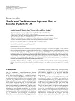
Shiyu Li et al. 3
Root
Terminator
Link
Left limb chain
(thick curve)
End effector
Figure 1: Human figure.
We further present an inverse kinematics based compres-
sion method in this paper. In our work, we improve the cal-
culation for the prediction of next frame by adding the con-
straint of minimizing the acceleration of the motion instead
of minimizing the velocity which is described in [14]. Be-
cause the constraint of minimizing the velocity, which de-
duces the Moore-Penrose pseudoinverse, relates a series of
smallest changes of the rotation angles to a small displace-
ment in the end effector, it is not adapted to the motion com-
pression.
3. PRELIMINARY
3.1. General format
In CG application, a human figure is modeled by a hierar-
chical chain, in which connections between two neighboring
joints are rigid, for example, the joints of a shoulder and an
elbow move, but the distance between them is not changed.
In this framework, the motion data is expressed by a series
of rotations instead of x, y, z coordinates. A motion chain,
which is hierarchically constructed by some linked joints, has
one end that is free to move, which is called an end effector.
The other end of the chain is fixed and called a terminator
(see Figure 1). In Figure 1, a joint defined as an origin of co-
ordinates is called a root. The root may have multiple trees
and the several end effectors. Kinematics based motion data
processing is to handle the motion chains, such as trunk, up-
per limbs and lower limbs.
The motion capture data format, such as BVH format
which is employed in our experiment, typically includes the
position of the root and orientation of other joints [15]. For
the orientation of the joints, the three Euler rotation angles
are adopted rather than the quaternion.
In the motion chain, to calculate the position of a joint we
need to create a rigid transformation matrix by local transla-
tion and rotation information. A rotation matrix R is com-
posed of three Euler rotation matrices with respect to X, Y ,Z
axes [16]. Suppose a rotation order is YXZ,byconcatenat-
ing the Euler rotation matrices, we can get R
= R
Z
·R
X
·R
Y
.
By applying a matrix T which is a homogeneous matrix to
represent both the translation and the rotation by one com-
mon equation, the position of a joint in global coordinate p
G
can be described by
p
G
= T·p
L
,(1)
where p
G
= [
1 P
X
P
Y
P
Z
]
T
, p
L
is the position of this joint in
local coordinate, and p
L
= [
1 P
x
P
y
P
z
]
T
,
T
=
⎡
⎢
⎢
⎢
⎣
1
.
.
.0
··· ···
l
.
.
. R
⎤
⎥
⎥
⎥
⎦
,(2)
and l is a translation vector [
1 l
x
l
y
l
z
]
T
. Once the local trans-
formation of a joint is created, it will be concatenated with
the transformation of its parent, then its grand parent, and
so on. The position of this joint in world coordinate can be
obtained by
p
world
= T
root
·T
grandparent
·T
parent
·T
child
·p
child
. (3)
3.2. Converted angle format
We assume the motion chains are expressed by the rigid
transform except for the root joint with the position, x, y,z,
in the world coordinate. We first convert the three Euler ro-
tation angles to two rotations and one orientation. The two
rotations perfectly specify the position in 3D space, and the
rest represents its orientation. Since in most applications the
position is more important than the orientation, by assigning
more bits during the compression one can have a degree of
freedom to reconstruct the position more precisely than the
orientation. This format also realizes the scalability of data.
That is, if motions are described only by the positions (i.e.,
orientation is not included) like data captured from most
of the motion capture equipments or a user in the decoder
needs only the positions (i.e., orientation is not required),
it is possible to transmit the two φ and ϕ of the three an-
gles, which saves much more information to send. Moreover,
as we will explain later, this converted format gives a closed
form expression of Jacobian matrix in the inverse kinemat-
ics algorithm which is the partial derivative of the function
about the position and the rotation angles of the joint with
respect to a set of angles and saves computation time.
Suppose the length of a link connecting a child joint and
a parent joint is r, and the two positions are related by a ro-
tation R
ZXY
:
p
parent
= R
ZXY
·p
child
,(4)
p
parent
= [
p
Xparent
p
Yparent
p
Zparent
]
T
is represented by two an-
gles:
p
Xparent
= r·sin φ·cos ϕ,
p
Yparent
= r·sin φ·sin ϕ,
p
Zparent
= r·cos φ ,
(5)
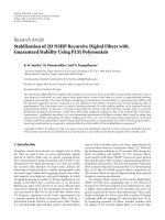
4 EURASIP Journal on Image and Video Processing
Z
Y
X
r
p
Xparent
p
Zparent
p
Yparent
ϕ
φ
Figure 2: Direction of the spherical angles in a 3D coordinate sys-
tem.
where φ and ϕ can substitute for three Euler angles to be
compressed in the IK algorithm in Section 3.TheFigure 2
shows the direction of these spherical angles of a 3D coordi-
nation system.
To represent the motion, the positions of the joints in
world coordinate can be represented by two angles φ and ϕ
sufficiently in (5), and these positions can represent the skele-
ton motion instead of the orientation of the joints. However,
to apply our compression algorithm to more general CG an-
imations, we further need a parameter, the orientation angle
ψ, to retrieve the three Euler angle since a joint may present
different orientation in a same position in the world coordi-
nate. We can calculate the orientation angle ψ by a standard
matrix of rotation around an arbitrary axis [17]. Suppose A
is the matrix that rotates by angle ψ about the axis u is
A
=
⎡
⎢
⎢
⎢
⎢
⎣
tx
2
r
+ ctx
r
y
r
+ sz
r
tx
r
z
r
−sy
r
0
tx
r
y
r
−sz
r
ty
2
r
+ cty
r
z
r
+ sx
r
0
tx
r
z
r
+ sy
r
ty
r
z
r
−sx
r
tz
2
r
+ c 0
0001
⎤
⎥
⎥
⎥
⎥
⎦
,(6)
where c
= cos(ψ), s = sin(ψ), t = 1 −cos(ψ)andx
r
, y
r
and
z
r
are the components of a unit vector on the axis u though
the origin and p
parent
. In our case, u = [p
Xparent
, p
Yparent
,
p
Zparent
]holds.SupposeR
cross
is the rotation matrix which
is built by current position p
child
and target position p
parent
.
Combine (4), (5), and (6), then we can easily get
R
ZXY
= A·R
cross
. (7)
Note that φ, ϕ,andψ at each frame are data to be encoded.
Since the variance of ψ is usually small, this angle format of-
ten improves compression efficiency in practice.
The three Euler angles may exhibit discontinuity when
the angles are limited in [0, 2
∗
π]. This is easily addressed by
the conventional phase unwrapping technique. We actually
use “unwrap” in the MATLAB library. In the decoder, after
reconstructing the rotation matrix Rzxy, the orientation an-
gle can be retrieved by limiting three Euler angles in a quad-
rant and the absolute value of them between [0, 2
∗
π].
4. WAVELET CODING ALGORITHM
4.1. General wavelet coding for motion
Analyzing the human motion signal, such as walking, danc-
ing and kicking, we find these motions contain mainly low
frequency components and discarding some small wavelet
coefficients will not introduce the large effects on the mo-
tion. In [11], the author also gives a report about it. However,
using a constant quantization for all motion signals may in-
troduce visible error such that motion appears dithering or
other unnatural manner. Thus, variable stepsizes in quan-
tization are required to encode motion signals of different
joints.
As applied in image compression and other computer
graphics applications [18, 19], the general wavelet-based
compression steps are given as follows. In an encoder phase,
we decompose a signal into a sequence of wavelet coefficients
W, then quantize them with multiple stepsizes to convert W
to a sequence Q in quantization, finally apply entropy coding
to compress Q into a sequence E. In decoder phase, the con-
trary operations are performed. Therefore, the motion data
are quantized adaptively, so that the decoder receives a com-
pressed data without visible artifacts.
In our compression algorithm, we perform the 9/7 tap
wavelet transform, and our aim is to compress curves of all
the joints represented by series of rotations in all frames.
4.2. ROI coding of motion
In motion compression, to keep some special characteristics,
we have to consider two constraints which are also specified
in motion editing [4, 5]. The one is used to describe an artic-
ulated figure [13], such as the elbow and knee joints should
not bend backward, that is, the rotation angles about these
typesofjointsshouldbeinsomeranges.Thesecondcon-
straint is used to guarantee that the end effector is placed at
a particular position in some frames. For example, consider-
ing a motion in which a human puts a box on a desk, in last
some frames, the box should be precisely put on the desk. In
this paper, we call these frames “constraint frames.” The con-
straint frames are derived automatically from the interaction
between the figure and environment or specified by user. In
the encoding steps, it is useful that the user can adaptively
compress the joints. For example, smaller quantization step-
size is used for important joints. The important joints, which
are located more precisely than others, are called “constraint
joints” in this paper. This can be done by region-of-interest
(ROI) coding.
To make this ROI coding possible, we apply the max shift
method [18]. The max shift method is used in image com-
pression for defining the ROI which is encoded and trans-
mitted with better quality than the rest of the image and de-
coded first before any background information [20]. Before
the quantization, the constraint frames are scaled up. Thus,
the frames are quantized by a different stepsize to implement
different compression ratio as motion behavior. In motion
reconstruction, the signals are scaled down after dequantiza-
tion. The decoder can distinguish these scaled signals from
Shiyu Li et al. 5
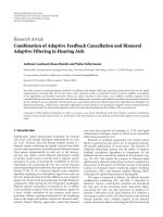
A
B
B
C
C
End effector
(a) Distortion of B and C
A
B
B
C
C
C
End effector
(b) Rotate B
C
to find optimal C
Figure 3
general signals. More accurate frames will be gained and
hence the motion feature can be preserved.
4.3. Forward kinematics for data optimization
ROI-based approach preserves a large amount of features of
the motion. However, the lossy compression for rotation an-
gles produces some quantization error. In Figure 3(a), the
position of B is warped to B
andinturnC is warped to C
.
Finally, the warp is accumulated to the end effector.
To reduce the propagation of the warp, we have to min-
imize the error of position between C and C
. Utilizing the
quantized position of the root joint and a correct position of
the child joint, we can obtain an optimal position of the child
joint instead of its warped one (Figure 3(b)).
Since the length between B
and C
is fixed, suppose this
link is l, rotate the link B
C
with respect to B
to meet the
line B
C, we get an intersection C
.IntriangleΔB
C
C of
Figure 3(b),
B
C
+ C
C>B
C, we can easily educe C
C>
C
C.ThatmeansC
is closer to C than C
, that is, E
C
<E
C
,
where E
C
denotes the error of distance between C
and C,
while E
C
denotes the error of distance between C
and C. C
is clearly the optimal position. Calculate R
new
corresponding
to C
. R
new
indicates the rotation of C
about B
and can be
calculated by p
C
and p
C
. p
C
is original position of C in its
parent coordinate with origin B and p
C
is optimal position
of C
in its parent coordinate with origin B
.
Then in each motion chain, the optimal rotation angles
of a child joint can be gotten by warped position of its parent
sequentially and encoded instead of the original data [21].
A motion data compression algorithm is shown in Fig-
ure 4.
5. INVERSE KINEMATICS BASED ALGORITHM
5.1. Inverse kinematics
According to the forward kinematics, in a motion chain, the
transformation of a parent joint causes a change of its child
Dequantization hierar-
chically
Max shift for
constraint frames
(scale down)
Max shift for
constraint frames
(scale up)
Hierarchical
quantization
Entropy decoding
Input bits
Output : joint iInput : joint i
Inverse wavelet
transform:
c
0
, w
0
, w
1
, , w
j−1
, c
j−1
Wave le t transf orm:
c
0
, w
0
, w
1
, , w
j−1
, c
j−1
Convert to Euler angle
format
Convert to two angle
format
Data com-
pensation for
joint i +1
Inverse
operation
(decoder)
Entropy coding
Output bits
Encoder
Decoder
Figure 4: Adaptive algorithm for optimization-based motion data
compression.
θ
1
θ
2
θ
3
P
End effector
Terminator
P
end
= f (θ)
(a) Forward kinematics
θ
1
θ
2
θ
3
P
End effector
Terminator
θ
= f
−1
(P
end
)
(b) Inverse kinematics
Figure 5
joint position. The change of this child joint in turn affects
its grand child joint, and so on. Finally the changes are ac-
cumulated to the end effector. Motion is inherited down the
hierarchy from the parents to the children (Figure 5(a)). For
simplicity, we discuss two-dimensional case. In the frame n,
the position of the end effector P
n
in two dimensional can be
determined:
P
n
= f (θ
n
), (8)
where θ
n
is composed of all angles (θ
1
, θ
2
, θ
3
, , θ
Nj
)for
each joint in frame n.
In the inverse kinematics, motion is inherited up the hi-
erarchy, from the extremities to the root (Figure 5(b)). The
role of the IK algorithm is to automatically work out how
each joint in a chain should be transformed so that the end
6 EURASIP Journal on Image and Video Processing
(1) The 3 Euler angles θ
x
, θ
y
, θ
z
of each
joint in each frame are inputted
(2) Convert θ
x
, θ
y
, θ
z
into φ and ϕ by (4)and
(5)calculatetheψ using (6)
(3) Calculate the increment Δp of the
position of the end effector by (16)
(4) Calculate the Jacobian marix J using the angles
φ and ϕ of last frame by (19)
(5) Get the pseudoinverse J
∗
of J by (14)
(6) Obtain the angle change of φ and ϕ by (15)
(7) Calculate the angle change of the ψ by simply
finding the difference of the two connective
frames
(8) Apply quantization in the data obtained in the
step 3, 6 and 7 respectively using different
stepsize
(9) Perform entropy coding for the data
obtained in step 8
(10) Send the compressed data to the decoder
Algorithm 1: IK Algorithm.
effector can reach the goal. To find the set of the changes of
the angles which satisfy a given displacement of the positions
of the end effectors, we need to solve
θ
n
= f
−1
(P
n
). (9)
However, this inverse is, in most cases, difficult to solve.
Instead of this, Jacobian-based method is utilized [22–24].
Equation (8) is written in differential form:
˙
P
n
= J
˙
θ
n
, (10)
J is the Jacobian matrix of the displacement of the position
of the end effector
˙
P
n
with respect to the changes of the joint
angles
˙
θ
n
and
J
≡
∂P
n
∂θ
n
. (11)
To get the desire
˙
θ
n
,onehastosolve
˙
θ
n
= J
−1
˙
P
n
. (12)
Since the natural human body motion typically is repre-
sented over 30 degrees of freedom (DOF) which is larger than
rank of J, the set of (12) are underdetermined. To solve this,
some constraints are needed. Meanwhile for motion com-
pression, the constraint used to make adjustments of the
joint angles must be considered to match the motion char-
acters. Traditionally, one minimizes the norm of the velocity
of the joint angl
˙
θ
n
under the constraint J
˙
θ
n
−
˙
P
n
= 0.
Then, (12)iswrittenby
˙
θ
n
= J
∗
˙
P
n
, (13)
where
J
∗
= J
T
(JJ
T
)
−1
(14)
Compressed
angles of
previous
frame
Position
calculation
Simple
prediction
Entropy
coding
Entropy
coding
Quantization
DecodingDecoding
Quantization
Converted format
End
effectors
General
other
joints
Prediction
by IK
Orientation
calculation
Simple
prediction
Calculate
prediction
error
Com-
pressed
position
˙
p
θ
0
D
D
ψ
ψ
δ
(a) Encoder
Entropy
decoding
Entropy
decoding
Position
calculation
Dequantization
Dequantization
Angle
conversion
Bits of
end
effectors
Bits of
general
other joints
Orientation
angle
retrieval
Convert all joints to original angle format
Prediction
by IK
Converted
two angles
Compressed
angles of
previous frame
δ
D
ψ
θ
0
˙
p
(b) Decoder
Figure 6: IK algorithm-based compression flow chart.
and it is called Moore-Penrose pseudoinverse. Equation (13)
linearly relates the displacement of the end effectors to the
change of joint angles. However, it relates a series of smallest
change of the rotation angles to a small displacement in the
end effectors. Obviously it is not desirable for motion com-
pression. It is possible to consider another solution than this
Shiyu Li et al. 7
constraint. In this paper, we employ the constraint of mini-
mizing the norm of the differential acceleration
˙
θ
n
−
˙
θ
n−1
2
and get the solution in our prediction algorithm:
˙
θ
n
= θ
0
+ J
∗
(
˙
P
n
−Jθ
0
), (15)
where θ
0
= k
˙
θ
n−1
, k is the parameter that determines the
weighting between the solution and the error. It is clear that
this method leads to satisfying the natural motion charac-
ter better than traditional minimizing the velocities of the
joint angles. When ΔP
n
, which is a displacement of end ef-
fector from previous position to current position, is given,
the change of each joint can be determined by (13).
Our IK algorithm consists of the following steps.
(1) Calculate the increment Δp of the position of the end
effector from the frame i
−1, p
i−1
to the frame i, p
i
:
Δp
= p
i
− p
i−1
. (16)
(2) Calculate Jacobian matrix J(φ
1
, ϕ
1
, φ
2
, ϕ
2
, φ
3
, ϕ
3
, ,
φ
Nj
, ϕ
Nj
) using the angles of last frame (φ
1
, ϕ
1
, φ
2
, ϕ
2
,
φ
3
, ϕ
3
, , φ
Nj
, ϕ
Nj
), where φ
j
and ϕ
j
are the two an-
gles in (5). Since
p
i
(x, y, z) =
⎡
⎢
⎣
f
1
(φ, ϕ)
f
2
(φ, ϕ)
f
3
(φ)
⎤
⎥
⎦
, (17)
where,
f
1
(φ, ϕ) =
n
j=1
L
j
·sin(φ
j
)cos(ϕ
j
),
f
2
(φ, ϕ) =
n
j=1
L
j
·sin(φ
j
) sin(ϕ
j
),
f
3
(φ) =
n
j=1
L
j
·cos(φ
j
)
(18)
by (5)andL
j
is the length of link j, then by (10), Δp =
J[
˙
φ
j
˙
ϕ
j
]and
J
=
∂f
1
(φ, ϕ)
∂φ
j
∂f
1
(φ, ϕ)
∂ϕ
j
,
∂f
2
(φ, ϕ)
∂φ
j
∂f
2
(φ, ϕ)
∂ϕ
j
,
∂f
3
(φ)
∂φ
j
0
,
(19)
where
∂f
1
(φ, ϕ)
∂φ
j
= L
j
cos(φ
j
)cos(ϕ
j
),
∂f
1
(φ, ϕ)
∂ϕ
j
=−L
j
sin(φ
j
) sin(ϕ
j
),
∂f
2
(φ, ϕ)
∂φ
j
= L
j
cos(φ
j
) sin(ϕ
j
),
∂f
2
(φ, ϕ)
∂ϕ
j
= L
j
sin(φ
j
)cos(ϕ
j
),
∂f
3
(φ)
∂φ
j
=−L
j
sin(φ
j
) .
(20)
(3) Get the pseudoinverse of J by (14).
(4) In each motion chain, obtain the changes in frame i
for φ
1
, ϕ
1
, φ
2
, ϕ
2
, , φ
Nj
, ϕ
Nj
by (15).
˙
θ
i
is the change
of the angles in frame i and is given by
˙
θ
i
= k
˙
θ
i−1
+
J
∗
(Δp − J
∗
k
˙
θ
i−1
). We obtain the good results with
k
= 2.
In step (2), if the general format, which is composed of ro-
tation angles about X, Y, Z axes, is applied to calculate the
Jacobian matrix, each element of the Jacobian matrix almost
involves all the related trigonometric functions of the corre-
sponding angles in the motion chain. While in our converted
format, since φ and ϕ are calculated by the product of all the
related rotation matrices from current joint to root joint, us-
ing converted format, the Jacobian J is given in a closed form.
Although two angles format is sufficient to represent the po-
sition of the joints in the world coordinate, the constraints
on the joints generally controlled by the orientation of the
joints. To apply our compression algorithm to more general
CG animations, we further using the parameter ψ that is the
orientation angle and calculated by the standard matrix of
rotation around an arbitrary axis introduced in Section 3.2.
Therefore, initial orientation of the three Euler angles of the
joint is retrieved perfectly.
Finally, the algorithm is stated in Algorithm 1.
5.2. Compression with prediction technique
Considering motion characters, we have to assign more bits
to some special joints such as the end effectors than other
general types of joints. An adaptive quantization approach
preserves features of the motion greatly. To achieve this, the
hierarchical stepsize for different joints can be implemented
in quantization step.
Meanwhile, since the amount of motion data is consider-
able, high compression rate is needed. Prediction based tech-
niques have been widely and successfully applied in compres-
sion of series of data. If we can predict every next frame, we
only have to save the first frame and the difference between
real value and predicting result. The better the predictions,
the more common corrections we can get and the more bits
we can save.
The aforementioned two points characterize our IK com-
pression approach properly when comparing with previous
works. Actually, there are no conventional algorithms that
specialize the constraints in joints, that is, precise reconstruc-
tion of the end effectors, and achieve efficient compression
rate simultaneously.
To predict every next frame, an intuitive method is to uti-
lize the last frame directly. Taking the difference D
i
between
the current frame i and last frames i
− 1 may be one of the
simplest methods. By this method, we can decode current
value θ
i
in decoder using the equation
θ
i
= θ
i−1
+ D
i
. (21)
Generally, compression rate improvement only depends
on stepsizes. We have to explore a better prediction method
that can provide the data closer to θ
i
.
8 EURASIP Journal on Image and Video Processing
0.486 0.775 1.3835 2.2205 3.1083 4.086
Entropy
Wal k
0
5
10
15
20
25
30
35
Error % in position of joints
0.7022 1.3503 2.1621 3.0897 4.0394 6.8813
Entropy
Ballet
0
5
10
15
20
25
30
35
Error % in position of joints
0.4022 0.6503 1.1621 1.5897 2.3964 3.4813
Entropy
Throw
0
5
10
15
20
25
30
35
Error % in position of joints
0.2436 0.3195 0.6589 0.9363 1.1237 1.4822
Entropy
Kick
0
5
10
15
20
25
30
35
40
Error % in position of joints
IKBP
SPBLF
FKBC
IBKF
DWT
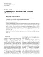
Figure 7: RD curve of the position of the walk, ballet, throw,
and kick motions; IKBP—IK-based prediction method, FKBC—
FK-based compression, SPBLF—simple prediction by last frame,
IBKF—interpolation between the key frames, DWT—discrete
wavelet transform.
0.5374 1.7881 1.921 3.017 3.6424 4.5173
Entropy
Wal k
0
1
2
3
4
5
6
7
8
9
Error % in angle of joints
0.44369 1.0559 1.9509 3.1466 4.3812 5.3861 6.2248
Entropy
Ballet
0
2
4
6
8
10
Error % in angle of joints
0.3295 0.6305 1.3509 1.7183 2.4812 2.9869
Entropy
Throw
0
1
2
3
4
5
6
7
Error % in angle of joints
0.2436 0.5559 0.9565 1.2495 1.4428 1.6827
Entropy
Kick
0
1
2
3
4
5
6
7
8
Error % in angle of joints
IKBP
SPBLF
FKBC
IBKF
DWT
Figure 8:RDcurveoftherotationangleofthewalk,ballet,
throw, and kick motions; IKBP—IK-based prediction method,
FKBC—FK-based compression, SPBLF—simple prediction by last
frame, IBKF—interpolation between the key frames, DWT—
discrete wavelet transform.
Shiyu Li et al. 9
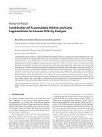
Top: original motion frames
Bottom: compressed motion frames when entropy
= 0.6679
The index of the frames is
1 55 142 184 268 307 392 441 500 600
Wal k mo tion
Top: original motion frames
Bottom: compressed motion frames when entropy
= 1.4227
The index of the frames is
1 121 139 166 220 238 254 313 332 388
Ballet motion
Top: original motion frames
Bottom: compressed motion frames when entropy
= 0.5891
The index of the frames is
1202533394448 6276179
Throw motion
Top: original motion frames
Bottom: compressed motion frames when entropy
= 0.5256
The index of the frames is
1 30 37 51 67 80 96 107 127 147
Kick motion
Figure 9: Series of samplings of the motions.
The inverse kinematics gives a solution exactly. In our
compression method, an encoder calculates the differences
of position of end effectors between two sequential frames.
More bits are assigned to them to keep the precision of the
end effectors in quantization. Then these differences will be
sent to decoder. Next, both in encoder and decoder, using
these differences and the angles in previous frame we can cal-
culate the change of the rotation angle in each joint by IK al-
gorithm approximately. Suppose the difference between the
value predicted by IK and the value in the last frame is D
i
and
θ
ipredict
= θ
i−1
+ D
i
, (22)
D
i
can be calculated by (14) as the
˙
θ
n
. We need transfer δ =
D
i
−D
i
to the decoder which may reconstruct current value
θ
i
by
θ
i
= θ
ipredict
+ δ. (23)
We adopt a prediction for orientation angles of each
joint. Our prediction method is simply done by subtracting
the current frame by the last frame. The IK based compres-
sion procedure with the prediction technique is shown in
Figure 6. In the encoder, the data of the rotation angles of
the end effectors and the other general joints are processed
separately.
Firstly, for the general joints, the change of the rotation
angle in each frame D
i
can be predicted by the compressed
angles
θ
0
of previous frames and the change of the position
˙
p of the end effectors. Here we use the quantized version
θ
0
instead of θ
0
and
˙
p instead of
˙
p to get the same result in the
decoder. After calculating the prediction error δ,weadopt
general quantization and entropy coding to the prediction
error. Meanwhile, we adopt the simple prediction method by
every last frame for the orientation angle ψ of each joint to
get Dψ.
For the end effectors, after the position calculation, we
also adopt the simple prediction method by every last frame.
The quantization and entropy coding are applied into the
simple predicted sequence of the end effectors.
The bits of the end effectors and the other general joints
are sent to the decoder, respectively.
For the bits of the general other joints, the entropy de-
coding and dequantization are implemented as the opposite
processing in the encoder. Using the IK algorithm, we pre-
dict the rotation angles of a current frame by the last decoded
frame
θ
0
, then add the compressed prediction error
δ and the
change of the position of the end effectors
˙
p using
θ
i
=
θ
i−1
+
D
+
δ. (24)
This process is the same as the prediction in the encoder.
For the end effectors, after the entropy decoding and de-
quantization of the bits, we retrieve the position of the end ef-
fector of each frame. Finally, the angle conversion of the end
effectors is added to convert the position of the end effectors
to the rotation angles following the original data format.
6. EXPERIMENTAL RESULTS
In our experiment, we adopted one of the most well-known
format of the human motion, the BVH file format [15, 25].
The BVH file has two parts, a header section which describes
any number of skeleton hierarchies and the initial pose of the
skeleton by translational offsets of children segments from
their parent, and a data section which contains the position
of the root joint and the rotation information of motion of
10 EURASIP Journal on Image and Video Processing
Table 1: Error of position of each joint in a limb chain for walking motion. This table records almost the same entropy of different methods
for compression ratio and the error of the positions of several joints for the quality of the compressed motion correspondingly. In the walking
motion, the left shoulder chain includes 4 joints (left shoulder, left humerus, left radius, and left hand).
Method Entropy
Compression ratio%
Error of the position
Root joint Child joint Grand child joint End effector
left shoulder left humerus left radius left hand
IKBP 0.7144
4.81381 0.4985 0.6238 0.9506 2.1912
SPBLF 0.7269
4.89805 1.6457 2.7175 6.4688 6.3385
FKBC 0.7350
4.95263 3.2423 7.6778 16.009 12.066
IBKF 0.7233
4.87379 >100 >100 >100 >100
DWT 0.7296
4.91625 13.709 28.270 40.623 37.992
IKBP 1.3821
9.31297 0.3576 0.5779 0.7809 1.1068
SPBLF 1.3673
9.21325 0.8872 1.5062 4.8276 4.6992
FKBC 1.3834
9.32173 0.8286 1.3859 1.7912 3.2002
IBKF 1.4056
9.47132 24.459 20.725 26.814 31.092
DWT 1.3850
9.33251 1.1968 1.6492 2.8112 3.4743
IKBP 2.1971
14.8046 0.0613 0.1005 0.1048 0.1616
SPBLF 2.2147
14.9232 1.2701 1.8213 1.0853 1.4703
FKBC 2.2205
14.9623 0.1057 0.1396 0.1376 0.1808
IBKF 2.3724
15.9858 13.021 16.758 14.668 13.227
DWT 2.2181
14.9461 0.1658 0.2417 0.2814 0.3500
IKBP 3.0171
20.3300 0.0521 0.054 0.0649 0.0831
SPBLF 3.1294
21.0867 0.5823 0.8639 0.8143 0.9136
FKBC 3.1083
20.9446 0.0622 0.0653 0.0697 0.0851
IBKF 3.1114
20.9654 4.8487 6.3667 6.8840 7.1055
DWT 3.0573
20.6009 0.0654 0.0714 0.0698 0.0856
IKBP 4.0977
27.6114 0.0237 0.0441 0.0648 0.0726
SPBLF 4.0860
27.5326 0.5423 0.6663 0.6373 0.6093
FKBC 4.0860
27.5326 0.0612 0.0628 0.0662 0.0736
IBKF 4.4625
30.0695 1.5934 2.0052 2.1053 2.4268
DWT 4.1962
28.2751 0.0634 0.0697 0.0677 0.0741
all joints in each frame. In the BVH format, the motion is
described by a series of the three orientation matrices with
respect to y, x, z axes. We convert them to the two angles φ
and ϕ by (5) to represent the position and the orientation ψ,
and then compress them using prediction method.
To evaluate the efficiency, we calculate the error of the
position of joint i of the compressed motion comparing with
the original one by
E
position
(i) =
1
N
f
N
f
j=1
P
i
oj
−P
i
cj
2
(25)
and the error of all joints in all frames by
E
position
=
1
N
j
N
j
i=1
E
position
(i), (26)
where P
i
oj
and P
i
cj
are the 3D positions of joint i in frame
j of original and compressed motions, respectively in world
coordinate. And N
f
is the number of frames, while N
j
is the
number of total joints.
We also calculate the error of three orientation angles of
joint i of the compressed motion comparing with the original
one by
E
angle
(i) =
1
N
f
N
f
j=1
O
i
oj
−O
i
cj
2
(27)
and the error of all joints in all frames by:
E
angle
=
1
N
j
N
j
i=1
E
angle
(i), (28)
where O
i
oj
and O
i
cj
are orientation angles of joint i in frame j
of original and compressed motions, respectively, and N
f
is
the number of frames, while N
j
is the number of total joints.
Note that the three orientation angles of our method are φ, ϕ
and ψ, while the original format consists of three angles with
respect to X, Y , Z axes.
We compare the proposed FK-based compression
(FKBC) and IK based prediction (IKBP) method with other
Shiyu Li et al. 11
Table 2: Error of angle of each joint in a limb chain for walking motion. This table records almost the same entropy of different methods
for compression ratio and the error of the orientation angles of several joints for the quality of the compressed motion correspondingly. In
the walking motion, the left shoulder chain includes 4 joints (left shoulder, left humerus, left radius, and left hand).
Method Entropy
Compression ratio%
Error of the angle
Root joint Child joint Grand child joint End effector
left shoulder left humerus left radius left hand
IKBP 0.5374
3.62115 0.9531 1.1785 0.4022 1.3495
SPBLF 0.5421
3.65282 0.9572 1.1932 0.8255 2.0165
FKBC 0.5539
3.73233 0.9585 1.1967 1.4382 2.9845
IBKF 0.4862
3.27615 34.530 53.226 >100 >100
DWT 0.5336
3.59554 0.9550 1.1717 1.4839 2.2946
IKBP 1.7881
12.0487 0.9530 1.1780 0.4015 1.3490
SPBLF 1.7938
12.0871 0.9568 1.1931 0.5984 2.0154
FKBC 1.7653
11.8950 0.9539 1.1826 0.4606 2.0059
IBKF 1.7804
11.9968 9.557 10.620 19.830 30.80
DWT 1.7671
11.9072 0.9542 1.1792 0.4093 2.0041
IKBP 1.9210
12.9442 0.9530 1.1757 0.4015 1.3483
SPBLF 2.0423
13.7615 0.9557 1.1878 0.5832 2.0151
FKBC 1.9756
13.3121 0.9537 1.1785 0.4534 2.0012
IBKF 2.1027
14.1685 2.2900 10.211 7.8120 30.410
DWT 2.0167
13.5891 0.9539 1.1789 0.4049 1.9998
IKBP 3.6424
24.5435 0.9529 1.1679 0.4009 1.3480
SPBLF 3.6982
24.9195 0.9537 1.1821 0.4439 2.0085
FKBC 3.6733
24.7517 0.9532 1.1781 0.4217 2.0002
IBKF 3.6081
24.3123 1.9200 3.2180 2.0250 7.2390
DWT 3.6729
24.7490 0.9529 1.1778 0.4015 1.9902
IKBP 4.5173
30.4388 0.9528 1.1650 0.3145 1.3483
SPBLF 4.5628
30.7454 0.9529 1.1776 0.4013 1.9961
FKBC 4.6805
31.5385 0.9529 1.1779 0.4014 1.9839
IBKF 4.4625
30.0696 0.8800 1.4900 0.9800 4.2000
DWT 4.5819
30.8741 0.9529 1.1772 0.3978 1.9837
three methods, the simple prediction by last frame (SPBLF)
based on (21)inSection 5, the interpolation between the key
frames (IBKF) and the motion compression technique us-
ing the discrete wavelet transform (DWT) appearing in [11].
(The wavelet transform and interpolations are implemented
by Matlab software which is trustworthy implementation.) In
IBKF based compression method we apply the Piecewise Cu-
bic Hermite (PCH) interpolation into the key frames which
are obtained by curve simplification in [6], while in DWT
method we adopt the 9/7 wavelet transform to compression
the motion data. We give the RD curves of four motions
in Figure 7.Thex-axis represents the summation of the en-
tropies of the three angles obtained by those five methods,
respectively.
The entropy coding is widely used to estimate the bit rate
of the coded stream, which gives theoretically minimal bit
rate. The entropy of a random variable X,whichisdefined
as H(X)
=−
x∈Ax
f
X
(x)log
2
f
X
(x) can be interpreted as
the average amount of information conveyed by the outcome
of the random variable X. A
x
is known as the alphabet ele-
ments. f
X
(x) is the probability of the outcome X = x.Inour
experiment, since we use the same Arithmetic coding in all
methods, the entropy values the compression ratio of each
method.
In Figure 7, the results of the five methods including the
proposed methods are shown. The proposed algorithm IKBP
can get the more common corrections and save more bits
than the general algorithm. The variance of the error of the
joint position calculated by IKBP method is smaller than the
results by FKBC, SPBLF, and IBKF methods. It demonstrates
that our proposed algorithm IKBP can get the more common
corrections and save more bits than the general algorithm.
For the curves generated by the IBKF method, we change
the number of the key frames which are obtained by the IBKF
method introduced in [2] to get the different compressed
form of the motion data. Since the error of the position of
the walking motion by IBKF is more than 100 when the en-
tropy is smaller than 1.0 and the position of the ballet motion
by the IBKF is more than 50 when entropy is smaller than 1.5,
we abridge these large values of the error to give an observ-
able comparison in the range from 0 to 35. Same processing
is used in other two motions.
12 EURASIP Journal on Image and Video Processing
Table 3: Error of position of each joint in a limb chain for ballet motion. This table records almost the same entropy of different methods for
compression ratio and the error of the position of the joints for the quality of the compressed motion correspondingly. In the ballet motion,
the left shoulder chain includes 3 joints (left shoulder, left elbow, and left wrist).
Method Entropy Compression ratio%
Error of the position
Root joint left shoulder Parent joint left elbow Child joint left wrist
IKBP 0.5054 6.2786 0.5621 1.1875 1.2351
SPBLF 0.5016 6.2314 1.0252 11.6327 17.4201
FKBC 0.5321 6.6103 2.6686 8.9683 13.7177
IBKF 0.5000 6.2115 >100 >100 >100
DWT 0.5391 6.6973 3.1183 8.7364 13.9129
IKBP 1.0624 13.198 0.2159 0.4591 0.5628
SPBLF 1.0545 13.100 1.0191 11.5586 15.9806
FKBC 1.0298 12.793 1.9960 4.6145 6.8852
IBKF 1.0264 12.751 21.1268 21.8202 23.1181
DWT 1.0297 12.792 2.0151 4.7956 7.2744
IKBP 2.1256 26.406 0.1376 0.3624 0.3563
SPBLF 2.0841 25.891 1.0025 4.8103 5.2754
FKBC 2.0821 25.866 0.2623 0.5816 0.9040
IBKF 2.0064 24.925 9.1289 9.7715 10.5541
DWT 2.1014 26.106 0.4755 0.8853 1.2702
IKBP 4.2955 53.363 0.0633 0.0606 0.0649
SPBLF 4.3064 53.499 0.6863 1.4141 1.7705
FKBC 4.3674 54.256 0.0600 0.0691 0.0785
IBKF 4.3231 53.706 1.4282 1.5323 1.7680
DWT 4.3067 53.502 0.1267 0.2102 0.2908
IKBP 6.9143 85.897 0.0575 0.0541 0.0583
SPBLF 6.9749 86.650 0.5604 1.1152 1.5466
FKBC 6.9160 85.918 0.0551 0.0561 0.0573
IBKF 6.9896 86.832 0.2412 0.2856 0.3554
DWT 6.9365 86.173 0.0932 0.1046 0.1519
At low bit rates, FKBC is inferior to SPBLF, FKBC gains
better compression in low compression rate. Note that FKBC
is a hierarchical coding scheme and a progressive decoding is
possible by virtue of the wavelet, while IKBP and SPBLF do
not have this property.
Figure 8 shows the RD curves about the error of the three
orientation angles. The x-axis represents the summation of
the entropies of three angles. For the curve generated by the
IBKF method, since the error of the rotation angle of the
walking motion by the IBKF is more than 100 when the en-
tropy is smaller than 3, we also abridge the data of the large
error by IBKF to give a comparison in the error range from 0
to 9.
We also present the error of positions and the orienta-
tions of each joint in a limb chain corresponding to the dif-
ferent entropy value of the walk motion in Tables 1 and 2 and
the ballet motion in Tables 3 and 4,respectively,todemon-
strate the advantage of our approach. Since different motion
has different hierarchy skeleton, in the walk motion the left
shoulder chain includes 4 joints (left shoulder, left humerus,
left radius, and left hand), while in the ballet motion, the
same motion chain has 3 joints (left shoulder, left elbow and
left wrist). When the entropy is smaller than 1, the error of
the positions of some joints by IBKF is larger than 100 and
the recovered motion is totally distorted. In the same com-
pressing ratio, the proposed algorithm IKBP produces small
error of the positions in these joints than the general algo-
rithms.
Figure 9 shows series of samples of the original mo-
tions and the decoded one by IKBP method correspondingly.
These series of samplings present a period of the motion. In
walk motion, when entropy is larger than 1.1206 it is diffi-
cult to discovery the difference between the original motion
and the decoded one. We also show the results of other three
motions, “ballet,” “throw” and “kick.” Tab le 5 gives the de-
scription of these four motions.
Finally, we compare the compression and decompres-
sion times in Tabl e 6 . The specification of the hardware of
PC is that CPU is Pentium(R) 4 3.00 GHz and Memory is
0.99 GB. We record the encoding and decoding times of one
frame of the walk motion with 580 frames. Although our
proposed method appears about 0.3 milliseconds lower than
SPBLF method and about 0.18 milliseconds lower than IBKF
method in compressing a frame, considering the compres-
sion ratio and quality of the recovered motion our algorithm
is much better than IBKF and better than other methods.
Shiyu Li et al. 13
Table 4: Error of angle of each joint in a limb chain for ballet motion. This table records almost the same entropy of different methods for
compression ratio and the error of the orientation angle of the joints for the quality of the compressed motion correspondingly. In the ballet
motion, the left shoulder chain includes 3 joints (left shoulder, left elbow and left wrist).
Method Entropy Compression ratio%
Error of the position
Root joint left shoulder Parent joint left elbow Child joint left wrist
IKBP 0.5054 6.2786 0.2648 0.6546 2.5389
SPBLF 0.5016 6.2314 1.4050 1.5067 6.4131
FKBC 0.5321 6.6103 0.6517 1.0528 2.3071
IBKF 0.5000 6.2115 45.4032 63.6985 66.9011
DWT 0.5391 6.6973 1.4340 1.7459 2.8383
IKBP 1.0624 13.198 0.2319 0.5896 1.5122
SPBLF 1.0545 13.100 1.3362 1.4687 5.5020
FKBC 1.0298 12.793 0.2685 0.6239 1.7313
IBKF 1.0264 12.751 30.2023 49.6792 66.2010
DWT 1.0297 12.792 0.2723 0.6732 1.9386
IKBP 2.1256 26.406 0.2302 0.5428 0.6538
SPBLF 2.0841 25.891 0.2816 0.9719 1.5518
FKBC 2.0821 25.866 0.2307 0.5430 0.6586
IBKF 2.0064 24.925 10.8476 33.8133 49.7030
DWT 2.1014 26.106 0.2391 0.5847 0.7053
IKBP 4.2955 53.363 0.2259 0.5378 0.3868
SPBLF 4.3064 53.499 0.2296 0.5620 0.4168
FKBC 4.3674 54.256 0.2267 0.5371 0.3483
IBKF 4.3231 53.706 3.4238 8.8972 20.4645
DWT 4.3067 53.502 0.2271 0.5384 0.3831
IKBP 6.9143 85.897 0.2257 0.5372 0.3504
SPBLF 6.9749 86.650 0.2257 0.5405 0.3483
FKBC 6.9160 85.918 0.2267 0.5371 0.3476
IBKF 6.9896 86.832 2.9320 4.1791 8.5528
DWT 6.9365 86.173 0.2265 0.5371 0.3479
Table 5: Four original motion data.
Data size Number of joints Sampling rate Number of frames
Walk
324 k 23 0.00833 (s) 580
Ballet
183 k 20 0.0400 (s) 388
Throw
70 k 17 0.033333 (s) 179
Kick
56 k 19 0.033333 (s) 147
Table 6: Compression and decompression times for one frame.
Encoding Decoding
IKBP 1.26 (ms) 1.32 (ms)
SPBLF 0.96 (ms) 1.09 (ms)
FKBC 1.12 (ms) 1.20 (ms)
IBKF 1.08 (ms) 1.20 (ms)
DWT 1.12 (ms) 1.15 (ms)
7. CONCLUSION
The compression of captured motion data is an impor-
tant issue in motion storing, retrieval, editting and trans-
mitting. For the motion compression, some specific types
of joints such as end effectors often require higher pre-
cision than other general types of joints in, for exam-
ple, CG animation and robot manipulation. There are
no conventional algorithms specialize the constraints in
joints and achieve efficient compression rate simultaneously.
Using forward kinematics, we implemented a constraint
based compression algorithm for motion data with spe-
cial characteristics which can be indicated by motion be-
havior or specified by user. However, to solve the problem
that the distortion of parent joint coming from quantiza-
tion in turn affects its child joint and is accumulated to
the end effector, the forward kinematics cannot work per-
fectly.
14 EURASIP Journal on Image and Video Processing
Inverse kinematics is a common approach to control the
movement of the whole body. The position of end effector
can be specified in a target position from preceding position.
By the changes of the position of the end effectors we may
get variations of the motion of the entire body. The inverse
kinematics, on the other hand, supports a prediction-based
compression. To predict motion in decoder, we only save the
first frame and a series of small differences between real value
and prediction gotten by the variations of the positions of the
end effectors. Therefore, it can solve the problems of specific
joints and achieve efficient compression of the motion data.
We applied the FK based compression and IK based com-
pression in our reduced two-angle format. Some experimen-
tal results of example motions demonstrate the advantage of
our methods compared with conventional methods.
ACKNOWLEDGMENTS
This work was partly supported by a Grant-in-Aid for Young
Sciences (no. 14750305) of Japan Society for the Promotion
of Science, fund from MEXT via Kitakyushu innovative clus-
ter project, and Kitakyushu IT Open Laboratory of National
Institute of Information and Communications Technology
(NiCT).
REFERENCES
[1] A. Bruderlin and L. Williams, “Motion signal processing,” in
Proceedings of the 22nd Annual Conference on Computer Graph-
ics and Interactive Techniques (SIGGRAPH ’95), pp. 97–104,
Los Angeles, Calif, USA, August 1995.
[2] H. Etou, Y. Okada, and K. Niijima, “Feature preserving mo-
tion compression based on hierarchical curve simplification,”
in Proceedings of IEEE International Conference on Multimedia
and Expo (ICME ’04), vol. 2, pp. 1435–1438, Taipei, Taiwan,
June 2004.
[3] S. Li, M. Okuda, and S I. Takahashi, “Embedded key-frame
extraction for CG animation by frame decimation,” in Pro-
ceedings of IEEE International Conference on Multimedia and
Expo (ICME ’05), pp. 1404–1407, Amsterdam, The Nether-
lands, July 2005.
[4] J Lee and S. Y. Shin, “A hierarchical approach to interactive
motion editing for human-like figures,” in Proceedings of the
26th Annual Conference on Computer Graphics and Interac-
tive techniques (SIGGRAPH ’99), pp. 39–48, Los Angeles, Calif,
USA, August 1999.
[5] M. Gleicher, “Motion editing with spacetime constraints,” in
Proceedings of the Symposium on Interactive 3D Graphics,pp.
139–148, Providence, RI, USA, April 1997.
[6] I. S. Lim and D. Thalmann, “Key-posture extraction out of hu-
man motion data by curve simplification,” in Proceedings of the
23rd Annual International Conference of the IEEE Engineering
in Medicine and Biology Society (EMBC ’01), vol. 2, pp. 1167–
1169, Istanbul, Turkey, October 2001.
[7] G.Liu,J.Zhang,W.Wang,andL.McMillan,“Asystemforan-
alyzing and indexing human-motion databases,” in Proceed-
ings of the ACM International Conference on Management of
Data (SIGMOD ’05), pp. 924–926, Baltimore, Md, USA, June
2005.
[8] J. Assa, Y. Caspi, and D. Cohen-Or, “Action synopsis: pose
selection and illustration,” ACM Transactions on Graphics,
vol. 24, no. 3, pp. 667–676, 2005.
[9] A. Safonova, J. K. Hodgins, and N. S. Pollard, “Synthesiz-
ing physically realistic human motion in low-dimensional,
behavior-specific spaces,” ACM Transactions on Graphics,
vol. 23, no. 3, pp. 514–521, 2004.
[10] J. Chai and J. K. Hodgins, “Performance animation from low-
dimensional control signals,” in Proceedings of International
Conference on Computer Graphics and Interactive Techniques
(SIGGRAPH ’05), pp. 686–696, Los Angeles, Calif, USA, July-
August 2005.
[11] A. Ahmed, A. Hilton, and F. Mokhtarian, “Adaptive compres-
sion of human animation data,” in Proceedings of the Annual
Conference of the European Associat ion for Computer Graphics
(Eurographics ’02), Saarbr
¨
ucken, Germany, September 2002.
[12] O. Arikan, “Compression of motion capture databases,” in
Proceedings of the 33rd International Conference and Exhibi-
tion on Computer Graphics and Interactive Techniques (SIG-
GRAPH ’06), pp. 890–897, Boston, Mass, USA, July-August
2006.
[13] M. Naganand and F. Stuart, “Specialised constraints for an in-
verse kinematics animation system applied to articulated fig-
ures,” in Proceedings of the Annual Conference of the European
Association for Computer Graphics (Eurographics ’98), pp. 215–
223, Leeds, UK, 1998.
[14] S. Li, M. Okuda, and S. Takahashi, “Kinematics based mo-
tion compression for human figure animation,” in Proceed-
ings of the 30th IEEE International Conference on Acoustics,
Speech, and Signal Processing (ICASSP ’05), vol. 2, pp. 1077–
1080, Philadelphia, Pa, USA, March 2005.
[15] J. Lander, “Working with motion capture formats,” Darwin
3D, LLC, January 1998.
[16] M. Z. Vladimir, Kinematics of Human Motion, Human Kinet-
ics, Champaign, Ill, USA, 1998.
[17] A. S. Glassner, Graphics Gems, Academic Press, Boston, Mass,
USA, 1990.
[18] C. Christopoulos, J. Askelof, and M. Larsson, “Efficient region
of interest coding techniques in the upcomingJPEG2000 still
image coding standard,” in Proceedings of IEEE International
Conference on Image Processing (ICIP ’00), vol. 2, pp. 41–44,
Vancouver, BC, Canada, September 2000.
[19] A. Secker and D. Taubman, “Motion-compensated highly scal-
able video compression using anadaptive 3D wavelet trans-
form based on lifting,” in Proceedings of International Con-
ference on Image Processing (ICIP ’01), vol. 2, pp. 1029–1032,
Thessaloniki, Greece, October 2001.
[20] I. Ueno and W. A. Pearlman, “Region-of-interest coding in
volumetric images with shape-adaptive wavelet transform,”
in Image and Video Communications and Processing 2003,
vol. 5022 of Proceedings of SPIE, pp. 1048–1055, Santa Clara,
Calif, USA, January 2003.
[21] S. Li, M. Okuda, and S. Takahashi, “Hierarchical human mo-
tion compression with constraints on frames,” in Proceedings
of the 47th Midwest Symposium on Circuits and Systems (MWS-
CAS ’04), vol. 1, pp. 253–256, Hiroshima, Japan, July 2004.
[22] S. R. Buss, “Introduction to inverse kinematics with jacobian
transpose, pseudoinverse and damped least squares methods,”
April, 2004.
[23] C. H. Huang and C. A. Klein, “Review of pseudoinverse con-
trol for use with kinematically redundant manipulators,” IEEE
TransactiononSystems,ManandCybernetics, vol. 13, no. 2, pp.
245–250, 1983.
Shiyu Li et al. 15
[24] M. Girard and A. A. Maciejewski, “Computational model-
ing for the computer animation of legged figures,” ACM SIG-
GRAPH Computer Graphics, vol. 19, no. 3, pp. 263–270, 1985.
[25] M. Meredith and S. Maddock, “Motion capture file formats
explained,” Tech. Rep. CS-01-11, Department of Computer
Science, University of Sheffielf, Sheffield, UK, 2001.