Báo cáo hóa học: " Research Article A Multiple-Window Video Embedding Transcoder Based on H.264/AVC Standard" ppt
Bạn đang xem bản rút gọn của tài liệu. Xem và tải ngay bản đầy đủ của tài liệu tại đây (1.58 MB, 17 trang )
Hindawi Publishing Corporation
EURASIP Journal on Advances in Signal Processing
Volume 2007, Article ID 13790, 17 pages
doi:10.1155/2007/13790
Research Article
A Multiple-Window Video Embedding Transcoder Based on
H.264/AVC Standard
Chih-Hung Li, Chung-Neng Wang, and Tihao Chiang
Department of Electronics Engineering, National Chiao-Tung University, 1001 Ta-Hsueh Road, Hsinchu 30010, Taiwan
Received 6 September 2006; Accepted 26 April 2007
Recommended by Alex Kot
This paper proposes a low-complexity multiple-window video embedding transcoder (MW-VET) based on H.264/AVC standard
for various applications that require video embedding services including picture-in-picture (PIP), multichannel mosaic, screen-
split, pay-per-view, channel browsing, commercials and logo insertion, and other visual information embedding services. The
MW-VET embeds multiple foreground pictures at macroblock-aligned positions. It improves the transcoding speed with three
block level adaptive techniques including slice group based transcoding (SGT), reduced frame memory transcoder (RFMT), and
syntax level bypassing (SLB). The SGT utilizes prediction from the slice-aligned data partitions in the original bitstreams such
that the transcoder s imply merges the bitstreams by parsing. When the prediction comes from the newly covered area without
slice-group data partitions, the pixels at the affected macroblocks are transcoded with the RFMT based on the concept of partial
reencoding to minimize the number of refined blocks. The RFMT employs motion vector remapping (MVR) and intra mode
switching (IMS) to handle intercoded blocks and intracoded blocks, respectively. The pixels outside the macroblocks that are
affected by newly covered reference frame are transcoded by the SLB. Experimental results show that, as compared to the cascaded
pixel domain transcoder (CPDT) with the highest complexity, our MW-VET can significantly reduce the processing complexity by
25 times and retain the r ate-distortion performance close to the CPDT. At certain bit rates, the MW-VET can achieve up to 1.5 dB
quality improvement in peak signal-to-noise-ratio (PSNR).
Copyright © 2007 Chih-Hung Li et al. This is an open access article distributed under the Creative Commons Attribution License,
which permits unrestricted use, distribution, and reproduction in any medium, provided the or iginal work is properly cited.
1. INTRODUCTION
Video information embedding technique is essential to
several multimedia applications such as picture-in-picture
(PIP), multichannel mosaic, screen-split, pay-per-view,
channel browsing, commercials and logo insertion, and
other visual information embedding services. With the
superior coding p erformance and network friendliness,
H.264/AVC [1] is regarded as a future multimedia standard
for service providers to deliver digital video contents over
local access network (LAN), dig ital subscriber line (DSL),
integrated services digital network (ISDN), and third gen-
eration (3G) mobile systems [2]. Particularly, the next gen-
eration Internet protocol television service (IPTV) could
be realized w ith H.264/AVC over very-high-bit-rate DSL
(VDSL), which can support higher transmission rates up to
52 Mbps [3]. The service with high transmission rate facil-
itates the development of video services with more func-
tionalities and higher interactivity for video over DSL ap-
plications. For video embedding applications, the video em-
bedding transcoder (VET) is essential to deliver multiple-
window video services over one transmission channel.
The VET functionality can be realized at the client side
where multiple sets of tuners and video decoders acquire
video content of multiple channels for one frame. The con-
tent delivery side sends all the bitstreams of selected channels
to the client while the client side reconstructs the pixels with
an array of decoders in parallel and then re-composes the
pixels into single frame in the pixel domain at the receivers.
Each receiver needs N decoders running with a powerful pic-
ture composition tool to tile the varying size pictures from N
channels. Thus, the overall cost is increased as N is increased.
To reduce the cost of the VET service, fast pixel composition
and less memory access can be achieved based on the archi-
tecture design [4–16]. To realize the VET feature at the client
side, the key issues are inefficient bandwidth utilization and
high hardware complexity that hinders the multiple-w indow
embedding applications deployment.
To increase the bandwidth efficiency and reduce hard-
ware complexity, the VET functionality is realized at the
2 EURASIP Journal on Advances in Signal Processing
server/studio side to deliver selected video contents that are
encapsulated as one bitstream. The challenges are to simulta-
neously maintain the best picture quality after transcoding,
to increase the picture insertion flexibility, to minimize the
archival space of bitstreams, and to reduce hardware com-
plexity. To optimize rate-distortion (R-D) performance, the
bits of the newly covered blocks at the background picture
are replaced by the bits of the blocks at the foreground pic-
tures. To increase the flexibility of picture insertion, the fore-
ground pictures are inserted at the macroblock boundaries
of processing units. To minimize the bitstream storage space,
H.264/AVC coding standard is adopted as the target format.
To decrease the hardware complexity, a low-complexity al-
gorithm for composition is needed. Therefore, we proposed
a fast H.264/AVC-based multiple-window VET (MW-VET),
which encapsulates on-the-fly multiple channels of video
content with a set of precompressed bitstreams into one bit-
stream before transmission.
To t ransmit the video contents via the unitary chan-
nel, the MW-VET embeds downsized video frames into an-
other frame with a specified resolution as the foreground ar-
eas. It can provide preview frames or thumbnail frames by
tiling a two-dimensional array of video frames from multi-
ple television channels simultaneously. With the MW-VET,
users can acquire multiple-channel video contents simulta-
neously. Moreover, the MW-VET bitstreams are compliant to
H.264/AVC and it can facilitate the multiple-window video
playback in a way transparent to the decoder at the client
side.
For real-time applications, video transcoding should re-
tain R-D performance with the lowest complexity, minimal
delay, and the smallest memory requirement [17]. Particu-
larly, the MW-VET should maintain good quality after multi-
generation transcoding that may aggravate the quality degra-
dation. An efficient VET transcoder is critical to address the
issue of quality loss. For complexity reduction, existing ap-
proaches [18–21] convert the bitstreams that are of MPEG-2
standard in the transform domain. Application of the exist-
ing transcoding techniques to H.264/AVC is not feasible since
the advanced coding tools including in-the-loop deblocking
filter, directional spatial prediction, and 6-tap subpixel in-
terpolation all operate in the pixel domain. Consequently,
the transform domain techniques h ave higher complexity as
compared to the spatial domain techniques.
To maintain transcoded picture quality and to reduce the
overall complexity, we present three transcoding techniques:
(1) slice-group-based transcoding (SGT), (2) reduced frame
memory transcoding (RFMT), and (3) syntax level bypass-
ing (SLB). The application of each transcoding technique de-
pends on the data partitions of the archived bitstreams and
the paths of error propagation. For slice-aligned data parti-
tions, the SGT that composes the VET bitstreams at the bit-
stream level c an provide the highest throughput. For region-
aligned data partitions, the RFMT efficiently refines the pre-
diction mismatch and increases throughput while maintain-
ing better R-D performance. For the blocks that are not af-
fected by the drift error, the SLB de-multiplexes and multi-
plexes the bitstreams into a VET bitstream at the bitstream
level. As the foreground bitstreams are encoded as full res-
olution, a downsizing transcoding [22–24] is needed prior
to the VET transcoding. The spatial resolution adaptation
transcoders have been widely investigated in the literatures
and are not studied herein.
Our experimental results show that the MW-VET ar-
chitecture significantly reduces processing complexity by 25
times with similar or even higher R-D performance as com-
pared to the conventional cascaded pixel domain transcoder
(CPDT). The CPDT cascades several decoders and an en-
coder for video embedding transcoding. It offers drift free
performance with the highest computational cost. With the
fast transcoding techniques, the MW-VET can achieve up
to 1.5 dB quality improvement in peak signal-to-noise ratio
(PSNR).
The rest of this paper is organized as follows: Section 2
describes the issues for the video embedding transcoding.
Section 3 reviews the related works and Section 4 describes
our H.264/AVC-based MW-VET. Section 5 shows the simu-
lation results and Section 6 gives the conclusion.
2. PROBLEM STATEMENT
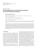
Transcoding process could be viewed as the modification
process of incoming residue according to the changes in the
prediction. As shown in Figure 1(a), the output of transcod-
ing is represented by
R
n
= Q
HT
r
n
= Q
HT
r
n
+Pred
1
y
n
− Pred
2
y
n
,
(1)
where the symbols HT and Q indicate an integer transfor-
mation and quantization, respectively. The symbols
r
n
and
r
n
denote the residue before and after the transcoding. The
symbols Pred
1
(y
n
)andPred
2
(y
n
) represent the predictions
from the reference data
y
n
and y
n
, respectively. In this paper,
we use the symbol “bar” above the variables to denote the re-
constructed values after decoding and the symbol “prime” to
denote the refined values after transcoding. The suffixofeach
variable represents the index of block. The process to embed
the foreground videos onto the background can incur drift
error in the prediction loop since the reference frames at the
decoder and the encoder are not synchronized.
When the predictions before and after the transcoding
are identical, Figure 1(a) can be simplified to Figure 1(b).
The quantized data
r
n
has no further quantization distortion
with the same quantization step. Thus, the transcoded bit-
stream has almost identical R-D performance with the origi-
nal bitstream as represented in:
P
d
· P
e
· r
n
= IHT
IQ
Q
HT
r
n
=
r
n
,(2)
where the symbol P
e
denotes the encoding process from the
pixel domain to the transform domain. The symbol P
d
de-
notes the decoding process from the transform domain back
to the pixel domain. The symbols IHT and DQ mean an
inverse integer transformation and dequantization, respec-
tively.
By (2), the transcoding process in Figure 1(b) can be fur-
ther simplified to that in Figure 1(c), where the data of the
Chih-Hung Li et al. 3
x
n
r
n
−
HT
&Q
Pred
1
(y
n
)
Original
R
n
R
n
DQ &
IHT
r
n
+
x
n
−
r
n
HT
&Q
Pred
1
(y
n
)Pred
2
(y
n
)
ThesameQP
Pred
2
(y
n
)
DQ &
IHT
r
n
x
n
+
Trans cod er
Trans cod ed
(a)
x
n
r
n
−
HT
& Q
Pred
1
(y
n
)
Original
R
n
R
n
DQ &
IHT
r
n
HT
&Q
ThesameQP
Pred
2
(y
n
)
DQ &
IHT
r
n
x
n
+
Trans cod er
Trans cod ed
(b)
x
n
r
n
−
HT
&Q
Pred
1
(y
n
)
Original
R
n
Pred
2
(y
n
)
DQ &
IHT
r
n
x
n
+
Trans cod er
Trans cod ed
(c)
Figure 1: Illustration of a novel tr anscoder : (a) the simplified
transcoding process, (b) the simplified transcoder when the predic-
tion blocks are the same, ( c) the fast transcoder that can bypass the
input transform coefficients.
original bitstreams can be bypassed without any modifica-
tion. It leads to a transcoding scheme with the highest R-D
performance and the lowest complexity.
Video transcoding is intended to maximize R-D perfor-
mance with the lowest complexity. Therefore, the remain-
ing issue is to transcode efficiently the incoming data such
that picture qualit y is maximized with the lowest complexity.
Specifically, the incoming data are refined only when the ref-
erence pixels a re modified to al leviate the propagation error.
To reduce computational cycles and preserve picture quality,
the residue data with identical reference pixels are bypassed.
3. RELATED WORKS ON PICTURE-IN-PICTURE
TRANSCODING
Depending on which domain is used to transcode, the tran-
scoders can be classified as either pixel domain or transform
domain approaches.
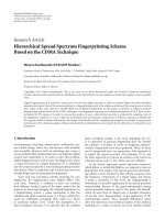
3.1. Cascaded pixel domain transcoder
The cascaded pixel domain transcoder (CPDT) cascades
multiple decoders, a pixel domain composer, and an encoder,
as shown in Figure 2. It decompresses multiple bitstreams,
composes the decoded pixels into one picture, and recom-
BG
bitstream
FG
bitstream 1
FG
bitstream 2
.
.
.
FG
bitstream N
H.264
decoder
H.264
decoder
H.264
decoder
.
.
.
H.264
decoder
PDC
H.264
encoder
PIP
bitstream
PDC:
pixel-domain
composition
Figure 2: Architecture of the CPDT.
presses the picture into a new bitstream. The reencoding pro-
cess of CPDT can avoid drift errors from propagating to the
whole group of pictures.
However, the CPDT suffers from noticeable visual qual-
ity degradation and high complexity. Specifically, the re-
quantization process decreases qualit y of the original bit-
streams. The quality degradation exacerbates especially when
the foreground pictures are inserted at different time using
the CPDT with multiple iterations. In addition, the reencod-
ing makes the significant complexity increase of the CPDT
too costly for real-time video content delivery. The com-
plexity and memory requirement of the CPDT could be re-
duced with fast algorithms that remove inverse transforma-
tion, motion compensation, and motion estimation.
3.2. DCT domain transcoding with motion
vector remapping
The inverse transformation can be eliminated with the dis-
crete cosine transform (DCT) domain inverse motion com-
pensation (IMC) approach proposed by Chang et al. [18–20]
for the MPEG-2 transcoders. The matrix translation manip-
ulations are used to extract a DCT block that is not aligned to
the boundaries of 8
× 8 blocks in the DCT domain. Chang’s
approach could achieve 10% to 30% speedup over the CPDT.
There are other algorithms to speed up the DCT domain
IMC in [25–27].
The motion estimation can be eliminated with motion
vector remapping (MVR) where the new motion vectors are
obtained by examining only two most likely candidate mo-
tion vectors located at the edges outside the foreground pic-
ture. It simplifies the reencoding process with negligible pic-
ture quality degradation.
3.3. DCT domain transcoding with backtracking
A DCT domain transcoder based on a backtracking process
is proposed by Yu and Nahrstedt [21] to further improve the
transcoding throughput. The backtracking process finds the
affected macroblocks (MBs) of the background pictures in
the motion prediction loop. Since only a small percentage of
the MBs at the background are affected, only the damaged
MBs are fixed and the unaffected MBs are bypassed.
4 EURASIP Journal on Advances in Signal Processing
In practice, for most effective backtracking, the future
motion prediction path of each affected MB needs to be an-
alyzed and stored in advance. To construct the motion pre-
diction chains, Chang et al. [18–20] completely reconstructs
all the refined reference frames in the DCT domain for each
group-of-picture (GOP). With the motion prediction chains,
the transcoder decodes minimum number of MBs to render
the correct video contents. The speedup of motion compen-
sation is up to 90% at the cost of the buffering delay of the
transcoder for one GOP period. The impact of the delay on
the real-time applications depends on the length of a GOP in
the original bitstream.
However, the backtracking method has no use for the
H.264/AVC-based transcoder due to the deblocking filter,
the directional spatial prediction, and interpolation filter. In
addition, to track the prediction paths of H.264/AVC bit-
streams, almost 100% of the blocks need decoding, which is
over the 10% reported in [21]. Thus, the expected complex-
ity reduction is limited. Furthermore, it introduces an extra
delay of one GOP period.
In summary, to speed up the CPDT, there are many
fast algorithms to manipulate the incoming bitstreams in
the transform domain. However, this is not the case for the
H.264/AVC standard. To our best knowledge, all the state-of-
the-art transcoding schemes with H.264 as input bitstream
format perform the fast algorithms in the pixel domain [28–
36]. There are se veral reasons to manifest the necessity of
pixel domain manipulation. As shown in the appendix the
pixel domain transcoder actually takes less complexity than
the transform domain transcoder. The detail derivations are
given in the appendix for brevity. In addition, the transfor m
domain manipulation introduces drift because the motion
compensation is based on the filtered pixels which are the
output of the in-the-loop deblocking filter. The fi ltering op-
eration is defined in the pixel domain and cannot be per-
formed in the transform domain due to its nonlinear opera-
tions [28–30]. As a result, the transform domain transcoder
for the H.264/AVC standard typically leads to an unaccept-
able level of error as shown in [ 37]. Therefore, we conclude
that the spatial domain technique is a more realistic approach
for H.264/AVC-based transcoding. To resolve issues of low
computational cost, less drift error, and small memory band-
width, we present an H.264/AVC-based tr anscoder in the
spatial domain.
4. LOW-COMPLEXITY MULTIPLE-WINDOW VIDEO
EMBEDDING TRANSCODER (MW-VET)
For real-time delivery of high quality video bitstreams, our
goal is to build the bitstreams with the picture quality close
to that of the original bitstream using smallest complexity. To
minimize cost and memory requirement a nd retain the best
picture quality, we present a low-complexity multiple win-
dow video embedding transcoder (MW-VET) suitable for
both interactive and noninteractive applications. In Tabl e 1,
we list all the symbol definitions used in the proposed archi-
tectures.
Table 1: Symbol definitions.
Symbol Meaning
CAVLD Content adaptive variable length decoding
CAVLC
Content adaptive variable length coding
LB
Line buffer
FM
Frame memory
DB
Deblocking filter
IP
Intra prediction
MC
Motion compensation
ME
Motion estimation
HT & Q
Integer transform and quantization
DQ & IHT
Dequantization and inverse integer transform
PDC
Pixel domain composition
RDO MD
Rate-distortion optimized mode decision
MUX
Multiplexer (syntax element selector)
4.1. Rationale
To embed foreground pictures as multiple windows to
one background picture, the MW-VET inserts the fore-
ground pictures at MB-aligned positions. To minimize
complexity, it uses several approaches including slice-
group-based transcoding (SGT), reduced-frame-memory
transcoder (RFMT), and syntax level bypassing (SLB) to
adapt the prediction schemes compliant with the H.264/AVC
standard. As the prediction is applied to the slice-aligned data
partitions within the original bitstreams, the SGT merges
the original bitstreams into one bitstream by parsing and
concatenation leading to a fast transcoding. For noninter-
active services, the SGT can provide the highest tr a nscoding
throughput if the original bitstreams are coded with the slice-
aligned data partitions.
When the prediction is applied to the region-aligned
data partitions, the specified pixels at the background pic-
ture are replaced by the pixels of the foreground pictures.
For the pixels in the affected MBs, the RFMT can mini-
mize the total number of refined blocks by partially reencod-
ing only those MBs. The RFMT employs both motion vec-
tor remapping (MVR) for intercoded blocks and intramode
switching (IMS) for intracoded blocks, respectively. The pix-
els within the unaffected MBs are transcoded by the SLB that
passes the syntax elements from the original bitstreams to the
transcoded bitstream.
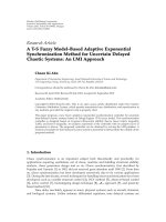
Based on the occurrence of modified reference pixels at
the prediction loop, the MBs are classified into three types:
w-MB, p-MB, and n-MB. As shown in Figure 3, the small
rectangle denotes the foreground picture (FG) and the large
rectangle denotes the background picture (BG). Each small
square within the rectangle represents one MB. The w-MBs
represent the blocks whose reference samples are entirely or
partial ly replaced by the newly inserted pictures. The p-MBs
represent the blocks whose reference pixels are composed of
the pixels at w-MBs. The remaining MBs of the background
pictures are denoted as n-MBs for the unaffected MBs. We
observe that most of the MBs within the processing picture
are p-MBs and only a small percentage of MBs are w-MBs. As
Chih-Hung Li et al. 5
FG
BG
Frame n
− 1
BG
FG
Frame n
FG
BG
Frame n +1
w-MB
p-MB
n-MB
Intraprediction path
Interprediction path
Figure 3: Illustration of the wrong reference problem.
for w-MBs, the coding modes or motion vectors of the orig-
inal bitstream are modified to fix the wrong reference prob-
lem. For the p-MBs, the wrong reference problem is inher-
ited from the w-MBs. Thus, the coding modes and motion
vectors are refined for each p-MB. All n-MBs’ information
in the original bitstream can be bypassed because the predic-
tors before and after transcoding are i dentical.
4.2. Slice-group-based transcoding
The slice-group-based transcoding (SGT) is used when the
prediction within the original bitstream of background pic-
ture uses the slice-aligned data partitions [38]. Based on the
slice-aligned data partitions, the SGT operates at the bit-
stream level to provide the highest throughput with the low-
est complexity. The rationale is that H.264/AVC defines a set
of MBs to the slice group map types according to the adaptive
data partition [1]. The concept of slice group is to separate
the picture into isolated regions to prevent error propagation
from leading error resiliency and random access. Each slice is
regarded as an isolated region as defined in H.264/AVC stan-
dard. For each region, the encoder performs the prediction
and filtering processes without referring to the pixels of the
other regions.
For the video embedding feature using static slice groups,
the large window denotes a background slice and the embed-
ded small windows denote foreground slices. After video em-
bedding transcoding, all the slices are encoded separately at
the slice level and encapsulated to one bitstream at the slice
level. Based on archived H.264/AVC bitstreams with the slice
groups, a VET can replace the syntax elements of MBs in
the foreground slices with the syntax elements of other bit-
streams with identical spatial resolutions. Therefore, all the
syntax elements are directly forwarded as is to the final bit-
stream via an entropy coder. In conclusion, the SGT is effec-
tive for noninteractive applications with multiple static win-
dows.
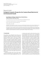
4.3. Reduced frame memory transcoding
Based on the partially reencoding techniques, the initial
RFMT architecture is shown in Figure 4. After decoding all
the bitstreams into pixel domain with multiple H.264/AVC
decoders and composing all the decoded pictures into one
frame by the PDC, the reencoder side only refines the residue
of the affected MBs rather than reencoding all the decoded
pixels as the CPDT architecture. For those unaffected MBs,
the syntax elements are bypassed from each CAVLD and are
sent to the MUX which selects the corresponding syntax el-
ements based on the PIP scenario. Lastly, the CAVLC encap-
sulates all the reused syntax elements and the new syntax el-
ements of refined blocks into the transcoded bitstream.
To increase the throughput, the R-D optimized mode de-
cision and motion vector reestimation within the reencoder
side of Figure 4 are replaced with the int ramode switching
(IMS) and motion vector remapping (MVR) as shown in
Figure 5 [39]. Specifically, the reencoder as enclosed by the
dashed line stores the decoded pixels into the FM. Then, the
MVR and IMS modules retrieve the intra modes and the mo-
tion vectors from the original bitstreams to predict the char-
acteristics of motion and the spatial correlation of the source.
With such information, we examine only a subset of possible
motion vectors and intra modes to speed up the refinement
process. According to the refined motion vectors and coding
modes, the MC and IP modules perform motion compen-
sation and intraprediction from the data in the FM and LB.
The reconstruction loop including HT, Q, DQ, IHT, and DB
generates the reconstructed data of the refined blocks which
are further stored in the FM to avoid the drift during the
transcoding. In conclusion, other than the IMS and MVR
modules all the modules in Figure 5 are the same as those
in Figure 4.
To decouple the dependency between the foreground and
the background, there is an encoding constraint for the fore-
ground bitstream that the unrestricted motion vectors and
the intra-DC modes are not used for the blocks at the first
column or the first row. When the foreground video is from
an archived bitstream or an encoder of live video, the unre-
stricted motion vectors and the intra DC mode can be mod-
ified and the loss of R-D performance is negligible according
to our experiment. Particularly, we rescale the DC coefficient
of the first DC block within an intracoded frame based on the
neighboring reconstructed pixels in the background. Except
the first block, the foreground bitstreams can be multiplexed
directly into the transcoded bitstream.
With the constrained foreground bitstreams, the final ar-
chitecture of the MW-VET is simplified as shown in Figure 6.
The highly efficient MW-VET adopts only the content adap-
tive variable length decoding (CAVLD) for the foreground
bitstreams and uses one shared frame memory for the back-
ground bitstream. At first, two frame memories are dedicated
for the decoder and the reencoder in Figure 5 to store the de-
coded pixels and the reconstructed pixels, respectively. How-
ever, the decoded data of affected blocks are no longer use-
ful and could be replaced with the reconstructed pixels after
the refinement. Therefore, we use a shared frame memory to
buffer the reference pixels for both the decoding and reen-
coding process. Specifically, the operation of the transcoder
begins with the decoding by the CAVLD. The MC and the IP
modules in the left-hand side use the original motion vectors
and intra modes to decode the source bitstream into pixels
stored in the FM and used for the coefficient refinement. On
the other hands, the MC and the IP modules in the right-
hand side use the refined motion vectors and intra modes to
6 EURASIP Journal on Advances in Signal Processing
BG
bitstream
FG
bitstream 1
FG
bitstream 2
FG
bitstream N
.
.
.
CAVLD
CAVLD
CAVLD
CAVLD
H.264 decoder
H.264 decoder
H.264 decoder
H.264 decoder
DQ+IHT+MC+IP+DB+FM+LB
DQ+IHT+MC+IP+DB+FM+LB
DQ+IHT+MC+IP+DB+FM+LB
DQ+IHT+MC+IP+DB+FM+LB
.
.
.
PDC
(Bypass path)
.
.
.
(Bypass path)
(Bypass path)
(Bypass path)
(Partial re-encoding)
ME+RDO
MD+
MC+IP+HT+Q+
IHT+DQ+DB+
FM+LB
MUX
CAVLC
PIP
bitstream
Figure 4: Initial architecture of RFMT with RDO refinement based on the partially reencoding.
BG
bitstream
FG
bitstream 1
FG
bitstream 2
FG
bitstream N
.
.
.
CAVLD
CAVLD
CAVLD
CAVLD
H.264 decoder
H.264 decoder
H.264 decoder
H.264 decoder
DQ+IHT+MC+IP
+DB+FM+LB
DQ+IHT+MC+IP
+DB+FM+LB
DQ+IHT+MC+IP
+DB+FM+LB
DQ+IHT+MC+IP
+DB+FM+LB
.
.
.
PDC
(Bypass path)
.
.
.
(Bypass path)
(Bypass path)
(Bypass path)
(Partial re-encoding with MVR & IMS)
+
+
MVR
IMS
FM
MC
IP
LBDB
HT & Q
DQ & IHT
MUX
CAVLC
PIP
bitstream
Figure 5: Intermediate architecture of RFMT with the MVR and the IMS refinement.
refine the decoded pixels of the affected blocks. In addition
to one shared FM, the transcoding process is the same as that
in Figure 5.
In case the PIP scenario generates the background block
with top and left pixels next to the foreground pictures, our
RFMT needs to decode each foreground bitstreams. Then,
the transcoder switches the mode of this block to DC mode
and computes the new residue according to the reconstructed
values of two foreground pictures. Moreover, if the fore-
ground pictures occupy the whole frame, the feature of chan-
nel preview is realized with the degener ated architecture of
Figure 7. The remaining issues are how the IMS and the MVR
modules deal with the wrong reference problem of back-
ground bitstream. There are two goals: refining the affected
blocks efficiently and deciding the minimal subset of refined
block while retaining the visual quality of transcoded bit-
stream.
4.3.1. Intramode switching
For the intracoded w-MBs, we need to change the in-
tramodes to fix the wrong reference problem since the in-
traprediction is performed in the spatial domain. The neigh-
boring samples of the already encoded blocks are used as
the prediction reference. Thus, when we replace parts of
the background picture with the foreground pixels, the MBs
Chih-Hung Li et al. 7
BG
bitstream
FG
bitstream 1
FG
bitstream 2
FG
bitstream N
.
.
.
CAVLD
CAVLD
CAVLD
CAVLD
.
.
.
Intra
mode
Motion v ectors
DQ & IHT
MC
IP
+
LB
FM
DB
MVR
IMS
LB
IP
MC
(Bypass path)
.
.
.
(Bypass path)
(Bypass path)
(Bypass path)
HT & Q
DQ & IH T
+
+
MUX
CAVLC
PIP
bitstream
Figure 6: Final architecture of RFMT with shared frame memory for the constrained FG bitstreams.
FG bitstream 1
FG bitstream 2
.
.
.
FG bitstream N
CAVLD
CAVLD
.
.
.
CAVLD
MUX
CAVLC
PIP
bitstream
Figure 7: A transcoding scheme for channel preview.
around the borders may have visual artifacts due to the newly
inserted samples. Without drift error correction, the distor-
tion propagates spatially all over the whole frame via the in-
tra prediction process in a raster scanning order. A straight-
forward refinement approach is to apply the R-D optimized
(RDO) mode decision to find the best intra mode from the
available pixels and then reencode new residue.
To reduce complexity we propose an intramode switch-
ing (IMS) technique for the intracoded w-MBs since the
best reference pixels should come from the same region. The
mode switching approach selects the best mode from the
more probable intraprediction modes.
Each 4
× 4 block within a MB could be classified accord-
ing to the intramodes as shown in Figure 8. Similarly, the
mode of the w-block should be refined while the modes of
p-blocks are unchanged. For the w-blocks, the IMS is per-
formed according to the relative position with respect to the
foreground pictures as shown in Figure 9. To speed up the
IMS process, a table lookup method is used to select the new
intramode according to the original intramode and the rel-
FG
BG
w-block
p-block
p-block
Prediction direction
Figure 8: The wrong intrareference problem within a macroblock
depending on the intramodes.
ative position. Tables 2 and 3 enumerate the IMS selection
exhaustively.
With the refined intramode, we compute the new residue
and coded block patterns. It should be noted that only the
reconstructed quantized values are used as the original video
is unavailable. Given that the nth 4
× 4 block is the w-block.
The refinement of the nth 4
× 4blockisdefinedby
r
n
= x
n
− IP
2
x
j
= r
n
+IP
1
x
i
− IP
2
x
j
,(3)
where the symbol
x
n
denotes the decoded pixel. T he sym-
bols IP
1
(x
i
)andIP
2
(x
j
) denote intraprediction from the ref-
erence pixels
x
i
and x
j
by using the original mode, and
the new mode respectively. The symbol
r
n
is the decoded
8 EURASIP Journal on Advances in Signal Processing
FG
BG
1
2345
67
Figure 9: Relative position of each case in intramode switching
method.
Table 2: Cases of Intra4 mode switching.
Case
Corresponding
4
× 4block
Original Mode
∗
Switched Mode
∗
1 Left column of blocks 1, 2, 4, 5, 6, 8 0
2
Topleftofblock 4,5,6 2
3
Top row of blocks 0, 2, 3, 4, 5, 6, 7 1
4
Top right of blocks 3, 7 0
5
Top row of blocks 0, 2, 3, 4, 5, 6, 7 1
6
Left column of blocks 1, 2, 4, 5, 6, 8 0
7
Rightcolumnofblocks 3,7 0
∗
0: Intra 4 × 4 Ve rti cal
1: Intra
4 × 4 Horizontal
2: Intra
4 × 4 DC
3: Intra
4 × 4 Diagonal Down Left
4: Intra
4 × 4 Diagonal Down Right
5: Intra
4 × 4 Ver ti ca l Right
6: Intra
4 × 4 Horizontal Down
7: Intra
4 × 4 Ver ti ca l Left
8: Intra
4 × 4 Horizontal Up
Table 3: Cases of Intra16 mode switching.
Case Original Mode
∗
Switched Mode
∗
1, 6 1, 2, 3 1
2
32
3, 5
0, 2, 3 1
∗
0: Intra 16 × 16 Ve rt ic al
1: Intra
16 × 16 Horizontal
2: Intra
16 × 16 DC
3: Intra
16 × 16 Plane
residue extracted from the source bitstream. Then, the re-
fined residue is requantized and dequantized as
r
n
= P
d
· P
e
· r
n
= P
d
· P
e
·
r
n
+IP
1
x
i
−
IP
2
x
j
=
P
d
· P
e
· r
n
+ P
d
· P
e
· IP
1
x
i
− P
d
· P
e
· IP
2
x
j
=
r
n
+IP
1
x
i
+ e
i
− IP
2
x
j
− e
j
,
(4)
where the symbols e
i
and e
j
are the quantization errors of
IP
1
(x
i
)andIP
2
(x
j
). Lastly, the reconstructed data of the nth
4
× 4 block is shown in as
x
n
= r
n
+IP
2
x
j
=
r
n
+IP
1
x
i
+
e
i
− e
j
=
x
n
+ e
n
,
(5)
where the symbol e
n
denotes the refinement error due to the
additional quantization process.
For the p-blocks, we recalculate the coefficients with the
refined samples of w-blocks. The refinement of w-blocks may
incur drift error that is amplified and propagated to the sub-
sequent p-blocks by the intraprediction process. In order to
alleviate the error propagation, we recalculate the coefficients
of p-blocks based on the new reference samples with the
original intramodes as shown in (6), where we assume the
mth 4
× 4 block is the intracoded p-block that uses the de-
coded data of the nth 4
× 4 block as prediction,
r
m
= x
m
− IP
1
x
n
=
r
m
+IP
1
x
n
−
IP
1
x
n
=
r
m
+IP
1
x
n
− x
n
=
r
m
+IP
1
e
n
.
(6)
Similarly, the refined residue should be requantized and de-
quantized as represented in (7) where the symbol e
m
denotes
the drift error in the mth 4
× 4 block and is identical to the
quantization error of intraprediction of refinement err or e
n
in the nth 4 × 4 block:
x
m
= r
m
+IP
1
x
n
=
P
d
· P
e
· r
m
+ P
d
· P
e
· IP
1
e
n
+IP
1
x
n
=
r
m
+IP
1
e
n
+ e
m
+IP
1
x
n
=
x
m
− IP
1
x
n
+IP
1
x
n
+IP
1
e
n
+ e
m
= x
m
+IP
1
x
n
− x
n
+ e
n
+ e
m
= x
m
+ e
m
.
(7)
Similarly, the next p-block can be derived:
x
m+1
= x
m+1
+ e
m+1
,
e
m+1
= P
d
· P
e
· e
m
− e
m
, m = 1, 2, 3, .
(8)
The generalized projection theory says that consecutive pro-
jections onto two nonconvex sets will reach a trap point be-
yond which future projections do not change the results [40].
After several iterations of error correction, the drift error
cannot be further compensated. Therefore, we only perform
errorcorrectiontothep-blocks within intracoded w-MB
rather than all the subsequent p-blocks. We observe that er-
ror correction for the p-blocks within int racoded w-MB im-
proves the averaged R-D performance up to 1.5 dB. However,
error correction for the intracoded p-MBs has no significant
quality improvement.
4.3.2. Motion vector remapping
The motion information of intercoded w-MBs needs to be
reencoded since the motion vectors of the original bitstreams
point to wrong reference samples after the embedding pro-
cess, since only the motion vector difference is encoded in-
stead of the full scale motion vector. Owing to such pre-
diction dependency, the new foreground video creates the
wrong reference problem.
To solve the wrong reference issue, reencoding the mo-
tion information is necessary for the surrounding MBs near
the borders between foreground and background videos. In
H.264/AVC, the motion vector difference is encoded accord-
ing to the neighboring three motion vectors rather than the
motion vector itself. Hence an identical motion vector pre-
dictor is needed for both encoder and decoder. However, due
Chih-Hung Li et al. 9
to foreground picture insertion, the motion compensation
of background blocks may have wrong reference blocks from
the new foreground pictures. Consequently, the incorrect
motion vectors cause serious prediction error propagated to
subsequent pictures through the motion compensation pro-
cess.
Within the background pictures, the reference pixels
pointed by the motor vector may be lost or changed. For
the MBs with wrong prediction reference, the motion vectors
need to be refined for correct reconstruction at t he receiver.
To provide good tradeoff between the R-D performance and
complexity, only the MBs using the reference blocks across
the picture borders are refined. The refinement process can
be done with motion reestimation, mode decision, and en-
tropy coding. It takes significant complexity to perform ex-
haustive motion reestimation and RDO mode decision for
every MB with wrong prediction reference. Therefore, we use
a motion vector remapping method (MVR) that has been ex-
tensively studied for MPEG-1/2/4 [20–22]. Before applying
the MVR to the intercoded w-MBs, we select the Inter 4
× 4
mode as indicated in Figure 10. The MVR modifies the mo-
tor v ector of every 4
× 4 w-block with a new motion vector
pointing to the nearest of the four boundaries at the fore-
ground picture. With the newly modified motion vectors, the
prediction residue is recomputed and the HT transform is
used to generate the new transform coefficients. Final ly, the
new motion vector and refined transform coefficients of w-
blocks are entropy encoded as the final bitstream. The refine-
ment process of MVR can be represented by (9), where the
symbols MC(
x
i
)andMC(x
j
) denote motion compensation
from the reference pixels
x
i
and x
j
,respectively:
r
n
= x
n
− MC
x
j
=
r
n
+MC
x
i
−
MC
x
j
= r
n
+MC
x
i
− x
j
.
(9)
The refined residue data is requantized and dequantized as
r
n
= P
d
· P
e
· r
n
= P
d
· P
e
·
r
n
+MC
x
i
− x
j
= P
d
· P
e
· r
n
+ P
d
· P
e
· MC
x
i
− x
j
= r
n
+MC
x
i
− x
j
+ e
n
,
(10)
where the symbol e
n
is the quantization error of MC(x
i
− x
j
).
In the transcoded bitstream, the decoded signal of the nth 4
×
4blockisrepresentedin(11) where the symbol e
n
indicates
the refinement error:
x
n
= r
n
+MC
x
j
= r
n
+MC
x
i
− x
j
+ e
n
+MC
x
j
=
x
n
+ e
n
.
(11)
The refinement may occur at the border MBs w ith the skip
mode. Since two neighboring motion vectors are used to in-
fer the motion vector of an MB with the skip mode, the bor-
der MBs with the skip mode may be classified as two kinds of
w-MBs due to the insertion of the foreground blocks. Firstly,
for the w-MBs whose motion vectors that do not refer to a
reference bock covered by the foreground pictures, the skip
mode is changed to Inter 16
× 16 mode to compensate the
mismatch of motion vectors by the motion inference. Sec-
ondly, for the w-MBs wh ose motion vectors point to ref-
erence blocks covered by the foreground pictures, the skip
FG BG
(a)
FG
BG
w-block
(b)
Figure 10: Illustration of motion vector remapping. (a) Original
coding mode and motion vectors. (b) Using Inter 4
× 4modeand
refined motion vectors.
mode is changed to Inter 16 × 16 mode and the motion vec-
tor is refined to new position by the MVR method. Then, the
refined coefficients are computed according to the new pre-
diction.
To fix the wrong subpixel interpolation after inserting the
foreground pictures, the blocks whose motion vectors point
to the wrong subpixel positions are refined. H.264/AVC sup-
ports finer subpixel resolutions such as 1/2, 1/4, and 1/8 pixel.
The subpixel samples do not exist in the reference buffer for
motion prediction. To generate the sub-pixel samples, a 6-
tap interpolation filter is applied to full-pixel samples for
the subpixel location. The sub-pixel samples within 2-pixel
range of picture boundaries are refined to avoid vertical and
horizontal artifacts. The refinement is done by replacing the
wrong subpixel motion vectors with the nearest full-pixel
motion vectors and the new prediction residues are reen-
coded.
4.4. Syntax level bypassing
To minimize the transcoding complexity, the blocks within
intercoded p-MBs and n-MBs are bypassed at the syntax level
after the CAVLD. Since the blocks within p-MBs and n-MBs
are not affected by the picture insertion directly, the syntax
data can be forwarded unchanged to the multiplexer.
As for the intracoded frames, the affected blocks by video
insertion are refined to compensate the drift error. We ob-
serve that the correction of p-blocks within the w-MBs can
significantly improve the quality. In addition, the correction
of intracoded p-MBs might get a bit of quality improvement
with drastically increased complexity.
As for the intercoded frames, we examine the effective-
ness of error compensation by (12). The mth block is inter-
coded p-block and the residue is recomputed with the refined
pixel values by
r
m
= x
m
− MC
x
i
= r
m
+MC
x
i
− MC
x
i
=
r
m
+MC
x
i
− x
i
.
(12)
10 EURASIP Journal on Advances in Signal Processing
Table 4: Corresponding operations of each block type during the
VET transcoding.
Block type Operations
w-MB
Intracoded w-block IMS and CR
∗
Intercoded w-block MVR and CR
∗
Intracoded p-block CR
∗
Intercoded p-block SLB
n-block SLB
p-MB SLB
n-MB
SLB
∗
CR means coefficient recalculation.
Table 5: Encoder parameters for the experiments.
Frame size
QCIF (176 × 144),
CIF (352
× 288),
SD (720
× 480),
HD (1920
× 1088)
Frame rate 30 frames/s
GOP structure
IPPPP P
Total fr am e
100
Intraperiod
15
Reference frame number
1
Motion estimation range
16 for QCIF,
32 for CIF,
64 for SD,
and 176 for HD
Quantization step size 17, 21, 25, 29, 33, 37
Similarly, the transcoded data can b e represented by (13)
where the refinement error of the w-block is propagated to
the next p-block:
x
m
= r
m
+MC
x
i
=
P
d
· P
e
· r
m
+ P
d
· P
e
· MC
x
i
− x
i
+MC
x
i
=
r
m
+MC
x
i
=
x
m
− MC
x
i
+MC
x
i
=
x
m
+MC
x
i
− x
i
.
(13)
Let us assume the refinement of w-block performs well and
the term of MC(
x
i
− x
i
) is smaller than the quantization step
size, it means that the quantization of MC(
x
i
− x
i
)becomes
zero. If our assumption is valid, the term P
d
·P
e
·MC(x
i
− x
i
)
in (13) can be removed. Thus, the drift compensation of in-
tercoded p-block has no quality improvement despite ex-
tra computations. In terms of complexity reduction, we by-
pass all the transfor m coefficients of p-MB and n-MB to the
transcoded bitstream.
In summary, the proposed MW-VET deals with each type
of block efficiently according to Table 4. In addition, the par-
tially reencoding method can preserve picture quality. For
the applications requiring multigeneration transcoding, the
deterioration caused by successive decoding and reencoding
of the signals can be eliminated with the reuse of the cod-
ing information from the original bitstreams. As the motion
10 20 30 40 50 60 70 80 90 100
Frame number
0
20
40
60
80
Percentage ( %)
w-MB
p-MB
w-block
p-block
Figure 11: Percentage of the macroblock types and t he block types
during the VET transcoding.
compensation with multiple reference frames is applied, the
proposed algorithm is still valid. Specifically, it first classifies
the type of each block (i.e., n-block, p-block, and w-block
according to Figure 3). The classification is based on whether
the reference block is covered by foreground pictures and it
does not matter what reference picture is chosen. In other
words, the wrong reference problem with multiple reference
frame feature is an extension of Figure 3. Then, the afore-
mentioned MVR and SLB processes are applied to each type
of intercoded block.
5. EXPERIMENT RESULTS
The R-D performance and execution time are compared
based on the transcoding methods, test sequences, and
picture insertion scenarios. For a fair comparison, all the
transcoding methods have been implemented based on
H.264/AVC reference software of version JM9.4. In addition,
all the transcoders are built using Visual. NET compiler on
a desktop with Windows XP, Intel P4 3.2 GHz, and 2 Giga
bytes DRAM. To further speed up the H.264/AVC based
transcoding, the source code of the reference CAVLD mod-
ule is optimized using a table lookup technique [41]. In the
simulations, the test sequences are preencoded with the test
conditions as shown in Ta ble 5. The notation for each new
transcoded bitstream is “background
foreground x y,” where
x and y are the coordinates of the foreground picture. The
values of x and y need to be on the MB boundaries within the
background picture. To evaluate the picture quality of each
reconstructed sequence, the two original source sequences
are combined to be the reference video source for peak-
signal-to-noise ratio (PSNR) computation.
The percentage of each MB type and each 4
×4blocktype
is shown in Figure 11. In general, the p-MBs occupy 30% to
80% of MBs and the percentage of the w-MBs is less than
15%. In addition, the w-blocks occupy only 5% of the 4
× 4
blocks. Bypassing all the p-blocks that are 95% of blocks ac-
celerates the transcoding process as shown in Table 6. On the
average, as compared to the CPDT, the MW-VET can achieve
25 times of speedup with improved picture quality.
Tabl e 7 lists the PSNR comparison to show the effective-
ness of error correction for different kinds of blocks. The
Chih-Hung Li et al. 11
Table 6: Improvement of execution time and quality as compared
to CPDT.
(1)
VET combination Speed-up
ratio
PSNR gain of
Luma component
BG
(2)
FG
(3)
& location
Stefan Mobile 1 1 25 +1.72 dB
Tab le
Carphone 1 1 28 +1.56 dB
Stefan
Mobile 1 1
28 + 1.18 d B
Foreman 33 1
News 1 20
Coastguard 33 20
Tab le
M&D 1 1
25 + 1.15 d B
Stefan 33 1
Carphone 1 20
News 33 20
(1)
Intel P4 3.2 G, 2 GB SDRAM, Windows XP, and Visual. NET
compiler.
(2)
All are in SD resolution.
(3)
All are in QCIF resolution.
Table 7: Effectiveness of error correction for different kinds of p-
blocks.
Methods PSNR (dB)
Golden 43.73
CPDT
42.02
RFMT w/o EC
41.18
RFMT with EC for the p-blocks
in intra-coded w-MBs
43.16
RFMT with EC for all intracoded p-blocks 43.33
RFMT with EC for all intercoded p-blocks
43.14
golden method is not a transcoding scheme. T he R-D curves
of golden method are obtained from encoding the original
picture-in-picture source sequences. The inclusion of the R-
D curves of golden method is to highlight the upper bound
of a transcoder. The error correction of p-blocks in the intra-
coded w-MBs can obtain a significant gain in picture qual-
ity. Ho wever, the error correction for other p-blocks almost
has no quality improvement while the complexity increases
dramatically. Therefore, the results verify our derivations in
Section 4.
The R-D per formance of different approaches at various
bit rates and different VET scenarios are compared. We em-
bedded one foreground picture into one background picture
at different positions in Figures 12 and 13. The performance
of RFMT is better than that of CPDT. At medium and high
bit rates, the RFMT can offer up to 1.5 dB improvement in
PSNR. Even through the mode and motion vectors obtained
by our IMS and MVR is not always the optimal solution, the
simulation results show that our IMS and MVR approaches
provide a solution close to the optimal case. In the compar-
ison, we have plotted the R-D curves named as RFMT
RDO
to show the optimal R-D performance when the part ial reen-
0 5 10 15 20 25 30
Bit rate (Mbits/s)
28
30
32
34
36
38
40
42
44
PSNR of Y (dB )
Golden
CPDT
RFMT RDO
RFMT
IMS MVR
(a) Table SD Carphone QCIF 1 1
0 5 10 15 20 25 30
Bit rate (Mbits/s)
28
30
32
34
36
38
40
42
44
PSNR of Y (dB )
Golden
CPDT
RFMT RDO
RFMT
IMS MVR
(b) Table SD Carphone QCIF 33 20
Figure 12: Rate-distortion performance of the luminance compo-
nent by one foreground embedding for Table
SD Carphone QCIF.
coding is performed under RDO mode decision and motion
vector reestimation. It could be observed that the R-D per-
formance of RFMT with IMS and MVR is very close to that
of RFMT
RDO.
Figure 14 shows the R-D curve of transcoding bitstreams
that embed four foreground pictures onto one background
picture at the same time. As compared with the one-
foreground VET scenarios, the performance has a little
degradation because that the ratio of w-blocks and p-blocks
increases. Figure 15 shows the performance of multigenera-
tion transcoding that embeds one foreground picture to the
background picture every generation. Our MW-VET can re-
tain the R-D performance while the CPDT degrades every
generation. Thus, the proposed MW-VET is robust for the
multigeneration transcoding.
12 EURASIP Journal on Advances in Signal Processing
0 5 10 15 20 25 30
Bit rate (Mbits/s)
26
28
30
32
34
36
38
40
42
44
PSNR of Y (dB )
Golden
CPDT
RFMT RDO
RFMT
IMS MVR
(a) Mobile SD Foreman QCIF 1 1
0 5 10 15 20 25 30
Bit rate (Mbits/s)
26
28
30
32
34
36
38
40
42
44
PSNR of Y (dB )
Golden
CPDT
RFMT RDO
RFMT
IMS MVR
(b) Mobile SD Foreman QCIF 33 20
Figure 13: Rate-distortion performance of the luminance compo-
nent by one foreground embedding for Mobile
SD Foreman QCIF.
6. CONCLUSIONS
In this paper, we present an efficient multiple-window video
embedding transcoder (MW-VET) to embed the multiple
foreground videos into one background video. The pic-
tures are inserted at the MB-aligned positions to retain high
flexibility. To minimize complexity with negligible quality
loss, the MW-VET uses three novel approaches including
slice group-based transcoding (SGT), reduced frame mem-
ory transcoding (RFMT), and syntax level bypassing (SLB).
These approaches are used based on the H.264/AVC coding
standard compliant prediction schemes.
As the prediction is applied to the slice-aligned data par-
titions within the original bitst reams, the SGT parses and
0 5 10 15 20 25
Bit rate (Mbits/s)
26
28
30
32
34
36
38
40
42
44
PSNR of Y (dB )
Golden
CPDT
RFMT RDO
RFMT
IMS MVR
(a) Mobile SD M&D QCIF 1 1 Stefan QCIF 33 1 Carphone
QCIF 1 20 News QCIF 33 20
0 5 10 15 20 25
Bit rate (Mbits/s)
28
30
32
34
36
38
40
42
44
PSNR of Y (dB )
Golden
CPDT
RFMT RDO
RFMT
IMS MVR
(b) Table SD M&D QCIF 1 1 Stefan QCIF 33 1 Carphone QCIF
1 20 News QCIF 33 20
Figure 14: Rate-distortion performance of the luminance compo-
nent by four foreg rounds embedding.
merges the bitstreams directly. When the prediction is ap-
plied to the region-aligned data partitions, the MBs with
wrong prediction reference are processed with the RFMT
that partially reencodes the blocks to minimize the num-
ber of refined blocks. To handle intercoded and intracoded
blocks that suffer from the wrong reference problem, the
RFMT employs motion vector remapping (MVR), and in-
tramode switching (IMS), respectively. The unaffected MBs
are handled by the SLB in terms of transcoding throughput
and picture quality.
Our results show that the MW-VET as compared to the
cascaded pixel domain transcoder (CPDT) can significantly
reduce the processing complexity by 25 times with similar
or higher R-D performance. In addition, the MW-VET can
Chih-Hung Li et al. 13
0 5 10 15 20 25
Bit rate (Mbits/s)
26
28
30
32
34
36
38
40
42
44
PSNR of Y (dB )
Golden
CPDT
RFMT RDO
RFMT
IMS MVR
(a) Mobile SD M&D QCIF 1 1 Stefan QCIF 33 1 Carphone QCIF
1 20 News QCIF 33 20
0 5 10 15 20 25
Bit rate (Mbits/s)
28
30
32
34
36
38
40
42
44
PSNR of Y (dB )
Golden
CPDT
RFMT RDO
RFMT
IMS MVR
(b) Table SD M&D QCIF 1 1 Stefan QCIF 33 1 Carphone QCIF
1 20 News QCIF 33 20
Figure 15: Rate-distortion performance of the luminance com-
ponent by four foregrounds embedding and multi-generation
transcoding.
achieve up to 1.5 dB quality improvement in PSNR. Based
on the MW-VET, the quality improvement over the CPDT is
significant for multigeneration transcoding.
APPENDICES
A. WHY TRANSFORM DOMAIN APPROACHES
ARE INEFFICIENT FOR H.264/AVC-BASED
TRANSCODING
In this appendix, we will show that it is inefficient to de-
velop a transcoder in the transform domain as commonly
proposed for previous standards such as MPEG-1/2/4. There
are several reasons to support such a claim.
(1) In H.264/AVC, the transformation and quantization
processes are so optimized that traverse back to the
pixel domain is not as expensive as before.
(2) The intraprediction and deblocking filter introduce
stronger spatial domain error propagation although
they are effective to exploit the spatial redundancy.
(3) The IMC becomes inefficient when the motion com-
pensation uses quarter-pixel resolution combined with
6-tap interpolation.
The following text will describe the detailed study to support
such a claim.
A.1. Integer transform with quantization scaling
The transformation used in H.264/AVC is an integrated
transform with quantization scaling, which means the scal-
ing multiplication is merged with the quantization. The in-
teger transform with quantization scaling is performed with
simple integer operations such as shifting and addition,
which indicates no rounding mismatch between the encoder
and the decoder. The relationship between the pixel values at
the encoder and the decoder can be represented by
IHT
DQ
Q
HT(x)
=
x,(A.1)
where x and
x mean the original data and the decoded data
respectively. However, the data after de-quantization is not
the original HT coefficients:
DQ
Q
HT(x)
= HT(x). (A.2)
In order to obtain the transform coefficients at the transcoder
side, an inverse operation of quantization is needed. The in-
verse quantization of HT coefficients is derived as follows.
The fol lowing shows the quantization of HT coefficients Y
i, j
:
Z
i, j
=
Y
i, j
× MF
i, j
+ f
S
1
,
with S
1
= 15 +
QP
6
, f =
2
S
1
3
or
2
S
1
6
.
(A.3)
The following shows that the data after the dequantization is
different from the original H T coefficients:
W
i, j
=
Z
i, j
× V
i, j
S
2
=
Y
i, j
• MF
i, j
+ f
S
1
•
V
i, j
S
2
= Y
i, j
with S
2
=
QP
6
.
(A.4)
The symbols MF
i, j
and V
i, j
are multiplication and rescal-
ing factors, respectively, as defined in H.264/AVC standard.
To obtain the HT coefficients, the dequantization process
shouldbereplacedbyconvertingquantizedcoefficients to
dequantized HT coefficients. The process is computed as
Y
i, j
=
Y
i, j
S
1
MF
i· j
. (A.5)
However , (A.5) requires a division operation with higher
complexity and additional rounding error.
14 EURASIP Journal on Advances in Signal Processing
A.2. Directional intra prediction
The intraprediction as defined in the spatial domain poses
challenges to the transform domain transcoding. To imple-
ment intraprediction in the transform domain significantly
increases complexity because the HT transform is not or-
thogonal, which means the transpose is not equal to the in-
verse for HT transform as represented in below:
HT
⎛
⎜
⎜
⎜
⎜
⎝
⎡
⎢
⎢
⎢
⎢
⎣
××××
××××
××××
ABCD
⎤
⎥
⎥
⎥
⎥
⎦
⎞
⎟
⎟
⎟
⎟
⎠
=
⎛
⎜
⎜
⎜
⎜
⎝
C
f
⎡
⎢
⎢
⎢
⎢
⎣
××××
××××
××××
ABCD
⎤
⎥
⎥
⎥
⎥
⎦
C
T
f
⎞
⎟
⎟
⎟
⎟
⎠
=
⎛
⎜
⎜
⎜
⎜
⎝
C
f
⎡
⎢
⎢
⎢
⎢
⎣
××××
××××
××××
ABCD
⎤
⎥
⎥
⎥
⎥
⎦
C
−1
f
⎞
⎟
⎟
⎟
⎟
⎠
.
(A.6)
The detailed operations of HT domain intraprediction could
be found in [42]. As compared to the pixel domain intrapre-
diction, the computation increases especially in the number
of multiplication as listed in Ta ble 8.
A.3. In-the-loop deblocking filtering
The de-blocking filter defined in the spatial domain intro-
duces mismatch error during HT domain transcoding. Par-
ticularly, the deblocked pixels stored in the reference frame
memory are used for motion compensation. Thus, mismatch
error will propagate to the next frames via motion compen-
sation until the subsequent intracoded frame or slices at the
decoder. To prevent the mismatch error, implementing the
de-blocking filter in the HT domain is required. However,
this kind of implementation increases the complexity and
memory requirement.
A.4. Subpixel interpolation
The complexity of HT domain IMC increases due to the 6-
tap interpolator defined in H.264/AVC. Detailed derivations
are given in the following. A 4
×4 motion-compensated block
can be represented as the summation of four blocks in the
spatial domain where
B
pred(4×4) full pel
=
4
k=1
V
k(4×4)
B
k
H
k(4×4)
,
V
1(4×4)
= V
2(4×4)
=
0 I
h
00
,
H
1(4×4)
= H
3(4×4)
=
00
I
w
0
,
V
3(4×4)
= V
4(4×4)
=
00
I
4−h
0
,
H
2(4×4)
= H
4(4×4)
=
0 I
4−w
00
.
(A.7)
Table 8: Computation complexity of intraprediction for different
approaches.
Mode
∗
HT domain Spatial domain
Mul
∗∗
Addition Mul
∗∗
Addition
0 8120 128
1
8120 128
2
11 0 135
3
168 136 0 159
4
232 200 0 160
5
192 176 0 155
6
192 176 0 155
7
128 112 0 152
8
64 48 0 155
∗
0Intra4 × 4 Ver ti cal
∗
1Intra4 × 4 Horizontal
∗
2Intra4 × 4 DC
∗
3Intra4 × 4 Diagonal Down Left
∗
4Intra4 × 4 Diagonal Down Right
∗
5Intra4 × 4 Ver ti cal Right
∗
6Intra4 × 4 Horizontal Down
∗
7Intra4 × 4 Ver ti cal Left
∗
8Intra4 × 4 Horizontal Up
∗∗
: Multiplication
We start the discussion of IMC from a 4 × 4 block with inte-
ger MV. The HT coefficients of prediction block can be cal-
culated from four HT blocks as indicated by
HT
B
pred(4×4) full pel
=
HT
4
k=1
V
k(4×4)
B
k
H
k(4×4)
=
4
i=1
HT
V
k(4×4)
B
k
H
k(4×4)
=
4
k=1
C
f
V
k(4×4)
C
−1
f
C
f
B
k
C
−1
f
×
C
f
H
k(4×4)
C
T
f
C
f
V
k(4×4)
C
−1
f
=
4
k=1
HT
B
k
⎡
⎢
⎢
⎢
⎢
⎢
⎢
⎢
⎣
c 000
0 a 00
00c 0
000a
⎤
⎥
⎥
⎥
⎥
⎥
⎥
⎥
⎦
C
f
H
k(4×4)
C
T
f
.
(A.8)
The terms of (C
f
V
i(4×4)
C
−1
f
)and(C
f
H
i(4×4)
C
T
f
)canbepre-
computed and stored in memory. The computation of (A.8)
needs 576 multiplications and 384 additions.
The subpixel interpolation filter increases the complexity
of transform domain IMC. The half-pixel sample is interpo-
lated from integral pixel samples by applying a 6-tap finite
impulse response (FIR) filter, whose weights are (1,
−20, 20,
5/8,
−5, 1)/32. The HT coefficients of a prediction block on
the half-pixel position have to be calculated from nine blocks
Chih-Hung Li et al. 15
as indicated in the following equation:
HT
B
pred(4×4) sub pel
=
9
k=1
⎡
⎢
⎢
⎢
⎢
⎢
⎢
⎢
⎢
⎢
⎢
⎣
C
f
V
avg(4×9)
V
k(9×4)
C
−1
f
HT
B
k
⎡
⎢
⎢
⎢
⎢
⎣
c 000
0 a 00
00c 0
000a
⎤
⎥
⎥
⎥
⎥
⎦
C
f
H
k(4×9)
H
avg(9×4)
C
T
f
⎤
⎥
⎥
⎥
⎥
⎥
⎥
⎥
⎥
⎥
⎥
⎦
,
(A.9)
where
V
1(9×4)
= V
2(9×4)
= V
3(9×4)
=
0 I
h
00
,
V
1(9×4)
= V
2(9×4)
= V
3(9×4)
=
0 I
h
00
,
H
1(4×9)
= H
2(4×9)
= H
3(4×9)
=
00
I
w
0
,
V
4(9×4)
= V
5(9×4)
= V
6(9×4)
=
⎡
⎢
⎢
⎣
0
I
4
0
⎤
⎥
⎥
⎦
,
H
4(4×9)
= H
5(4×9)
= H
6(4×9)
=
0 I
4
0
,
V
7(9×4)
= V
8(9×4)
= V
9(9×4)
=
00
I
5−h
0
,
H
7(4×9)
= H
8(4×9)
= H
9(4×9)
=
0 I
5−w
00
,
V
avg(4×9)
=
1
32
⎡
⎢
⎢
⎢
⎢
⎣
1 −52020−51000
01
−52020−51 00
00 1
−52020−510
0001
−52020−51
⎤
⎥
⎥
⎥
⎥
⎦
,
H
avg(4×9)
is the transpose of V
avg(4×9)
.
(A.10)
The computation of (A.9) requires 1296 multiplications and
864 additions. Assume that the frame size is M by N and the
probability of ful l-pixel MV is α, the total amount of compu-
tation for the HT domain IMC involves with
576
×
MN
4
× α + 1296 ×
MN
4
× (1 − α)
=
MN
4
(1296
− 720α)
multiplications and
384
×
MN
4
× α + 864 ×
MN
4
× (1 − α) =
MN
4
(864
− 480α)
additions.
(A.11)
As for the spatial domain IMC, the total amount of compu-
tation covers
M(N − 1) + N(M − 1) + (M − 1)(N − 1)
× 4
= 12MN − 8(M + N)+4
multiplications and
M(N − 1) + N(M − 1) + (M − 1)(N − 1)
× 5+64
×
MN
4
× 2 = 47MN − 10(M + N)+5
additions.
(A.12)
On the average, the SD resolution bitstream has 25% of mo-
tion vectors pointing to full-pixel locations and 75% of mo-
tion vectors pointing to half-pixel locations. Therefore, the
complexity increase by subpixel interpolation in the HT do-
main is not preferable for transcoding. From the results of
(A.11)and(A.12), the required multiplications and addi-
tions of HT domain IMC are about 23 times and 3 times as
compared to that of spatial domain IMC, respectively.
ACKNOWLEDGMENT
This work was supported in part by the National Science
Council of the Republic of China, under Grant NSC 95-2221-
E009-074-MY3.
REFERENCES
[1] ITU-T Rec. H.264 and ISO/IEC 14496-10 (MPEG4-AVC),
“Advanced Video Coding for Generic Audiovisual Services,”
v1, May 2003; v2, January 2004; v3, September 2004; v4, July
2005.
[2] S. Wenger, “H.264/AVC over IP,” IEEE Transactions on Circuits
and Systems for Video Technology, vol. 13, no. 7, pp. 645–656,
2003.
[3] M. D. Nava and C. Del-Toso, “A short overv iew of the
VDSL system requirements,” IEEE Communications Magazine,
vol. 40, no. 12, pp. 82–90, 2002.
[4] S.Naimpally,L.Johnson,T.Darby,R.Meyer,L.Phillips,and
J. Vantrease, “Integrated digital IDTV receiver with features,”
IEEE Transactions on Consumer Elect ronic s, vol. 34, no. 3, pp.
410–419, 1988.
[5] D. Gillies, R. Schweer, and H. Zibold, “VLSI realisations for
picture in picture and flicker free television display,” IEEE
Transactions on Consumer Elect ronic s, vol. 34, no. 1, pp. 253–
261, 1988.
[6] M. Bur kert, F. Frieling, U. Langenkamp, U. Libal, M. Mende,
and G. Scheffler, “IC set for a picture-in-picture system with
on-chip memory,” IEEE Transactions on Consumer Electronics,
vol. 36, no. 1, pp. 23–31, 1990.
[7] C. A. Mancini and C. P. Markhauser, “Microprocessor con-
trolled picture in picture system,” IEEE Transactions on Con-
sumer Electronics, vol. 36, no. 3, pp. 375–379, 1990.
[8] M. Honzawa, M. Koyama, T. Hibino, H. Miyashita, and Y. Shi-
ine, “New picture in picture LSI enhanced functionality for
high picture quality,” IEEE Transactions on Consumer Electron-
ics, vol. 36, no. 3, pp. 387–394, 1990.
[9] L.D.Johnson,J.N.Pratt,andD.C.Greene,“Lowcostpicture-
in-picture for color TV receivers,” IEEE Transactions on Con-
sumer Electronics, vol. 36, no. 3, pp. 380–386, 1990.
16 EURASIP Journal on Advances in Signal Processing
[10] S. Tsuchida and C. Yoshida, “Multi-picture system for high
resolution wide aspect ratio screen,” IEEE Transactions on Con-
sumer Electronics, vol. 37, no. 3, pp. 313–319, 1991.
[11] G. W. Perkins, R. C. Hathaway, S. W. Lai, et al., “A low cost,
monolithic, color picture-in-picture de vice,” IEEE Transac-
tions on Consumer Electronics, vol. 40, no. 3, pp. 306–316, 1994.
[12] A.Rick,T.Herfet,andS.J.Prange,“Digitalcolordecoderfor
PIP-applications,” IEEE Transactions on Consumer Electronics,
vol. 42, no. 3, pp. 716–720, 1996.
[13] M. Brett and D. Wendel, “High performance picture-in-
picture (PIP) IC using embedded DRAM technology,” IEEE
Transactions on Consumer Electronic s, vol. 45, no. 3, pp. 698–
705, 1999.
[14] M. Schu, G. Scheffler, C. Tuschen, and A. Stolze, “System
on silicon-IC for motion compensated scan rate conversion,
picture-in-picture processing, split screen applications and
display processing,” IEEE Transactions on Consumer Electron-
ics, vol. 45, no. 3, pp. 842–850, 1999.
[15]M.Schu,D.Wendel,C.Tuschen,M.Hahn,andU.Lan-
genkamp, “System-on-silicon solution for high quality con-
sumer video processing—the next generation,” IEEE Transac-
tions on Consumer Electronics, vol. 47, no. 3, pp. 412–419, 2001.
[16] C. Hentschel, R. J. Bril, Y. Chen, R. Braspenning, and T
H. Lan, “Video quality-of-service for consumer terminals—a
novel system for programmable components,” IEEE Transac-
tions on Consumer Electronics, vol. 49, no. 4, pp. 1367–1377,
2003.
[17] I. Ahmad, X. Wei, Y. Sun, and Y Q. Zhang, “Video transcod-
ing: an overview of various techniques and research issues,”
IEEE Transactions on Multimedia, vol. 7, no. 5, pp. 793–804,
2005.
[18] S F. Chang and D. G. Messerschmitt, “Compositing motion-
compensated video within the network,” in Proceedings of the
4th IEEE ComSoc International Workshop on Multimedia Com-
munications (MULTIMEDIA ’92), pp. 40–56, Monterey, Calif,
USA, April 1992.
[19] S F. Chang and D. G. Messerschmitt, “Manipulation and
compositing of MC-DCT compressed video,” IEEE Journal on
Selected Areas in Communications,vol.13,no.1,part2,pp.
1–11, 1995.
[20] Y. Noguchi, D. G. Messerschmitt, and S F. Chang, “MPEG
video compositing in the compressed domain,” in Proceedings
of IEEE International Symposium on Circuits and Systems (IS-
CAS ’96), vol. 2, pp. 596–599, Atlanta, Ga, USA, May 1996.
[21] B. Yu and K. Nahrstedt, “Internet-based interactive HDTV,”
Multimedia Systems, vol. 9, no. 5, pp. 477–489, 2004.
[22] Y P. Tan and H. Sun, “Fast motion re-estimation for arbitrary
downsizing video transcoding using H.264/AVC standard,”
IEEE Transactions on Consumer Electronic s, vol. 50, no. 3, pp.
887–894, 2004.
[23] C H. Li, C N. Wang, and T. Chiang, “A fast downsizing video
transcoding based on H.264/AVC standard,” in Proceedings of
the 5th IEEE Pacific Rim Conference on Multimedia (PCM ’04),
pp. 215–223, Tokyo, Japan, November-December 2004.
[24] H. Shen, X. Sun, F. Wu, H. Li, and S. Li, “A fast downsizing
video transcoder for H.264/AVC with rate-distortion optimal
mode decision,” in Proceedings of IEEE International Confer-
ence on Multimedia and Expo (ICME ’06), vol. 1, pp. 2017–
2020, Toronto, Ontario, Canada, July 2006.
[25] N. Merhav and V. Bhaskaran, “A fast algorithm for DCT-
domain inverse motion compensation,” in Proceedings of IEEE
International Conference on Acoustics, Speech, and Signal Pro-
cessing (ICASSP ’96), vol. 4, pp. 2307–2310, Atlanta, Ga, USA,
May 1996.
[26] J. Song and B L. Yeo, “A fast algorithm for D CT-domain in-
verse motion compensation based on shared information in
amacroblock,”IEEE Transactions on Circuits and Systems for
Video Technology, vol. 10, no. 5, pp. 767–775, 2000.
[27] S. Liu and A. C. Bovik, “Local bandwidth constrained fast in-
verse motion compensation for DCT-domain video transcod-
ing,” IEEE Transactions on Circuits and Systems for Video Tech-
nology, vol. 12, no. 5, pp. 309–319, 2002.
[28] H. Shen, X. Sun, F. Wu, H. Li, and S. Li, “A fast downsiz-
ing video transcoder for H.264/AVC with rate-distortion opti-
mal mode decision,” in Proceedings of IEEE International Con-
ference on Multimedia and Expo (ICME ’06), pp. 2017–2020,
Toronto, Ontario, Canada, July 2006.
[29] J. Bialkowski, M. Barkouwsky, F. Leschka, and A. Kaup, “Low-
complexity transcoding of inter coded video frames from
H.264 to H.263,” in Proceedings of IEEE International Confer-
ence on Image Processing (ICIP ’06), pp. 837–840, Atlanta, Ga,
USA, October 2006.
[30] J. H. Hur and Y. L. Lee, “H.264 to MPEG-4 tr anscoding using
block type information,” in Proceedings of IEEE International
Conference Region 10 (TENCON ’05), pp. 1–6, Melbourne,
Australia, November 2005.
[31] Y P. Tan and H. Sun, “Fast motion re-estimation for arbitrary
downsizing video transcoding using H.264/AVC standard,”
IEEE Transactions on Consumer Elect ronic s, vol. 50, no. 3, pp.
887–894, 2004.
[32] P. Zhang, Y. Lu, Q. Huang, and W. Gao, “Mode mapping
method for H.264/AVC spatial downscaling transcoding,” in
Proceedings of International Conference on Image Processing
(ICIP ’04), vol. 4, pp. 2781–2784, Singapore, October 2004.
[33] I H. Shin, Y L. Lee, and H W. Park, “Motion estimation for
frame-rate reduction in H.264 transcoding,” in Proceedings of
the 2nd IEEE Workshop on Software Technologies for Future Em-
bedded and Ubiquitous Systems (WSTFES ’04), vol. 4, pp. 63–
67, Vienna, Austria, May 2004.
[34] D. Lefol and D. Bull, “Mode refinement algorithm for H.264
inter frame requantization,” in Proceedings of IEEE Interna-
tional Conference on Image Processing (ICIP ’06), pp. 845–848,
Atlanta, Ga, USA, October 2006.
[35] J. Zhang, A. Perkis, and N. D. Georganas, “H.264/AVC and
transcoding for multimedia adaptation,” in Proceedings of the
6th COST 276 Workshop, Thessaloniki, Greece, May 2004.
[36] X. Xiu, L. Zhuo, and L. Shen, “A H.264 bit rate transcoding
scheme based on PID controller,” in Proceedings of IEEE In-
ternational Symposium on Communications and Information
Technologies (ISCIT ’05), vol. 2, pp. 1074–1077, Beijing, China,
October 2005.
[37] D. Lefol, D. Bull, and N. Canagarajah, “Performance evalua-
tion of transcoding algorithms for H.264,” IEEE Transactions
on Consumer Electronics, vol. 52, no. 1, pp. 215–222, 2006.
[38] C H. Li, C N. Wang, and T. Chiang, “A low complexity
picture-in-picture transcoder for video-on-demand,” in Pro-
ceedings of IEEE International Conference on Wireless Networks,
Communications and Mobile Computing (WirelessCom ’05),
vol. 2, pp. 1382–1387, Maui, Hawaii, USA, June 2005.
[39] C H. Li, H. Lin, C N. Wang, and T. Chiang, “A fast H.264-
based picture-in-picture (PIP) transcoder,” in Proceedings
of IEEE International Conference on Multimedia and Expo
(ICME ’04), vol. 3, pp. 1691–1694, Taipei, Taiwan, June 2004.
[40] A. Levi and H. Stark, “Restoration from phase and magni-
tude by generalized projections,” in Image Recovery Theory and
Application, pp. 277–319, Academic Press, Orlando, Fla, USA,
1987.
Chih-Hung Li et al. 17
[41] S H. Wang, W H. Peng, Y. He, et al., “A software-hardware
co-implementation of MPEG-4 advanced video coding (AVC)
decoder with block level pipelining,” The Journal of VLSI Sig-
nal Processing, vol. 41, no. 1, pp. 93–110, 2005.
[42] C. Chen, P H. Wu, and H. Chen, “Transform-domain in-
tra prediction for H.264,” in Proceedings of IEEE International
Symposium on Circuits and Systems (ISCAS ’05), vol. 2, pp.
1497–1500, Kobe, Japan, May 2005.
Chih-Hung Li wasborninTaipei,Taiwan
in 1979. He received the B.S. degree in elec-
tronics engineering from National Chiao-
Tung University, Hsinchu, Taiwan, in 2001,
where he is currently pursuing his Ph.D. de-
gree in the Institute of Electronics. His re-
search interests include video transcoding,
platform-based SoC design, system archi-
tecture modeling, and DRAM controller.
Chung-Neng Wang was born in PingTung,
Taiwan, in 1972. He received the B.S. de-
gree and the Ph.D. degree in computer
science and information engineering from
National Chiao-Tung University (NCTU),
HsinChu, Taiwan, in 1994 and 2003, re-
spectively. He joined the faculty at National
Chiao-Tung University, in Taiwan, in Jan-
uary 2003. Since 2001, he has actively par-
ticipated in ISO’s Moving Picture Experts
Group (MPEG) digital video coding standardization process. He
has made more than 50 contributions to the MPEG committee
over the past 4 years. He published over 36 technical journal and
conference papers in the field of video and signal processing. His
current research interests are video/image compression, motion es-
timation, video transcoding, and streaming.
Tihao Chiang was born in Cha-Yi, Tai-
wan, Republic of China, in 1965. He re-
ceivedtheB.S.degreeinelectricalengi-
neering from the National Taiwan Univer-
sity, Taipei, Taiwan, in 1987, and the M.S.
and Ph.D. degrees in electrical engineer-
ing from Columbia University in 1991 and
1995. In 1995, he joined David Sarnoff Re-
search Center (formerly RCA laboratory) as
a Member of Technical Staff. Later, he was
later promoted as a technology leader and a program manager at
Sarnoff. For his work in the encoder and MPEG-4 areas, he received
two Sarnoff achievement awards and three Sarnoff team awards.
Since 1992 he has actively participated in ISO’s Moving Picture Ex-
perts Group (MPEG) digital video coding standardization process
and has made more than 100 contributions to the MPEG commit-
tee over the past 15 years. In September 1999, he joined the faculty
at National Chiao-Tung University in Taiwan, Republic of China
On his sabbatical leave from 2004, he worked with Ambarella USA
and initiated its R&D operation in Taiwan. Dr. Chiang is currently
a Senior Member of IEEE and holder of over 40 patents. He pub-
lished over 70 technical journal and conference papers in the field
of video and signal processing.