Báo cáo hóa học: " Research Article Second-Order Optimal Array Receivers for Synchronization of BPSK, MSK, and GMSK Signals " pdf
Bạn đang xem bản rút gọn của tài liệu. Xem và tải ngay bản đầy đủ của tài liệu tại đây (1.35 MB, 16 trang )
Hindawi Publishing Corporation
EURASIP Journal on Advances in Signal Processing
Volume 2007, Article ID 45605, 16 pages
doi:10.1155/2007/45605
Research Article
Second-Order Optimal Array Receivers for
Synchronization of BPSK, MSK, and GMSK
Signals Corrupted by Noncircular Interferences
Pascal Chevalier, Franc¸ois Pipon, and Franc¸ois Delaveau
Thales-Communications, EDS/SPM, 160 Bd Valmy, 92704 Colombes Cedex, France
Received 4 October 2006; Revised 16 March 2007; Accepted 13 May 2007
Recommended by Benoit Champagne
The synchronization and/or time acquisition problem in the presence of interferences has been strongly studied these last two
decades, mainly to mitigate the multiple access interferences from other users in DS/CDMA systems. Among the available re-
ceivers, only some scarce receivers may also be used in other contexts such as F/TDMA systems. However, these receivers assume
implicitly or explicitly circular (or proper) interferences and become suboptimal for noncircular (or improper) interferences. Such
interferences are characteristic in particular of radio communication networks using either rectilinear (or monodimensional)
modulations such as BPSK modulation or modulation becoming quasirectilinear after a preprocessing such as MSK, GMSK, or
OQAM modulations. For this reason, the purpose of this paper is to introduce and to analyze the performance of second-order
optimal array receivers for synchronization and/or time acquisition of BPSK, MSK, and GMSK signals corrupted by noncircular
interferences. For given performances and in the presence of rectilinear signal and interferences, the proposed receiver allows a
reduction of the number of sensors by a factor at least equal to two.
Copyright © 2007 Pascal Chevalier et al. This is an open access article distributed under the Creative Commons Attribution
License, which permits unrestricted use, distribution, and reproduction in any medium, provided the original work is properly
cited.
1. INTRODUCTION
The synchronization and/or time acquisition problem in the
presence of interferences has been strongly studied these last
two decades, mainly to mitigate the multiple access interfer-
ences (MAI) from other users in DS/CDMA systems. The
available receivers may be implemented from either mono-
antenna [1–7] or multi-antennas [8–12]. Receivers presented
in [9, 12] are analog receivers while the other ones are digi-
tal receivers. Most of the available digital receivers are very
specific of the CDMA context and cannot be used elsewhere,
since they require assumptions such as a spreading sequence
whichisrepeatedateachsymbol[1–7], a very large number
of MAI [11], no data on the codes [8, 11] or periodic and or-
thogonal sequences [8]. On the other hand, [5], which does
not require the previous assumptions, assumes interferences
with known delays and spreading sequences, which corre-
sponds to very specific situations. On the contrary, although
assuming orthogonal and periodic codes, maximum likeli-
hood (ML) receivers presented in [10] belong to the family
of the scarce receivers which may be used in other contexts
than DS/CDMA systems such as F/TDMA systems in par-
ticular. These receivers also consider random data modulat-
ing the code and generalize the least square (LS) approach
presented in [8]. However, receivers presented in [10]as-
sume stationary, and then second-order (SO) circular [13]
(orproper[14]) Gaussian interferences. Moreover, they do
not use any of the structure in the latter, although this struc-
ture is perfectly known for interferences generated by the
system itself. In particular, receivers presented in [8, 10]be-
come sub-optimal for SO noncircular (or improper [15]) in-
terferences. This property is characteristic of radio commu-
nication networks using either rectilinear (or monodimen-
sional) modulations, such as amplitude modulation (AM),
amplitude phase shift keying (ASK), binary phase shift key-
ing (BPSK) modulations, or modulations becoming quasi-
rectilinear after a preprocessing such as Minimum Shift Key-
ing (MSK), Gaussian MSK (GMSK), or offset quadrature
amplitude modulations (OQAM) [16]. The BPSK modula-
tion is still of interest for various current wireless systems
[15], whereas MSK and GMSK modulations may be inter-
preted as a BPSK modulation after a simple algebraic opera-
tion of derotation on the baseband signal [17–19]. For these
reasons, the first purpose of this paper is to introduce and to
2 EURASIP Journal on Advances in Signal Processing
analyze the performance of the SO optimal array receiver for
synchronization and/or time acquisition of BPSK signals cor-
rupted by noncircular, and more precisely by rectilinear in-
terferences. This receiver, patented recently [20], implements
an optimal, in an LS sense, widely linear (WL) [21]spatial
filtering of the data followed by a correlation operation with
a training sequence. Extensions of these results to MSK and
GMSK signals [16]arepresentedattheendofthepaperand
constitute the second purpose of this paper.
The first use of WL filters in signal processing has been
reported in [22], the first discussion about their interest for
cyclostationary signals has been introduced in [23, 24]and
the proof of their optimality in SO noncircular context has
been presented in [21, 25, 26]. Since the previous papers, op-
timal WL filtering has raised an increasing interest this last
decade in radio communications for demodulation purposes
(see [17] and references therein). However, up to now and to
our knowledge, despite some works about frequency-offset
estimation in noncircular contexts [27–29], optimal WL fil-
tering has never been investigated for synchronization and/or
time acquisition purposes in noncircular contexts, hence the
present paper. Note that some results of the paper have al-
ready been partially presented in the conference paper [30].
After an introduction of some notations, hypotheses, and
data statistics in Section 2, the SO optimal array receiver
for synchronization and/or time acquisition of a BPSK sig-
nal corrupted by noncircular interferences is presented in
Section 3, where some general interpretations, properties,
and performance of this receiver are described. Some insigths
into the performance of the latter in the presence of one recti-
linear interference are presented and illustrated in Section 4.
Section 5 investigates extensions of the previous results to
MSK and GMSK signals. Finally Section 6 concludes the pa-
per.
2. HYPOTHESES AND PROBLEM FORMULATION
FOR BPSK SIGNALS
2.1. Hypotheses
We consider an array of N narrowband (NB) sensors receiv-
ing the contribution of a BPSK signal and a total noise com-
posed of some potentially SO noncircular interferences and a
background noise. This situation is, for example, character-
istic of a BPSK radio communication network where inter-
ferences correspond to cochannel interferences (CCI) gener-
ated by the network itself. The complex envelope of the useful
BPSK signal is, to within a constant, given by
s(t)
=
n
a
n
v(t − nT), (1)
where a
n
=±1 is the transmitted symbol n, T is the sym-
bol duration, and v(t) is a real-valued pulse-shaped filter
such that r
v
(t) v(t) ⊗ v(−t)
∗
is a Nyquist filter, that is,
r
v
(nT) = 0forn/= 0. Symbols ⊗ and ∗ are the convolu-
tion and the complex conjugation operations, respectively.
Note that r
v
(t) is the autocorrelation of v(t) and the pre-
vious condition is verified if v(t) is either a raised cosine
pulse-shaped filter or a rectangular pulse of duration T.In
most of radio communication systems, K training symbols
a
n
(0 ≤ n ≤ K − 1) are periodically transmitted among
information symbols for synchronization and/or time ac-
quisition purposes. These K training symbols are known by
the receiver and can be considered as deterministic symbols.
On the contrary, the information symbols are unknown by
the receiver, are random and can be considered as i.i.d sta-
tionary symbols. For example, in a burst transmission, one
training sequence of K symbols jointly with some informa-
tion symbols are transmitted at each burst. Assuming a use-
ful propagation channel with M multipaths, noting x(t) the
vector of the complex envelopes of the signals at the out-
put of the sensors, T
e
the sample period such that T/T
e
is
an integer q, s
v
(kT
e
) s(t) ⊗ v(−t)
∗
/
t=kT
e
and x
v
(kT
e
)
x(t)
⊗v(−t)
∗
/
t=kT
e
the sampled useful signal and observation
vector at the output of the matched filter v(
−t)
∗
,weobtain
x
v
kT
e
≈
M−1
i=0
μ
s
s
v
kT
e
−τ
i
h
si
+ b
Tv
kT
e
. (2)
In this equation, μ
s
is a real parameter controlling the trans-
mitted amplitude of the useful signal, τ
i
and h
si
are the delay
and the channel vector of the useful path i, b
Tv
(kT
e
) is the
sampled total noise vector at the output of v(
−t)
∗
,which
contains the contribution of interferences and background
noise and which is assumed to be uncorrelated with all the
signals s
v
(kT
e
−τ
i
). In a digital radio communication system,
the synchronization function aims at detecting the differ-
ent useful paths (interception) and estimating their delays τ
i
(time acquisition). For equalization/demodulation purposes,
it aims also at choosing the best sampling time, from the es-
timated power of each detected path, and at optimally po-
sitioning the equalizer with respect to the delays of the de-
tected paths. The synchronization process is thus a joint de-
tection and estimation problem. Of course, the probability
to improve the best sampling time increases with the degree
of data oversampling. In such a context, there is no need to
exactly estimate the delays τ
i
(0 ≤ i ≤ M − 1) and the prob-
lem rather consists, for each useful path i
0
, to detect the most
powerful sample associated with this path. More precisely,
foreachusefulpathi
0
, noting l
o
T
e
the sample time which
is the nearest of τ
i0
, the problem considered in this paper is
both to detect the presence of the useful path i
0
and to find
the best estimate of l
o
T
e
from the sampled observation vec-
tors. Assuming an optimal sampling time for the path i
0
, the
sampled observation vector considered in practice can then
be written as
x
v
kT
e
≈
μ
s
s
v
k −l
o
T
e
h
s
+ b
Tv
kT
e
. (3)
In this equation, h
s
is the channel vector of the useful path
i
0
and b
Tv
(kT
e
)
is the sampled contribution of both the to-
tal noise vector b
Tv
(kT
e
) and the useful paths different from
i
0
. Note that b
Tv
(kT
e
)
= b
Tv
(kT
e
) for a useful propagation
channel with no delay spread, which occurs, for example,
for free space propagation (reception from satellite, plane
or unmanned aerial vehicle) or flat fading channels (some
reception situations for urban radio communications). Be-
sides, to simplify the developments of the paper, model (3)
Pascal Chevalier et al. 3
assumes that the carrier frequency of the useful signal is a pri-
ori known (which is true for cellular networks) or has been
perfectly compensated.
2.2. Second-order statistics of the data
The SO statistics of the data considered in the follow-
ing correspond to the first and second correlation matrix
of x
v
(kT
e
), defined by R
x
(kT
e
) E[
x
v
(kT
e
) x
v
(kT
e
)
†
]
and C
x
(kT
e
) E[
x
v
(kT
e
) x
v
(kT
e
)
T
], respectively, where T
and
† correspond to the transposition and transposi-
tion conjugation operation respectively. In a same way,
the first and second correlation matrix of b
Tv
(kT
e
)
are defined by R(kT
e
) E[
b
Tv
(kT
e
) b
Tv
(kT
e
)
†
]and
C(kT
e
) E[
b
Tv
(kT
e
) b
Tv
(kT
e
)
T
], respectively. The first
and second correlation matrix of b
Tv
(kT
e
)
are defined
by R(kT
e
)
E[
b
Tv
(kT
e
)
b
Tv
(kT
e
)
†
]andC(kT
e
)
E[
b
Tv
(kT
e
)
b
Tv
(kT
e
)
T
] respectively. Note that R(kT
e
)
=
R(kT
e
)andC(kT
e
)
= C(kT
e
)forausefulpropagationchan-
nel with no delay spread. Note also that C(kT
e
) = O (resp.,
C(kT
e
)
= O)forallk foranSOcircularvectorb
Tv
(kT
e
)
(resp., b
Tv
(kT
e
)
), where O is the (N ×N) zero matrix. Finally
we note π
s
(kT
e
) E[|s
v
(kT
e
)|
2
] the instantaneous power of
the transmitted useful signal for μ
s
= 1. Note that the previ-
ous statistics depend on the time parameter since the consid-
ered useful signal and interferences are cyclostationary, due
to their digital nature.
2.3. Problem formulation
Since the K training symbols a
n
(0 ≤ n ≤ K − 1), which
are periodically transmitted for synchronization purposes,
are known by the receiver, the associated useful samples
s
v
(nT) = r
v
(0)a
n
(0 ≤ n ≤ K − 1) are also known by the
receiver. Then, a first way to solve the synchronization prob-
lem consists to find, for each useful path i
0
, the best estimate,
l
o
,ofl
o
. This can be done by searching for the integers l for
which the known useful samples s
v
(nT)(0≤ n ≤ K − 1)
are optimally estimated, in an LS sense, from the observation
vectors x
v
((l/q + n)T), 0 ≤ n ≤ K − 1. We solve this prob-
lem in Section 3.1, without any assumptions about the de-
lay spread of the propagation channels, the orthogonality or
the periodicity of the training sequence, contrary to [8, 10].
A second way to solve the synchronization problem consists
tooptimallydetecteachusefulpathi
0
.Thiscanbedoneby
searching for the integers l for which the known useful sam-
ples s
v
(nT)(0≤ n ≤ K −1) are optimally detected from the
observation vectors x
v
((l/q + n)T), 0 ≤ n ≤ K − 1. We solve
this problem in Section 3.2 under particular theoretical as-
sumptions, showing off the hypotheses under which the two
ways to solve the synchronization problem are equivalent to
each other.
3. OPTIMAL SYNCHRONIZATION FOR BPSK SIGNALS
It is now well known [17, 21, 25, 26] that the linear filters
are SO optimal for SO circular observations only but be-
come sub-optimal in noncircular contexts for which the SO
optimal filters are WL, weighting linearly and independently
the observations and their complex conjugate. In these con-
ditions, the first way to solve, in the presence of noncircu-
lar interferences, the synchronization problem presented in
Section 2.3 is, for each useful path i
0
, to search for the opti-
mal integer l,noted
l
o
, for which the known useful samples,
s
v
(nT) = r
v
(0)a
n
(0 ≤ n ≤ K − 1), are optimally estimated,
in an LS sense, from a WL spatial filtering of the observation
vectors x
v
((l/q + n)T)(0≤ n ≤ K − 1). This gives rise in
Section 3.1 to the optimal LS array receiver, called OPT-LS
receiver, for synchronization of the BPSK useful signal in the
presence of noncircular interferences. This OPT-LS receiver
is shown in Section 3.2 to also correspond, under some the-
oretical assumptions not required in practice, to the array
receiver for which
l
o
allows the optimal detection, in terms
of the generalized likelihood ratio test (GLRT) [31], of the
known useful samples, s
v
(nT)(0≤ n ≤ K − 1), from the
observation vectors x
v
((
l
o
/q + n)T)(0≤ n ≤ K −1). An en-
lightening interpretation and some performance of the OPT-
LS receiver are then presented in Sections 3.3 and 3.4,respec-
tively. Note that the results presented in this section are com-
pletely new.
3.1. Presentation of the OPT-LS receiver
Synchronization or time acquisition from OPT-LS receiver
consists to find, for each useful path i
0
, the integer l,noted
l
o
, which minimizes the LS error, ε
WL
(lT
e
, K), between the
known samples s
v
(nT) = r
v
(0)a
n
(0 ≤ n ≤ K − 1) and their
LS estimation from a WL spatial filtering of the data x
v
((l/q+
n)T)(0
≤ n ≤ K − 1). The LS error, ε
WL
(lT
e
, K), is defined
by
ε
WL
lT
e
, K
1
K
K−1
n=0
s
v
(nT) −
w
lT
e
†
x
v
l
q
+ n
T
2
,
(4)
where
x
v
((l/q + n)T) [x
v
((l/q + n)T)
T
, x
v
((l/q + n)T)
†
]
T
and where
w(lT
e
) [w
1
(lT
e
)
T
, w
2
(lT
e
)
T
]
T
is the (2N × 1)
WL spatial filter which minimizes the criterion (4). This filter
is defined by
w
lT
e
=
w
1
lT
e
T
, w
1
lT
e
†
T
=
R
x
lT
e
−1
r
xs
lT
e
,
(5)
where the vector
r
xs
(lT
e
) and the matrix
R
x
(lT
e
)aregivenby
r
xs
lT
e
1
K
K−1
n=0
x
v
l
q
+ n
T
s
v
(nT)
∗
,(6)
R
x
lT
e
1
K
K−1
n=0
x
v
l
q
+ n
T
x
v
l
q
+ n
T
†
. (7)
Using (5)to(7) into (4), we obtain a new expression of
ε
WL
(lT
e
, K)givenby
ε
WL
lT
e
, K
=
1
K
K−1
n=0
s
v
(nT)
2
1 −
C
OPT-LS
lT
e
, K
=
π
s
1 −
C
OPT-LS
lT
e
, K
,
(8)
4 EURASIP Journal on Advances in Signal Processing
where π
s
r(0)
2
is the input power of the useful BPSK
samples, s
v
(nT), and
C
OPT-LS
(lT
e
, K) such that 0 ≤
C
OPT-LS
×
(lT
e
, K) ≤ 1isgivenby
C
OPT-LS
lT
e
, K
1
π
s
r
xs
lT
e
†
R
x
lT
e
−1
r
xs
lT
e
. (9)
We deduce from (8) that for each useful path i
0
, the parame-
ter
l
o
locally maximizes the sufficient statistic
C
OPT-LS
(lT
e
, K)
given by (9). As a consequence, the estimated sampled de-
lays of all the useful paths correspond to the sample times lT
e
for which
C
OPT-LS
(lT
e
, K) is locally maximum. If the number,
M, of useful paths is a priori known, their estimated sam-
pled delays correspond to the positions of the M maxima
of
C
OPT-LS
(lT
e
, K). However, if M is not known a priori, a
threshold has to be introduced to limit the false alarm rate
(FAR). In these conditions, the estimated sampled delays of
the useful paths correspond to the sample times lT
e
for which
C
OPT-LS
(lT
e
, K) is locally maximum and above the threshold.
The approach considered in this Section 3.1 does not require
any assumption about the propagation channels, the interfer-
ences and the training sequence. Thus, in practice, OPT-LS
receiver may be used for synchronization or time acquisition
in the presence of arbitrary propagation channels and inter-
ferences. Note that the receiver presented in [8] for the same
problem, called conventional LS array receiver and noted
CONV-LS receiver in the following, is deduced from a sim-
ilar LS approach but takes into account only a linear spatial
filtering of the data, x
v
((l/q+n)T)(0≤ n ≤ K −1), instead of
a WL one. It gives rise to the conventional sufficient statistic
C
CONV-LS
(lT
e
, K) such that 0 ≤
C
CONV-LS
(lT
e
, K) ≤ 1, defined
by
C
CONV-LS
lT
e
, K
1
π
s
r
xs
lT
e
†
R
x
lT
e
−1
r
xs
lT
e
,
(10)
where the vector
r
xs
(lT
e
) and the matrix
R
x
(lT
e
)aredefined
by (6)and(7), respectively but where the vector
x
v
((l/q +
n)T) is replaced by x
v
((l/q+n)T). This conventional receiver
is the heart of the interference analyzer described in [32]for
the GSM network monitoring.
3.2. Interpretation of OPT-LS and CONV-LS
receivers in terms of GLRT-based detectors
3.2.1. Theoretical assumptions
In this section, we present the assumptions under which
OPT-LS and CONV-LS receivers for l
= l
o
also correspond
to the GLRT-based receiver for the detection of the known
samples s
v
(nT) = r
v
(0)a
n
(0 ≤ n ≤ K − 1) from the
observation vectors x
v
((l
o
/q + n)T)(0 ≤ n ≤ K − 1).
Note that these assumptions are theoretical, are not neces-
sarily verified in practical situations and are absolutely not
required in practice to successfully implement the conven-
tional and optimal receivers defined by (10)and(9), respec-
tively. However, these assumptions allow in particular to get
more insights into the situations for which (9)and(10)be-
come optimal from a GLRT-based detection point of view.
Besides, they allow to show off the optimality of (9)and
(10) in the presence of SO noncircular and circular total
noise, respectively. Defining the vector
b
Tv
((l/q + n)T)by
b
Tv
((l/q+n)T) [b
Tv
((l/q+n)T)
T
, b
Tv
((l/q+n)T)
†
]
T
, these
theoretical assumptions correspond to the following.
(A1) The samples
b
Tv
((l
o
/q + n)T), 0 ≤ n ≤ K − 1areun-
correlated to each other.
(A2) The matrices R((l
o
/q+ n)T)andC((l
o
/q+ n)T)donot
depend on the symbol indice n.
(A3) The matrices R((l
o
/q + n)T), C((l
o
/q + n)T) and the
vector h
s
are unknown.
(A4) The samples b
Tv
((l
o
/q + n)T), 0 ≤ n ≤ K − 1, are
Gaussian.
(A5) The samples b
Tv
((l
o
/q + n)T), 0 ≤ n ≤ K − 1, are SO
noncircular.
(A6) The samples b
Tv
((l
o
/q + n)T)ands
v
(mT), 0 ≤ n, m ≤
K −1, are statistically independent.
(A7) The useful propagation channel has no delay spread
(b
Tv
((l
o
/q + n)T)
= b
Tv
((l
o
/q + n)T)).
Note that contrary to [8, 10], no assumption is made about
the correlation properties of the training sequence. (A1)
would only be true for interference propagation channels
with no delay spread as soon as the rectilinear interferences
would be generated by the network itself (internal BPSK in-
terferences) and would be synchronous with the useful signal
to verify the Nyquist criterion. (A2) would be true for cyclo-
stationary interferences with symbol period T,asitwouldbe
the case for internal BPSK interferences. (A4) could not be
verified in the presence of rectilinear interferences and would
be a false assumption allowing to only exploit the SO statis-
tics of the observations from a GLRT approach. (A5) would
be true in the presence of rectilinear interferences in particu-
lar but is generally not exploited in detection problems. (A6)
would always be verified due to the deterministic character
of s
v
(mT)(0≤ m ≤ K − 1) jointly with the zero-mean and
random character of the total noise. Finally, (A7) would be
valid for some particular applications.
3.2.2. GLRT-based receiver for detection
To compute the GLRT-based receiver for detection, we con-
sider the optimal delay l
o
T
e
and the detection problem with
two hypotheses H0 and H1, where H0 and H1 correspond
to the presence of total noise only and signal plus total noise
into the observation vector x
v
((l
o
/q + n)T), respectively. Un-
der these two hypotheses, using (2), (3), and (A7), the vector
x
v
((l
o
/q + n)T)canbewrittenas
H1 : x
v
l
o
q
+ n
T
≈
μ
s
s
v
(nT)h
s
+ b
Tv
l
o
q
+ n
T
,
(11a)
H0 : x
v
l
o
q
+ n
T
≈
b
Tv
l
o
q
+ n
T
. (11b)
According to the Neyman-Pearson theory of detection [31]
and using (A6), the optimal receiver for detection of sam-
ples s
v
(nT)fromx
v
((l
o
/q + n)T) over the training sequence
duration is the likelihood ratio (LR) receiver, which consists
Pascal Chevalier et al. 5
to compare to a threshold the function LR(l
o
T
e
, K)defined
by
LR
l
o
T
e
, K
p
x
v
l
o
/q + n
T
,0≤n ≤ K −1, /H1
p
x
v
l
o
/q + n
T
,0≤n ≤ K −1, /H0
.
(12)
In (12), p[x
v
((l
o
/q + n)T), 0 ≤ n ≤ K − 1, /Hi](i = 0, 1)
is the conditional probability density of [x
v
(l
o
T
e
), x
v
(l
o
T
e
+
T), , x
v
(l
o
T
e
+(K −1)T)]
T
under Hi. Using (11) into (12),
and recalling that s
v
(nT) is a deterministic quantity, we get
LR
l
o
T
e
, K
p[A
]
p[B
]
,
(13)
(where A
={b
Tv
((l
o
/q+n)T) = x
v
((l
o
/q+n)T)−μ
s
s
v
(nT)h
s
,
0
≤ n ≤ K −1},andB
={b
Tv
((l
o
/q+n)T) = x
v
((l
o
/q+n)T),
0
≤ n ≤ K −1}).
Using (A1), (A2), and (A4), expression (13) takes the
form
LR
l
o
T
e
, K
=
K−1
n=0
p[S
n
]
K−1
n
=0
p[D
n
]
, (14)
(S
n
={b
Tv
((l
o
/q+n)T)=x
v
((l
o
/q+n)T)−μ
s
s
v
(nT)h
s
/s
v
(nT),
μ
s
h
s
, R(l
o
T
e
), C(l
o
T
e
)}, D
n
={b
Tv
((l
o
/q + n)T) = x
v
((l
o
/q +
n)T)/R(l
o
T
e
), C(l
o
T
e
)}).
From (A2), (A4), and (A5), the probability density of
b
Tv
((l
o
/q+n)T)becomesafunctionof
b
Tv
((l
o
/q+n)T)given
by [33, 34]
p
b
Tv
l
o
q
+ n
T
π
−N
det
R
b
l
o
T
e
−1/2
×exp
−
1
2
b
Tv
l
o
q
+ n
T
†
×R
b
l
o
T
e
−1
b
Tv
l
o
q
+ n
T
.
(15)
Using (15) into (14), we obtain
LR
l
o
T
e
, K
=
K−1
n
=0
p[E
n
]
K−1
n
=0
p[F
n
]
, (16)
(E
n
={
b
Tv
((l
o
/q+n)T)=x
v
((l
o
/q+n)T)−μ
s
s
v
(nT)
h
s
/s
v
(nT),
μ
s
h
s
, R
b
(l
o
T
e
)}, F
n
={
b
Tv
((l
o
/q + n)T) = x
v
((l
o
/q + n)T)/
R
b
(l
o
T
e
)}), and
h
s
[h
T
s
, h
s
†
]
T
and where R
b
(l
o
T
e
)isdefined
by
R
b
l
o
T
e
E
b
Tv
l
o
q
+ n
T
b
Tv
l
o
q
+ n
T
†
=
⎛
⎝
R
l
o
T
e
C
l
o
T
e
C
l
o
T
e
∗
R
l
o
T
e
∗
⎞
⎠
.
(17)
Note that matrix R
b
(l
o
T
e
) contains the information about
the potential noncircularity of the total noise through the
matrix C(l
o
T
e
), which is not zero for SO noncircular total
noise. As, from (A3), μ
s
h
s
and R
b
(l
o
T
e
)areassumedtobe
unknown, they have to be replaced in (16) by their maxi-
mum likelihood (ML) estimates, giving rise to a GLRT ap-
proach. In these conditions, it is shown in the appendix that
asufficient statistic for the optimal detection, from a GLRT
point of view, of s
v
(nT)(0≤ n ≤ K − 1) from the obser-
vation vectors x
v
((l
o
/q + n)T)(0≤ n ≤ K − 1), is, under
the assumptions (A1) to (A7), given by
C
OPT-LS
(l
o
T
e
, K)de-
fined by (9). We deduce from the previous results that, under
the theoretical assumptions (A1) to (A7), not necessarily ver-
ified and not required in practice, the optimal synchroniza-
tion and time acquisition of the useful BPSK signal from the
GLRT approach consists to compute, for each sample time
lT
e
, the quantity
C
OPT-LS
(lT
e
, K), defined by (9), and to com-
pare it to a threshold. The sampled delays of the useful paths
thus correspond to the sample times lT
e
which generate lo-
cal maximum values of
C
OPT-LS
(lT
e
, K) among those which
are over the threshold. Thus theoretical assumptions (A1)
to (A7) allow to give conditions of optimality of the OPT-
LS receiver, in the GLRT sense, among which we find the
condition of SO noncircularity of the total noise, valid for
rectilinear interferences in particular. Nevertheless, when at
least one of the assumptions (A1) to (A7) is not verified, as
it may be the case for most practical situations, receiver (9)
is no longer optimal in terms of detection but this does not
mean that it does not work in practice. Note finally that a
similar GLRT approach, but made under the theoretical as-
sumptions (A1bis), (A2), (A3), (A4), (A5bis), (A6) and (A7),
where (A1bis) and (A5bis) are defined by
(A1bis) the samples b
Tv
((l
o
/q + n)T), 0 ≤ n ≤ K − 1, are
uncorrelated to each other,
(A5bis) the samples b
Tv
((l
o
/q + n)T), 0 ≤ n ≤ K −1, are SO
circular,
is reported in [10] and gives rise to the sufficient statistic
C
CONV-LS
(l
o
T
e
, K)definedby(10). This shows that (10) is di-
rectly related to a (false) circular total noise assumption and
becomes sub-optimal for noncircular total noise.
3.3. Enlightening interpretation
Using (5) into (9) and the fact that s
v
(nT) = s
v
(nT)
∗
for
BPSK useful signals, it is easy to verify that, whatever the
propagation channel is, the statistic
C
OPT-LS
(lT
e
, K)defined
by (9), which is a real quantity, takes the form
C
OPT-LS
lT
e
, K
=
1
Kπ
s
K−1
n=0
y
vWL
l
q
+ n
T
s
v
(nT),
(18)
where y
vWL
((l/q + n)T)
w(lT
e
)
†
x
v
((l/q + n)T) =
2Re[w
1
(lT
e
)
†
x
v
((l/q + n)T)] is also a real quantity. Expres-
sion (18) shows that the sufficient statistic
C
OPT-LS
(lT
e
, K)
corresponds, to within a normalization factor, to the result
of the correlation between the training sequence, s
v
(nT), and
6 EURASIP Journal on Advances in Signal Processing
the output, y
vWL
((l/q + n)T), of the WL spatial filter
w(lT
e
)
(5)asitisillustratedinFigure 1.
The filter
w(lT
e
) is an estimate of the WL filter w(lT
e
)
which minimizes the time-averaged mean square error
(MSE), ε
WL
(lT
e
, w), over K observation samples, between
s
v
(nT) and the real output w
†
x
v
((l/q + n)T) = 2Re×
[w
†
x
v
((l/q + n)T)], defined by
ε
WL
lT
e
, w
1
K
K−1
n=0
E
s
v
(nT) − w
†
x
v
l
q
+ n
T
2
,
(19)
where
w [w
T
, w
†
]
T
. The filter w(lT
e
)isthusdefined
by
w(lT
e
) R
x,av
(lT
e
)
−1
r
xs,av
(lT
e
) = [w
1
(lT
e
)
T
, w
1
(lT
e
)
†
]
T
,
where r
xs,av
(lT
e
)andR
x,av
(lT
e
)aredefinedby
r
xs,av
lT
e
1
K
K−1
n=0
E
x
v
l
q
+ n
T
s
v
(nT)
∗
, (20)
R
x,av
lT
e
1
K
K−1
n=0
E
x
v
l
q
+ n
T
x
v
l
q
+ n
T
†
.
(21)
As a consequence,
C
OPT-LS
(lT
e
, K) is, to within a normaliza-
tion factor, an estimate of the expected value of the correla-
tion between the training samples s
v
(nT) and the outputs of
w(lT
e
), defined by
C
OPT-LS
lT
e
, K
=
1
Kπ
s
K−1
n=0
E
w
lT
e
†
x
v
l
q
+ n
T
s
v
(nT)
=
r
xs,av
lT
e
†
R
x,av
lT
e
−1
r
xs,av
lT
e
π
s
.
(22)
Considering the detection or time acquisition of the useful
path i
0
,aslongas
b
Tv
((l/q + n)T)
(in (3)) remains un-
correlated with s
v
(nT), which is in particular the case for a
useful propagation channel with no delay spread, the vector
r
xs,av
(lT
e
)canbewrittenas
r
xs,av
lT
e
=
1
K
K−1
n=0
μ
s
E
s
v
l −l
o
T
e
+ nT
s
v
(nT)
∗
h
s
.
(23)
This vector is collinear to
h
s
and its norm is a function of
(l
− l
o
). In this context, as long as l remains far from l
o
,
r
xs,av
(lT
e
), and thus w(lT
e
), remain close to zero, which gen-
erates values of C
OPT-LS
(lT
e
, K), and thus of
C
OPT-LS
(lT
e
, K),
also close to zero to within the estimation noise due to the
finite length of the training sequence for the latter. As l gets
close to l
o
, the norm of r
xs,av
(lT
e
), and thus C
OPT-LS
(lT
e
, K),
increases and reaches its maximum value for l
= l
o
. In this
case, the useful part of the observation vector
x
v
((l
o
/q+n)T)
and the training sequence s
v
(nT) are in phase and the filter
w(l
o
T
e
) corresponds to the WL spatial matched filter (SMF)
introduced in [17]anddefinedby
w
l
o
T
e
=
R
x,av
l
o
T
e
−1
r
xs,av
l
o
T
e
=
R
b,av
l
o
T
e
+ μ
s
2
π
s
h
s
h
†
s
−1
r
xs,av
l
o
T
e
=
w
1
l
o
T
e
T
, w
1
l
o
T
e
†
T
=
μ
s
π
s
1+μ
s
2
π
s
h
†
s
R
b,av
l
o
T
e
−
1
h
s
R
b,av
l
o
T
e
−
1
h
s
.
(24)
In (24), R
b,av
(l
o
T
e
)
is defined by (21)with
b
v
((l
o
/q + n)T)
instead of x
v
((l/q + n)T). The WL SMF is the WL spa-
tial filter which maximizes the output signal-to-interference-
plus-noise ratio (SINR) [17]. Using the previous results,
C
OPT-LS
(l
o
T
e
), defined by (22)withl = l
o
, takes the form
C
OPT-LS
l
o
T
e
=
SINR
y
[OPT-LS]
1 + SINR
y
[OPT-LS]
= μ
s
w
l
o
T
e
†
h
s
.
(25)
In (25), SINR
y
[OPT-LS] is the SINR at the output of the WL
SMF,
w(l
o
T
e
), defined by the ratio between the time-averaged
powers, over the training sequence duration, of the consid-
ered useful path i
0
and of the total noise plus other paths at
the output of
w(l
o
T
e
). This SINR can be written as
SINR
y
[OPT-LS] = μ
s
2
π
s
h
†
s
R
b
,av
l
o
T
e
−
1
h
s
. (26)
A similar reasoning can be done for the CONV-LS receiver
by replacing
x
v
((l/q + n)T) and the WL filter
w(lT
e
)by
x
v
((l/q+n)T) and the linear filter w(lT
e
) =
R
x
(lT
e
)
−1
r
xs
(lT
e
),
respectively. Structure of CONV-LS receiver is then depicted
at Figure 2 where y
vL
((l/q + n)T) w(lT
e
)
†
x
v
((l/q + n)T),
which is a complex quantity, replaces y
vWL
((l/q + n)T)ap-
pearing in Figure 1.Forl
= l
o
and as long as b
Tv
((l/q +n)T)
remains uncorrelated with s
v
(nT), w(lT
e
) becomes an esti-
mate of the well-known linear SMF, w(l
o
T
e
), defined by
w
l
o
T
e
R
x,av
l
o
T
e
−1
r
xs,av
l
o
T
e
=
R
av
l
o
T
e
+ μ
s
2
π
s
h
s
h
s
†
]
−1
r
xs,av
l
o
T
e
=
μ
s
π
s
1+μ
s
2
π
s
h
s
†
R
av
l
o
T
e
−
1
h
s
R
av
l
o
T
e
−
1
h
s
.
(27)
In (27), R
x,av
(l
o
T
e
)andR
av
(l
o
T
e
)
are defined by (21)
with x
v
((l
o
/q + n)T)andb
v
((l
o
/q + n)T)
instead of
x
v
((l/q + n)T), respectively, whereas r
xs,av
(l
o
T
e
)isdefined
by (20)withx
v
((l
o
/q + n)T) instead of x
v
((l/q + n)T).
The SMF is the linear spatial filter which maximizes the
output signal-to-interference-plus-noise ratio (SINR) [17]
Pascal Chevalier et al. 7
x
v
((l/q + n)T)
w(lT
e
)
y
vWL
((l/q + n)T)
C
OPT-LS
(lT
e
, K)
≷ β
o
s
v
(nT)
w(lT
e
) =
R
x
(lT
e
)
−1
r
xs
(lT
e
)
Figure 1: Functional scheme of the OPT-LS receiver.
x
v
((l/q + n)T)
w(lT
e
)
y
vL
((l/q + n)T)
C
CONV-LS
(lT
e
, K)
≷ β
c
s
v
(nT)
w(lT
e
) =
R
x
(lT
e
)
−1
r
xs
(lT
e
)
Figure 2: Functional scheme of the CONV-LS receiver.
and C
CONV-LS
(l
o
T
e
), defined by (22)withw(l
o
T
e
) instead of
w(lT
e
), takes the form
C
CONV-LS
l
o
T
e
=
r
xs,av
l
o
T
e
†
R
x,av
l
o
T
e
−1
r
xs,av
l
o
T
e
π
s
=
SINR
y
[CONV-LS]
1 + SINR
y
[CONV-LS]
= μ
s
w
l
o
T
e
†
h
s
.
(28)
In (28), SINR
y
[CONV-LS] is the SINR at the output of the
SMF, w(l
o
T
e
), given by [17]
SINR
y
[CONV-LS] = μ
s
2
π
s
h
s
†
R
av
l
o
T
e
−
1
h
s
. (29)
Expressions (25)and(28) show that C
OPT-LS
(l
o
T
e
)and
C
CONV-LS
(l
o
T
e
) are increasing functions of SINR
y
[OPT-LS]
and SINR
y
[CONV-LS], respectively, approaching unity for
high values of the latter quantities. Note that for a circu-
lar total noise, SINR
y
[OPT-LS] = 2SINR
y
[CONV-LS]. In
the presence of rectilinear interferences, the WL SMF (24)
is shown in [17] to correspond to a classical SMF but for
a virtual array of 2N sensors with phase diversity in addi-
tion to space, angular, and/or polarization diversities of the
true array of N sensors. The SMF (27) discriminates the use-
ful signal and interferences by the direction of arrival (DOA)
and/or polarization (if N>1) and is able to reject up to N
−1
interferences from an array of N sensors. The WL SMF (24)
discriminates the sources by DOA, polarization (if N>1)
and phase, and is thus able to reject up to 2N
− 1 rectilin-
ear interferences from an array of N sensors [17]. It allows in
particular the rejection of one rectilinear interference from
one antenna, hence the single antenna interference cancella-
tion (SAIC) concept described in detail in [17]. In these con-
ditions, the correlation operation between the training se-
quence, s
v
(nT), and the output, y
vWL
((l
o
/q+n)T), of
w(l
o
T
e
),
allows the generation of a correlation maxima from a lim-
ited number of useful symbols K, whose minimum value has
to increase when the asymptotic output SINR decreases (see
next section).
3.4. Performance
As it has been discussed in Sections 2.3 and 3, the synchro-
nization problem can be seen either as an estimation or as a
detection problem. Moreover, when the number M of use-
ful paths is not known a priori, a threshold is required to
limit the FAR. For this reason, for each useful path i
0
,per-
formances of OPT-LS and CONV-LS receivers are computed
in this paper in terms of detection probability of the optimal
delay l
o
T
e
for a given FAR. The FAR corresponds to the prob-
ability that
C
OPT-LS
(l
o
T
e
, K)(resp.,
C
CONV-LS
(l
o
T
e
, K)) gets
beyond the thresholds, β
o
(resp., β
c
), under H0, where, for
agivenFAR,β
o
and β
c
are functions of N, K, the num-
ber and the level of rectilinear interferences into b
Tv
((l
o
/q +
n)T). Moreover, the probability of detection of the delay
l
o
T
e
,notedP
d
, is the probability that
C
OPT-LS
(l
o
T
e
, K)(resp.,
C
CONV-LS
(l
o
T
e
, K)) gets beyond the thresholds, β
o
(resp., β
c
).
The analytical computation of P
d
for a given FAR has been
done in [8, 10] for the CONV-LS receiver but under the
assumption of orthogonal training sequences and Gaussian
and circular total noise. However, in the present paper, the
training sequences are not assumed to be orthogonal and the
8 EURASIP Journal on Advances in Signal Processing
total noise is not Gaussian and not circular in the presence
of rectilinear interferences. For these reasons, the results of
[8, 10] are no longer valid for rectilinear sources whereas
the analytical computation of the true P
d
for OPT-LS and
CONV-LS receivers seems to be a difficult task which will be
investigated elsewhere. Nevertheless, for not too small values
of K, we deduce from the central limit theorem that the con-
tribution of the total noise in (18) is not far from being Gaus-
sian. This means that the detection probability P
d
is not far
from being related to the SINR, noted
SINR
c
[OPT-LS](K), at
the output of the correlation between the training sequence
s
v
(nT) and the output y
vWL
((l
o
/q + n)T). Using (3) into (18)
for l
= l
o
,weobtain
C
OPT-LS
l
o
T
e
, K
=
μ
s
w
l
o
T
e
†
h
s
+
1
Kπ
s
w
l
o
T
e
†
K−1
n=0
b
Tv
l
o
q
+ n
T
s
v
(nT).
(30)
To go further in the computation of the OPT-LS receiver per-
formance, we assume that assumptions (A1ter), (A2bis), and
(A6bis) are verified, where these assumptions are defined by:
(A1ter) the samples
b
Tv
((l
o
/q + n)T)
,0≤ n ≤ K − 1, are
uncorrelated to each other,
(A2bis) the matrices R((l
o
/q + n)T)
and C((l
o
/q + n)T)
do
not depend on the symbol indice n,
(A6bis) the samples b
Tv
((l
o
/q + n)T)
and s
v
(mT), 0 ≤ n,
m
≤ K −1, are statistically independent.
From these assumptions and using the fact that the filter
w(l
o
T
e
) is not random over the training sequence duration
(although it is random over several training sequences dura-
tions), the
SINR
c
[OPT-LS](K), defined by the ratio between
the expected value of the square modulus of the two terms of
the right-hand side of expression (30), is given by
SINR
c
[OPT-LS](K) = K
SINR
y
[OPT-LS](K). (31)
In (31),
SINR
y
[OPT-LS](K) is the SINR at the output,
y
vWL
((l
o
/q + n)T), of the WL filter
w(l
o
T
e
), given, under
(A2bis), by
SINR
y
[OPT-LS](K) =
μ
s
2
π
s
w
l
o
T
e
†
h
s
2
w
l
o
T
e
†
R
b
l
o
T
e
w
l
o
T
e
, (32)
where R
b
(l
o
T
e
)
is defined by (17)with
b
Tv
((l
o
/q + n)T)
instead of
b
Tv
((l
o
/q + n)T). A similar reasoning can be
done for the CONV-LS receiver under the same assump-
tions, by replacing the real output y
vWL
((l
o
/q + n)T) by the
real quantity z
vL
((l
o
/q + n)T) Re[y
vL
((l
o
/q + n)T)]
Re[
w(l
o
T
e
)
†
x
v
((l
o
/q + n)T)]. Noting
SINR
c
[CONV-LS](K),
the SINR at the output of the correlation between the train-
ing sequence s
v
(nT)andz
vL
((l
o
/q + n)T), we obtain
SINR
c
[CONV-LS](K) = K
SINR
z
[CONV-LS](K), (33)
where
SINR
z
[CONV-LS](K) is the SINR in the output
z
vL
((l
o
/q + n)T), given, under (A2bis), by
SINR
z
[CONV-LS](K)
=
2μ
s
2
π
s
Re
w
l
o
T
e
†
h
s
2
w
l
o
T
e
†
R
l
o
T
e
w
l
o
T
e
+Re
w
l
o
T
e
†
C
l
o
T
e
w
l
o
T
e
∗
.
(34)
Expressions (31)and(33) show that
SINR
c
[OPT-LS](K)
and
SINR
c
[CONV-LS](K), and thus the detection perfor-
mance of the associated receivers, increase with the number
of symbols, K, of the training sequence and with the SINR,
SINR
y
[OPT-LS](K)and
SINR
z
[CONV-LS](K), in the real
part of the output of the filters
w(l
o
T
e
)andw(l
o
T
e
), respec-
tively.
Under (A2bis), as the number of symbols, K, of the
training sequence becomes infinite,
SINR
y
[OPT-LS](K)and
SINR
z
[CONV-LS](K) tend toward the quantities SINR
y
×
[OPT-LS] lim
K→∞
SINR
y
[OPT-LS](K), defined by (26),
and SINR
z
[CONV-LS] lim
K→∞
SINR
z
[CONV-LS](K),
defined by
SINR
z
[CONV-LS] =
2μ
s
2
π
s
h
s
†
R
l
o
T
e
−
1
h
s
1+Re
h
s
†
R
l
o
T
e
−
1
C
l
o
T
e
R
l
o
T
e
−
1∗
h
∗
s
/h
s
†
R
l
o
T
e
−
1
h
s
(35)
respectively. Note that SINR
z
[CONV-LS] corresponds to
2SINR
y
[CONV-LS] and to SINR
y
[OPT-LS] for SO circu-
lar vectors b
Tv
((l
o
/q + n)T)
(C(l
o
T
e
)
= 0). Noting
SINR
y
×
[CONV-LS](K), the SINR at the output, y
vL
((l
o
/q + n)T),
of the filter
w(l
o
T
e
), it has been shown in [35], under
an assumption of stationary and Gaussian observations,
that for a given value of SINR
y
[CONV-LS], it exists a
number K
cy
, increasing with 1/SINR
y
[CONV-LS] such that
SINR
y
[CONV-LS](K) ≈ SINR
y
[CONV-LS] for K>K
cy
.
Results of Ta bl e 1 , built from empirical computer simula-
tions, show that a similar result seems to also exist in the
presence of rectilinear interferences and seems to also hold
for
SINR
z
[CONV-LS](K)and
SINR
y
[OPT-LS](K). In other
words, it seems to exist numbers K
oy
and K
cz
, increasing
with 1/SINR
y
[OPT-LS] and 1/SINR
z
[CONV-LS], respec-
tively, such that
SINR
c
[CONV-LS](K) ≈ KSINR
z
[CONV-LS] for K>K
cz
,
(36)
SINR
c
[OPT-LS](K) ≈ KSINR
y
[OPT-LS] for K>K
oy
,
(37)
which allows a simple description of the approximated per-
formance of both the CONV-LS and OPT-LS receivers from
K and expressions (35)and(26), respectively, provided that
K>K
cz
and K>K
oy
, respectively. Some insights about the
values of K
cy
, K
cz
and K
oy
are given in Section 4.
Pascal Chevalier et al. 9
4. PERFORMANCE OF CONV-LS AND OPT-LS
RECEIVERS IN THE PRESENCE OF A B PSK
SIGNAL AND ONE RECTILINEAR
INTERFERENCE
4.1. Total noise model
To quantify the performance of the previous receivers for the
detection of the useful path i
0
, we assume that the vector
b
Tv
(kT
e
)
is composed of one rectilinear interference, with
the same waveform as the useful path i
0
, and a background
noise. This interference, which is assumed to be uncorrelated
with the useful path i
0
, may be generated by the network itself
or corresponds to a decorrelated useful path different from i
0
.
Under this assumption, the vector b
Tv
(kT
e
)
can be written
as
b
Tv
kT
e
≈ j
1v
kT
e
h
1
+ b
v
kT
e
, (38)
where b
v
(kT
e
) is the sampled background noise vector, as-
sumed zero-mean, stationary, Gaussian, SO circular and spa-
tially white, h
1
is the channel impulse response vector of
the interference and j
1v
(kT
e
) is the sampled complex enve-
lope of the interference after the matched filtering opera-
tion. Moreover, the matrices R(kT
e
)
and C(kT
e
)
,defined
in Section 2.2,canbewrittenas
R
kT
e
≈ π
1
kT
e
h
1
h
†
1
+ η
2
I,
C
kT
e
≈ π
1
kT
e
h
1
h
T
1
.
(39)
In the previous expressions, η
2
is the mean power of the
background noise per sensor, I is the (N
× N) identity ma-
trix, and π
1
(kT
e
) E[|j
1v
(kT
e
)|
2
] is the power of the in-
terference at the output of the filter v(
−t)
∗
received by an
omnidirectional sensor for a free space propagation. Finally,
we define the spatial correlation coefficient between the in-
terference and the useful signal, α
1s
, such that 0 ≤|α
1s
|≤1,
by
α
1s
h
†
1
h
s
h
†
1
h
1
1/2
h
s
†
h
s
1/2
α
1s
e
−jψ
, (40)
where ψ is the phase of h
s
†
h
1
.
4.2. Output SINR computation
The computation of the quantities SINR
z
[CONV-LS] and
SINR
y
[OPT-LS] in the presence of one rectilinear interfer-
ence have been done in [17] for demodulation purposes. For
this reason, we just recall the main results of [17] to show off
both the interests of OPT-LS receiver and the limitations of
CONV-LS receiver in the presence of one rectilinear interfer-
ence.
When there is no spatial discrimination between the
sources, that is, when
|α
1s
|=1, which occurs in particu-
lar for a mono-sensor reception (N
= 1), SINR
z
[CONV-LS]
Table 1: K
cy
, K
cz
,andK
oz
as a function of N and SINR
y
[CONV-LS],
SINR
z
[CONV-LS], and SINR
z
[OPT-LS], respectively, |RMS[ρ]|=
1 dB, BPSK signals.
N = 1 N>1
K
cy
1 5N − 6+(4N − 5.8)/SINR
cy
K
cz
2+63.3/SINR
cz
5N − 6+(8.2N − 1)SINR
cz
K
oz
10N − 6+(7.8N −4.8)/SINR
oz
and SINR
y
[OPT-LS] can be written, under the assumptions
of the previous sections, as
SINR
z
[CONV-LS] =
2ε
s
1+2ε
1
cos
2
ψ
;
α
1s
=
1,
SINR
y
[OPT-LS] = 2ε
s
1 −
2ε
1
1+2ε
1
cos
2
ψ
;
α
1s
=
1,
(41)
where ε
s
(h
s
†
h
s
)μ
s
2
π
s
/η
2
and ε
1
(h
†
1
h
1
)π
1
(l
o
T
e
)/η
2
.
When ψ
= π/2+kπ, that is, when the useful path i
0
and inter-
ference are in quadrature, the previous expressions are equiv-
alent, maximal, and equal to 2ε
s
,whichprovesacomplete
interference rejection both in the real part of the output of
the SMF, w(l
o
T
e
), and at the output of the WL SMF, w(l
o
T
e
).
Otherwise, as ε
1
becomes infinitely large, SINR
z
[CONV-LS]
decreases to zero, which proves the absence of interference re-
jection by the SMF, and thus, from (36), the difficulty to de-
tect the useful path i
0
in the presence of a strong interference
from the CONV-LS receiver for small values of K.However,
for large values of ε
1
, SINR
y
[OPT-LS] can be approximated
by
SINR
y
[OPT-LS] ≈ 2ε
s
1 − cos
2
ψ
;
ε
1
1,
α
1s
=
1, ψ/= 0+kπ
(42)
which becomes independent of ε
1
, which is solely controlled
by quantities 2ε
s
and cos
2
ψ and which proves an interfer-
ence rejection by the WL SMF, depending on the parameter
ψ, hence the SAIC capability as long as ψ/
= 0+kπ, that is, as
long as there is a phase discrimination between useful path
i
0
and interference. This proves, from (37), the potential ca-
pability of the OPT-LS receiver to detect the useful path i
0
in
the presence of a strong rectilinear interference even for small
values of K and despite the fact that
|α
1s
|=1.
When there is a spatial discrimination between useful sig-
nal and interference (
|α
1s
| /= 1), which occurs in most situa-
tions for N>1, as ε
1
becomes infinitely large, we obtain
SINR
z
[CONV-LS] ≈ 2ε
s
1 −
α
1s
2
; ε
1
1,
α
1s
/= 1,
SINR
y
[OPT-LS] ≈ 2ε
s
1 −
α
1s
2
cos
2
ψ
;
ε
1
1,
α
1s
/= 1.
(43)
These expressions are maximal, equal to 2ε
s
and the interfer-
ence is completely rejected in both cases when
|α
1s
|=0, that
10 EURASIP Journal on Advances in Signal Processing
is, when the propagation channel vectors of the interference
and the useful path i
0
are orthogonal. Otherwise, these ex-
pressions remain independent of ε
1
and are solely controlled
by 2ε
s
, by the square modulus of the spatial correlation co-
efficient between useful i
0
and interference and (for OPT-LS
receiver) by the phase difference between the sources. These
results prove an interference rejection by both the SMF and
the WL SMF, but while this rejection is based on a spatial dis-
crimination only in the first case, it is based on both a spatial
and a phase discrimination in the second case. This allows
in particular to reject an interference having the same direc-
tion of arrival and the same polarization as the useful path
i
0
, which finally allows better synchronization performance
in the presence of rectilinear interferences from the OPT-LS
receiver.
4.3. Computer simulations
We first give some insights into the values of K
cy
, K
cz
,
and K
oy
introduced in Section 3.4. Then, we illustrate some
variations of the sufficient statistics
C
CONV-LS
(lT
e
, K)and
C
OPT-LS
(lT
e
, K) and finally, we compute and illustrate the
variations of the probability of nondetection of the optimal
delay, l
o
T
e
, by the CONV-LS and OPT-LS receivers, for a
given FAR.
4.3.1. Some insights into the values of K
cy
, K
cz
,andK
oy
To give some insights into the values of K
cy
, K
cz
and K
oy
,we
introduce the quantities
ρ
cy
(K)
SINR
y
[CONV-LS](K)
SINR
y
[CONV-LS]
,
ρ
cz
(K)
SINR
z
[CONV-LS](K)
SINR
z
[CONV-LS]
,
ρ
oy
(K)
SINR
y
[OPT-LS](K)
SINR
y
[OPT-LS]
.
(44)
Note that 0
≤ ρ
cz
(K) ≤ 1 for circular vectors b
Tv
(kT
e
)
only,
whereas 0
≤ ρ
cy
(K) ≤ 1and0≤ ρ
oy
(K) ≤ 1 in all cases.
For given scenario of useful signal and total noise, for a given
array of N sensors and a given number of symbols, K,of
the training sequence, we compute M independent realiza-
tions of the filters
w(l
o
T
e
), and
w(l
o
T
e
) and then M inde-
pendent realizations of the quantities
SINR
y
[CONV-LS](K),
SINR
z
[CONV-LS](K)and
SINR
y
[OPT-LS](K). From these
M independent realizations and for a given ratio ρ
vu
(K)(v =
c or o, u = y or z) we compute an estimate,
RMS[ρ
vu
(K)], of
the root mean square (RMS) value of ρ
vu
(K), RMS[ρ
vu
(K)],
defined by
RMS
ρ
vu
(K)
1
M
M
m=1
ρ
vu,m
(K)
2
1/2
, (45)
where ρ
vu,m
(K) is the realization m of ρ
vu
(K). Consider-
ing that K
cy
, K
cz
,andK
oy
correspond to the number of
training symbols K above which
|10 log
10
(
RMS[ρ
cy
(K)])|,
|10 log
10
(
RMS[ρ
cz
(K)])|,and|10 log
10
(
RMS[ρ
oy
(K)])|,esti-
mated from M
= 100 000 realizations, are below 1dB, re-
spectively, numerous simulations allow to empirically pre-
dict, for BPSK signals, analytical expressions of K
cy
, K
cz
,and
K
oy
as a function of N and the associated asymptotic output
SINR. These expressions are summarized in Tab le 1 and have
the same structure as those introduced by Monzingo and
Miller [35] for Gaussian observations. Note that when the
number of interferences P becomes such that P
≥ N,expres-
sions related to K
cz
in Tab le 1 may be no longer valid. Oth-
erwise, note that for values of SINR
y
[CONV-LS](SINR
cy
),
SINR
z
[CONV-LS](SINR
cz
), and SINR
y
[OPT-LS](SINR
oy
)
equal to 10 dB, K
cy
≈ 5.4N −6.6(N>1), K
cz
≈ 5.8N −6.1
(N>1) and 8.33(N
= 1) and K
oz
≈ 10.8N − 6.5. These
results show off in particular that (36)and(37) are approxi-
mately valid from a very limited number of training symbols
for small values of N. Besides, for SINR
z
[OPT-LS] = 0dB,
K
oz
≈ 17.8N −10.8, which gives K
oz
≈ 7forN = 1, K
oz
≈ 25
for N
= 2 and which remains very weak values.
4.3.2. Variations of
C
CONV-LS
(lT
e
, K) and
C
OPT-LS
(lT
e
, K)
To illustrate the variations of
C
CONV-LS
(lT
e
, K)and
C
OPT-LS
×
(lT
e
, K), we consider a mono-sensor reception (N = 1) and
we assume that the useful BPSK path i
0
,receivedwithaSNR
equal to 5 dB, is perturbed by one BPSK interference having
the same pulse-shaped filter and the same symbol rate and
with an INR equal to 20 dB. The phase difference ψ between
the interference and the useful path i
0
is equal to π/4. The
training sequence is assumed to contain K
= 64 symbols and
the symbol duration T is such that T
= 2T
e
. To simplify the
simulation, the optimal delay, τ
i0
, is chosen to correspond to
a multiple of the sample period, τ
i0
= l
o
T
e
, such that l
o
= 139
on Figure 3(a). Under these assumptions, Figure 3(a) shows
the variations of
C
CONV-LS
(lT
e
, K)and
C
OPT-LS
(lT
e
, K), re-
spectively, as a function of the delay lT
e
, jointly with the
threshold, β
c
and β
o
, associated with these two receivers, re-
spectively, for a FAR equal to 0.001. Note the nondetection of
the optimal delay l
o
T
e
from the conventional receiver due to a
poor value of
SINR
z
[CONV-LS](K)equalto−15 dB and the
good detection of this delay from the optimal receiver due
to a better value of
SINR
z
[OPT-LS](K) equal to 4.7 dB. To
complete these results, we consider the previous scenario but
where the phase difference ψ is now an adjustable parame-
ter. In these conditions, Figure 3(b) shows the variations of
C
CONV-LS
(l
o
T
e
, K)and
C
OPT-LS
(l
o
T
e
, K) as a function of ψ,
jointly with the threshold, β
c
and β
o
, associated with these
two receivers, respectively, for a FAR equal to 0.001. Note
the weak value of
C
CONV-LS
(l
o
T
e
, K), almost always below the
threshold, whatever the parameter ψ, preventing the detec-
tion of the useful path i
0
from the conventional receiver in
most situations. Note also the values of
C
OPT-LS
(l
o
T
e
, K)be-
yond the threshold as soon as the phase difference ψ is not
too low. This allows in most cases the detection of the useful
Pascal Chevalier et al. 11
200190180170160150140130120110100
lT
e
0
0.1
0.2
0.3
0.4
0.5
0.6
0.7
0.8
0.9
1
c(lT
e
, K)
Optimal
Conventional
β
o
β
c
(a)
6005004003002001000
ψ(
◦
)
0
0.1
0.2
0.3
0.4
0.5
0.6
0.7
0.8
0.9
1
c(l
0
T
e
, K)
Optimal
Conventional
β
o
β
c
(b)
Figure 3:Variations of
C
CONV-LS
(lT
e
, K)and
C
OPT-LS
(lT
e
, K)as
a function of lT
e
(a), variations of
C
CONV-LS
(l
o
T
e
, K)and
C
OPT-LS
(l
o
T
e
, K) as a function of ψ (b), K = 64, T = 2T
e
, one inter-
ference, N
= 1, π
s
/η
2
= 5 dB, INR = 20 dB, ψ = π/4, FAR = 0.001.
signal i
0
in the presence of a strong rectilinear interference
from the optimal receiver even from N
= 1sensor.
4.3.3. Probability of nondetection for a given FAR
To quantify the performance of CONV-LS and OPT-LS re-
ceivers, we now consider a burst radio communication link
for which a training sequence of K
= 64 symbols is transmit-
ted at each burst. The BPSK useful path i
0
is assumed to be
corrupted by a BPSK interference with the same waveform
and whose INR is always 20 dB above the SNR. Note that
the interference can be a true interference generated by the
network itself or a decorrelated useful path different from i
0
.
The array is an ULA of N sensors. The phase and DOA of
both the useful path i
0
and interference are independent ran-
dom variables, uniformly distributed on [0, 2π], and are as-
sumed to change randomly at each burst. The performance
20151050−5−10
E
b
/N
0
(dB)
10
−3
10
−2
10
−1
10
0
Pnd
C1
C2
C3
C4
O1
O2
O3
O4
(a)
20151050−5−10
E
b
/N
0
(dB)
10
−2
10
−1
10
0
Pnd
O-M1
O-G1, C-G, C-M
O-G3
O-M3
(b)
Figure 4: Probability of nondetection of CONV-LS (C) and OPT-
LS (O) receivers as a function of SNR, K
= 64, T = 2T
e
, one in-
terference, INR
= SNR + 20 dB, phase, DOA and delay random,
FAR
= 0.001, 100 000 realizations, BPSK and N = 1, 2, 3, 4 (a), MSK
(M), GMSK (G), N
= 1, L = 1, 3 (b).
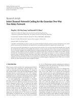
are evaluated over 100 000 bursts. Under these assumptions,
Figure 4(a) shows the probability of nondetection of the op-
timal delay l
o
T
e
by the CONV-LS (C) and OPT-LS (O) re-
ceivers as a function of the input SNR, μ
s
2
π
s
/η
2
,foraFAR
equal to 0.001 and for several values of the number of sen-
sors. Note, for N
= 1, the much better performance of the
OPT-LS receiver due to its capability to reject the rectilin-
ear interference by phase discrimination between the sources.
Note, for 2
≤ N ≤ 4, the better performance reached by the
OPT-LS receiver, due to a better discrimination between the
sources, done jointly by the phase and DOA, and despite of
the fact that the CONV-LS receiver rejects the interference by
a DOA discrimination. Thus, for rectilinear sources, software
may replace sensors for given performances.
Note that when the interference considered previously
corresponds to a useful path different from i
0
, the detec-
tion performances of the useful path i
0
are still given by
12 EURASIP Journal on Advances in Signal Processing
Figure 4(a) as long as the nonuseful path remains decorre-
lated from the useful path i
0
. As the relative delay between the
two paths decreases toward zero, the correlation between the
two paths increases and the spatial filters
w(l
o
T
e
)and
w(l
o
T
e
)
tend to keep the interferent path rather than to reject it. As
a consequence, the power of the interference path tends to
be added to that of the useful path for the detection process,
hence a better detection of the useful path, as it is confirmed
by simulations, nondescribed in the paper.
5. EXTENSION TO MSK AND GMSK SIGNALS
5.1. Extension
We briefly present in this section the extension of the pre-
vious results to MSK and GMSK modulations while a more
detailed analysis of this problem will be presented elsewhere.
The MSK and GMSK modulations [16] belong to the family
of continuous phase modulation (CPM). It has been shown
in [36] that GMSK modulation can be approximated by a lin-
ear modulation, while MSK is a linear modulation. In such
conditions, the complex envelope of a useful MSK or GMSK
signal takes the form
s(t)
≈
n
j
n
b
n
f
t − nT −t
s
. (46)
In (46), the approximated equality becomes a strict equality
foraMSKsignal,b
n
=±1 are the transmitted symbols if
the latter are differentially encoded in the exact form of the
modulation [19], T is the symbol duration, t
s
(0 ≤ t
s
≤ T)is
the time origin of the useful signal, and f (t) is a real-valued
pulse-shaped filter. This filter corresponds to
f (t)
=
⎧
⎪
⎨
⎪
⎩
cos
πt
2T
−
T ≤ t ≤ T
0 otherwise
⎫
⎪
⎬
⎪
⎭
(47)
for a MSK modulation whereas it may correspond either to
the main pulse in Laurent’s decomposition [36] or to the one
computed in [19], which generates the best linear approxi-
mation of the GMSK in a least square sense. In both cases the
temporal support of f (t)foraGMSKmodulationisabout
4T [19].Thederotationoperationpresentedin[18, 19]con-
sists to multiply the signal s(t)byj
−t/T
, giving rise to the
derotated signal, s
d
(t), defined by
s
d
(t) j
−t/T
s(t) ≈
n
b
n
f
d
t −nT −t
s
, (48)
where f
d
(t) j
−(t+t
s
)/T
f (t) is the equivalent pulse shaped fil-
ter of the derotated MSK or linearized GMSK signal. We de-
duce from (48) that s
d
(t) has the form of a BPSK signal but
with two differences with respect to the latter. The first one
is that f
d
(t) is no longer a 1/2 Nyquist filter and intersymbol
interference (ISI) will appear after a matched filtering opera-
tion to the filter f
d
(t). For this reason, the matched filtering
operation to the pulse-shaped filter may not be required for
the synchronization of MSK or GMSK signals. The second
one is that f
d
(t) is no longer a real function but becomes a
complex function. Thus, derotated MSK and GMSK signals
may be interpreted as a BPSK signal which has been filtered
by a nonideal complex propagation channel. For this reason,
it has been shown in [17] that optimal WL spatial filters be-
come sub-optimal for demodulation or synchronization of
MSK or GMSK sources in the presence of interferences of the
same form and that WL spatio-temporal (ST) filters are re-
quired. The number of taps per ST filter has to increase with
the temporal support of f (t)
⊗h(t), where h(t) is the impulse
response of the propagation channel.
ST WL filters with L taps per filter are defined by
y
WL,ST
l
q
+ n
T
(L−1)/2
u=−(L−1)/2
w
u
lT
e
†
x
d
l
q
+ n
−u
T
w
st
lT
e
†
x
d,st
l
q
+ n
T
(49)
if L is odd and
y
WL,ST
l
q
+ n
T
L/2−1
u=−L/2
w
u
lT
e
†
x
d
l
q
+ n
−u
T
w
st
lT
e
†
x
d,st
l
q
+ n
T
(50)
if L is even. In these expressions,
w
u
(lT
e
)are(2N ×1) spatial
filters, x
d
(t) j
−t/T
x(t), x
d
(kT
e
) [x
d
(kT
e
)
T
, x
d
(kT
e
)
†
]
T
,
x
d,st
(kT
e
)and
w
st
(lT
e
)are(2LN × 1) vectors defined by
x
d,st
(kT
e
) [x
d
((k/q +(L − 1)/2)T)
T
, , x
d
((k/q −
(L − 1)/2)T)
T
]
T
and
w
st
(lT
e
) [
w
−(L−1)/2
(lT
e
)
T
, ,
w
(L−1)/2
(lT
e
)
T
]
T
,respectively,ifL is odd and by x
d,st
(kT
e
)
[
x
d
((k/q + L/2)T)
T
, , x
d
((k/q − L/2)T)
T
]
T
and
w
st
(lT
e
)
[
w
−L/2
(lT
e
)
T
, ,
w
L/2
(lT
e
)
T
]
T
,respectively,ifL is even.
The vector
w
st
(lT
e
) minimizes the LS criterion (4)where
y
vWL
((l/q + n)T) =
w(lT
e
)
†
x
v
((l/q + n)T) is replaced by
y
WL,ST
((l/q + n)T). In these conditions, it is straightforward
to show that for MSK and GMSK signals, an LS approach us-
ing WL ST filters gives rise to (9)butwith
x
d,st
((l/q + n)T)
instead of
x
v
((l/q + n)T).
5.2. Performance
To compute and illustrate the performance of the OPT-LS re-
ceiver for MSK and GMSK signals, we consider the scenario
of Figure 4(a) where BPSK sources have been replaced by ei-
ther MSK (M) or GMSK (G) sources and we limit the analysis
to the one sensor case (N
= 1). For the OPT-LS receiver, we
choose L
= 1orL = 3 taps whereas only 1 tap is chosen for
the CONV-LS receiver. Under these assumptions, Figure 4(b)
shows the probability of nondetection of the optimal delay
l
o
T
e
by the CONV-LS and OPT-LS receivers as a function of
Pascal Chevalier et al. 13
the input SNR, μ
s
2
π
s
/η
2
, for a FAR equal to 0.001. Note the
poor performance of both CONV-LS receiver and OPT-LS
receiver for L
= 1 and the good performance of OPT-LS re-
ceiver for L
= 3 for both modulations, showing off the ca-
pability of the OPT-LS receiver to do SAIC for both MSK
and GMSK signals provided ST WL filters are used. Note fi-
nally the better performance of the OPT-LS receiver for MSK
signals due to a smaller time support of the pulse-shaped fil-
ter. More insights about optimal values of L, partially given
in [17] for channels with no delay spread, will be discussed
elsewhere whatever the delay spread of the channel.
6. CONCLUSION
It has been shown in this paper that taking into account the
noncircularity property of rectilinear interferences may dra-
matically improve the performance of both mono- and mul-
tichannels receivers for the synchronization of a BPSK signal
in a radio communication network using this modulation.
This result also holds for other rectilinear modulations such
as AM or ASK modulations. For such signals and noncircular
interferences, the optimal receiver, called OPT-LS receiver,
has been shown to implement an optimal, in an LS sense,
WL spatial filtering of the data followed by a correlation op-
eration with a training sequence. Conditions, not required
in practice, under which this optimal receiver becomes opti-
mal for detection, in terms of GLRT approach, have also been
given. A simplified performance analysis of both the conven-
tional and the optimal receiver has been presented, allowing
to prove in particular the ability of OPT-LS receiver to do sin-
gle antenna interference cancellation and to show a decrease
of the number of sensors for given performances. Besides,
new analytical results about the convergence of the SINR at
the output of both the SMF and the WL SMF, implemented
from a training sequence, has been deduced from simula-
tions. Extensions of the main results of the paper to both
MSK and GMSK modulations have been briefly presented at
the end of the paper. High performance of the OPT-LS re-
ceiver for these modulations have been obtained jointly with
its capability to implement SAIC provided ST WL filters are
used instead of spatial ones.
APPENDIX
It is shown in this appendix that expression (9)forl
= l
o
is
asufficient statistic for the optimal detection, in the GLRT
sense, of the known signal s
v
(nT)(0≤ n ≤ K −1) from the
observation vectors x
v
((l
o
/q+n)T)(0≤ n ≤ K−1), assuming
that assumptions (A1) to (A7) are verified. To this aim, let
us first compute the ML estimates of μ
s
h
s
and of R
b
(l
o
T
e
)
under H1 and H0, respectively. To do so, let us consider the
likelihood of the parameters s
v
(nT)(0≤ n ≤ K − 1), μ
s
h
s
,
R
b
(l
o
T
e
) under H1, observing x
v
((l
o
/q+n)T)(0≤ n ≤ K−1).
Under the previous assumptions, this likelihood, L
1
(l
o
T
e
, K),
can be written as
L
1
l
o
T
e
, K
p
G
(A.1)
(where G
={x
v
((l
o
/q+n)T) = μ
s
s
v
(nT)
h
s
+
b
Tv
((l
o
/q+n)T)/
s
v
(nT), μ
s
h
s
, R
b
(l
o
T
e
), 0 ≤ n ≤ K −1}). Under the previous
assumptions (A1) to (A7), expression (A.1)canbewrittenas
L
1
l
o
T
e
, K
=
K−1
n=0
p
J
n
(A.2)
(where J
n
={
b
Tv
((l
o
/q+n)T) = x
v
((l
o
/q+n)T)−μ
s
s
v
(nT)
h
s
/
s
v
(nT), μ
s
h
s
, R
b
(l
o
T
e
)}), and p[
b
Tv
((l
o
/q + n)T)] is defined
by (15). Using (15) into (A.2) and taking the logarithm of
L
1
(l
o
T
e
, K), we obtain
Log
L
1
l
o
T
e
, K
=−
NKLog(π) −
K
2
Log
det
R
b
l
o
T
e
−
1
2
K−1
n=0
x
v
l
o
q
+ n
T
−
μ
s
s
v
(nT)
h
s
†
×R
b
l
o
T
e
−1
x
v
l
o
q
+ n
T
−
μ
s
s
v
(nT)
h
s
.
(A.3)
Using the fact that
|s
v
(nT)|
2
= r(0)
2
π
s
, it is then straight-
forward to show that the ML estimate,
μ
s
h
s
,ofμ
s
h
s
, that is,
the estimate
μ
s
h
s
which maximizes (A.3)isgivenby
μ
s
h
s
=
1
Kπ
s
K−1
n=0
x
v
l
o
q
+ n
T
s
v
(nT)
∗
. (A.4)
Replacing μ
s
h
s
by μ
s
h
s
into (A.3), it is well known [8, 10] that
the ML estimate,
R
b1
(l
o
T
e
), of R
b
(l
o
T
e
) under H1, that is, the
matrix
R
b1
(l
o
T
e
) which maximizes (A.3)isgivenby
R
b1
l
o
T
e
=
1
K
K−1
n=0
x
v
l
o
q
+ n
T
−
s
v
(nT)μ
s
h
s
×
x
v
l
o
q
+ n
T
−
s
v
(nT)μ
s
h
s
†
.
(A.5)
In a similar way, it is straightforward to show that the ML
estimate,
R
b
0
(l
o
T
e
), of R
b
(l
o
T
e
) under H0 is given by
R
b
0
l
o
T
e
=
1
K
K−1
n=0
x
v
l
o
q
+ n
T
x
v
l
o
q
+ n
T
†
.
(A.6)
On the other hand, using (A.5) into (A.3), we obtain, under
H1,
K−1
n=0
x
v
l
o
q
+ n
T
−
s
v
(nT)μ
s
h
s
†
R
b
1
l
o
T
e
−1
×
x
v
l
o
q
+ n
T
−
s
v
(nT)μ
s
h
s
=
K Tr
R
b1
l
o
T
e
−1
R
b1
l
o
T
e
= NK.
(A.7)
14 EURASIP Journal on Advances in Signal Processing
In a similar way, we obtain, under H0,
K−1
n=0
x
v
l
o
q
+ n
T
†
R
b
0
l
o
T
e
−1
x
v
l
o
q
+ n
T
=
K Tr
R
b0
l
o
T
e
−1
R
b0
l
o
T
e
=
NK.
(A.8)
Then, using (15) into (14), replacing R
b
(l
o
T
e
)by
R
b0
(l
o
T
e
)
under H0, μ
s
h
s
by μ
s
h
s
and R
b
(l
o
T
e
)by
R
b
1
(l
o
T
e
)underH1
and using (A.7)and(A.8), it is straightforward to show that
the likelihood receiver, LR(l
o
T
e
, K), defined by (12), takes the
form
LR
l
o
T
e
, K
=
det
R
b0
l
o
T
e
det
R
b
1
l
o
T
e
K
,(A.9)
where det(A) means determinant of matrix A.Moreover,we
deduce from (A.4), (A.5), and (A.6) that
R
b1
l
o
T
e
=
R
b0
l
o
T
e
−
π
s
μ
s
h
s
μ
s
h
s
†
=
R
b
0
l
o
T
e
1/2
I − π
s
R
b
0
l
o
T
e
−1/2
μ
s
h
s
×
μ
s
h
s
†
R
b0
l
o
T
e
−†/2
R
b0
l
o
T
e
†/2
,
(A.10)
where
R
b0
(l
o
T
e
)
1/2
is a square root of
R
b0
(l
o
T
e
)such
that
R
b0
(l
o
T
e
) =
R
b0
(l
o
T
e
)
1/2
R
b0
(l
o
T
e
)
†/2
,
R
b0
(l
o
T
e
)
†/2
(
R
b
0
(l
o
T
e
)
1/2
)
†
,
R
b
0
(l
o
T
e
)
−†/2
(
R
b
0
(l
o
T
e
)
−1/2
)
†
. Taking the
determinant of the two sides of (A.10) and using the fact that
det[I
−uu
†
] = 1 −u
†
u,weobtain
det
R
b
1
l
o
T
e
=
det
R
b0
l
o
T
e
1 − π
s
μ
s
h
s
†
R
b0
l
o
T
e
−1
μ
s
h
s
.
(A.11)
Using (A.11) into (A.9)wefinallyobtain
LR
x
v
l
o
T
e
, K
=
⎛
⎜
⎝
1
1 − π
s
μ
s
h
s
†
R
b
0
l
o
T
e
−1
μ
s
h
s
⎞
⎟
⎠
K
(A.12)
which shows that a sufficient statistic for the optimal detec-
tion of the known signal s
v
(nT)(0≤ n ≤ K −1) from the
observations x
v
((l
o
/q+n)T)(0≤ n ≤ K −1), assuming (A1)
to (A7), is given by
C
OPT-LS
l
o
T
e
, K
= π
s
μ
s
h
s
†
R
b0
l
o
T
e
−1
μ
s
h
s
=
1
π
s
r
xs
l
o
T
e
†
R
x
l
o
T
e
−1
r
xs
l
o
T
e
.
(A.13)
REFERENCES
[1] S. E. Bensley and B. Aazhang, “Subspace-based channel esti-
mation for code division multiple access communication sys-
tems,” IEEE Transactions on Communications,vol.44,no.8,
pp. 1009–1020, 1996.
[2] S. E. Bensley and B. Aazhang, “Maximum-likelihood syn-
chronization of a single user for code-division multiple-access
communication systems,” IEEE Transactions on Communica-
tions, vol. 46, no. 3, pp. 392–399, 1998.
[3] U. Madhow, “Blind adaptive interference suppression for the
near-far resistant acquisition and demodulation of direct-
sequence CDMA signals,” IEEE Transactions on Signal Process-
ing, vol. 45, no. 1, pp. 124–136, 1997.
[4] U. Madhow, “Blind adaptive interference suppression for
direct-sequence CDMA,” Proceedings of the IEEE, vol. 86,
no. 10, pp. 2049–2069, 1998.
[5] A. Mantravadi and V. V. Veeravalli, “Multiple-access interf-
erence-resistant acquisition for band-limited CDMA systems
with random sequences,” IEEE Journal on Selected Areas in
Communications, vol. 18, no. 7, pp. 1203–1213, 2000.
[6]E.G.Str
¨
om, S. Parkvall, S. L. Miller, and B. E. Otter-
sten, “Propagation delay estimation in asynchronous direct-
sequence code-division multiple access systems,” IEEE Trans-
actions on Communications, vol. 44, no. 1, pp. 84–93, 1996.
[7] D. Zheng, J. Li, S. L. Miller, and E. G. Str
¨
om, “An efficient code-
timing estimator for DS-CDMA signals,” IEEE Transactions on
Signal Processing, vol. 45, no. 1, pp. 82–89, 1997.
[8] L. E. Brennan and I. S. Reed, “An adaptive array signal pro-
cessing algorithm for communications,” IEEE Transactions on
Aerospace and Electronic Systems, vol. 18, no. 1, pp. 124–130,
1982.
[9] R. T. Compton Jr., “An adaptive array in a spread-spectrum
communication system,” Proceedings of the IEEE, vol. 66, no. 3,
pp. 289–298, 1978.
[10] D. M. Dlugos and R. A. Scholtz, “Acquisition of spread spec-
trum signals by an adaptive array,” IEEE Transactions on Acous-
tics, Speech, and Signal Processing, vol. 37, no. 8, pp. 1253–
1270, 1989.
[11] B. Wang and H. M. Kwon, “PN code acquisition using smart
antenna for spread-spectrum wireless communications—part
I,” IEEE Transactions on Vehicular Technology, vol. 52, no. 1,
pp. 142–149, 2003.
[12] J. H. Winters, “Spread spectrum in a four-phase communica-
tion system employing adaptive antennas,” IEEE Transactions
on Communications, vol. 30, no. 5, part 2, pp. 929–936, 1982.
[13] B. Picinbono, “On circularity,” IEEE Transactions on Signal
Processing, vol. 42, no. 12, pp. 3473–3482, 1994.
[14] F. D. Neeser and J. L. Massey, “Proper complex random pro-
cesses with applications to information theory,” IEEE Trans-
actions on Information Theory, vol. 39, no. 4, pp. 1293–1302,
1993.
[15] S. Sfar and K. B. Letaief, “Improved group multiuser detection
with multiple receive antennas in the presence of improper
multi-access interference,” IEEE Transactions on Communica-
tions, vol. 53, no. 4, pp. 560–563, 2005.
[16] J. G. Proakis, Digital Communications, McGraw-Hill, New
York, NY, USA, 3rd edition, 1995.
[17] P. Chevalier and F. Pipon, “New insights into optimal
widely linear array receivers for the demodulation of
BPSK, MSK, and GMSK signals corrupted by noncircular
Pascal Chevalier et al. 15
interferences-application to SAIC,” IEEE Transactions on Sig-
nal Processing, vol. 54, no. 3, pp. 870–883, 2006.
[18] Z. Ding and G. Li, “Single-channel blind equalization for GSM
cellular systems,” IEEE Journal on Selected Areas in Communi-
cations, vol. 16, no. 8, pp. 1493–1505, 1998.
[19] H. Trigui and D. T. M. Slock, “Performance bounds for
cochannel interference cancellation within the current GSM
standard,” Signal Processing, vol. 80, no. 7, pp. 1335–1346,
2000.
[20] P. Chevalier, F. Pipon, and F. Delaveau, “Proc
´
ed
´
e et dis-
positif de synchronisation de liaisons rectilignes ou quasi-
rectilignes en pr
´
esence d’interf
´
erences de m
ˆ
eme nature,”
Patent FR.05.01784, February 2005.
[21] B. Picinbono and P. Chevalier, “Widely linear estimation with
complex data,” IEEE Transactions on Signal Processing, vol. 43,
no. 8, pp. 2030–2033, 1995.
[22] W. Brown and R. Crane, “Conjugate linear filtering,” IEEE
Transactions on Information Theory, vol. 15, no. 4, pp. 462–
465, 1969.
[23] W. A. Gardner, “Cyclic Wiener filtering: theory and method,”
IEEE Transactions on Communications, vol. 41, no. 1, pp. 151–
163, 1993.
[24] W. A. Gardner, Cyclostationarity in Communications and Sig-
nal Processing, IEEE Press, New York, NY, USA, 1994.
[25] P. Chevalier, “Filtrage d’antenne optimal pour signaux non
stationnaires-concepts, performances,” in Proceedings of the
15th GRETSI Symposium on Signal and Image Processing,pp.
233–236, Juan-Les-Pins, France, September 1995.
[26] P. Chevalier, “Optimal array processing for non stationary sig-
nals,” in Proceedings of IEEE Internat ional Conference on Acous-
tics, Speech, and Signal Processing (ICASSP ’96), vol. 5, pp.
2868–2871, Atlanta, Ga, USA, May 1996.
[27] P. Ciblat, P. Loubaton, E. Serpedin, and G. B. Giannakis, “Per-
formance analysis of blind carrier frequency offset estima-
tors for noncircular transmissions through frequency-selective
channels,” IEEE Transactions on Signal Processing, vol. 50,
no. 1, pp. 130–140, 2002.
[28] P. Ciblat, E. Serpedin, and Y. Wang, “On a blind fractionally
sampling-based carrier frequency offset estimator for noncir-
cular transmissions,” IEEE Signal Processing Letters, vol. 10,
no. 4, pp. 89–92, 2003.
[29] A. Napolitano and M. Tanda, “Doppler-channel blind identi-
fication for noncircular transmissions in multiple-access sys-
tems,” IEEE Transactions on Communications, vol. 52, no. 12,
pp. 2073–2078, 2004.
[30] P. Chevalier and F. Pipon, “Optimal array receiver for syn-
chronization of a BPSK signal corrupted by non circular inter-
ferences,” in Proceedings of IEEE International Conference on
Acoustics, Speech, and Signal Processing (ICASSP ’06) , vol. 4,
pp. 1061–1064, Toulouse, France, May 2006.
[31] H. L. van Trees, Detection, Estimation and Modulation
Theory—Part I, John Wiley & Sons, New York, NY, USA, 1968.
[32] F. Delaveau, F. Pipon, and O. Lambron, “Smart antennas for
interference resolution in cellular networks,” in Proceedings of
the 14th International Wroclaw Symposium and Exhibition on
Electromagnetic Compatibility, pp. 264–267, Wroclaw, Poland,
June 1998.
[33] B. Picinbono, “Second-order complex random vectors and
normal distributions,” IEEE Transactions on Signal Processing,
vol. 44, no. 10, pp. 2637–2640, 1996.
[34] A. van den Bos, “The multivariate complex normal
distribution—a generalization,” IEEE Transactions on In-
formation Theory, vol. 41, no. 2, pp. 537–539, 1995.
[35] R. A. Monzingo and T. W. Miller, Introduction to Adaptive Ar-
rays, John Wiley & Sons, New York, NY, USA, 1980.
[36] P. A. Laurent, “Exact and approximate construction of digital
phase modulations by superposition of amplitude modulated
pulses (AMP),” IEEE Transactions on Communications, vol. 34,
no. 2, pp. 150–160, 1986.
Pascal Chevalier received the M.S. degree
from Ecole Nationale Sup
´
erieure des Tech-
niques Avanc
´
ees (ENSTA) and the Ph.D. de-
gree from South-Paris University, France,
in 1985 and 1991, respectively. Since 1991
he has been with Thomson-CSF/RGS (now
Thal
´
es-Communications) where has shared
industrial activities (studies, experimenta-
tions, expertises, management), teaching
activities both in French engineer schools
(ESE, ENST, ENSTA) and French universities (Cergy-Pontoise) and
research activities. Since 2000, he has also been acting as a Technical
Manager and Architect of the array processing sub-system as part
of a national program of military satellite telecommunications. He
is currently a Thal
´
es Expert since 2003. His present research inter-
ests are in array processing techniques for applications such as ra-
diocommunications networks, satellite telecommunications, spec-
trum monitoring, and passive listening in HVUHF band. He has
been a Member of the THOMSON-CSF Technical and Scientifical
Council between 1995 and 1998. He coreceived the 2003 “Science
and Defense” Award from the French Ministry of Defence for its
work as a whole about array processing for military radiocommu-
nications. He is author or coauthor of about 20 patents and 100 pa-
pers. He is presently an EURASIP member and an emeritus Mem-
ber of the Societ
´
e des Electriciens et des Electroniciens (SEE).
Franc¸ois Pipon was born in 1964 in Melle
(Deux-S
`
evres), France. He received the M.S.
degree both from Ecole Polytechnique and
Ecole Nationale Sup
´
erieure des Techniques
Avanc
´
ees (ENSTA) in 1987 and 1989, re-
spectively. In 1989, he joined Thomson
CSF/RGS (now Thal
`
es-Communications)
as an Engineer in the field of array pro-
cessing, working on both direction finding
and adaptive array filtering aspects. Since
1993, he has shared industrial activities (studies, experimenta-
tions, expertises, management, etc.), and research activities. Since
1998, he has worked on a multichannel interference analyser prod-
uct (SMART AIR) for the GSM network. He has developed most
of the antenna processing techniques implemented in the equip-
ment. His present research interests are in multichannel equal-
izer techniques, for applications such as TDMA (especially the
GSM network) and CDMA radiocommunications networks, satel-
lite telecommunications, HF telecommunications, spectrum mon-
itoring, and HF/VUHF passive listening. He coreceived the 2003
“Science and Defense” Award from the French Ministry of Defence
for its work as a whole about array processing for military radio-
communications. He is author or coauthor of 14 patents and more
than 20 papers (journal and conferences).
16 EURASIP Journal on Advances in Signal Processing
Franc¸ois Delaveau was born in 1964 in
Argenteuil, France, he received the M.S.
degrees from Ecole Nationale Sup
´
erieure
de Techniques Avanc
´
ees (ENSTA), Paris,
France, in 1987, and from Mathematics
University (Ma
ˆ
ıtrise and Agr
´
egation - 1988
and 1990). Since 1987, he shares industrial
activities (studies, experimentation, man-
agement, etc.) and research activities. After
working in RADAR, SONAR, infra-red, and
acoustic systems for various advanced militarian applications, he
joined Thomson CSF/COMSYS in 1997 to develop a new line of
RF instruments for spectrum monitoring applications. He was in-
volved either in signal processing applications focused on terrestrial
and satellite transmissions, in adaptive array techniques dedicated
to interference measurement within OFDM, TDMA, and CDMA
networks, in advanced developments related to COMINT appli-
cations, regarding especially radiocellulars and civilian standards.
He is currently a Thales expert for radiocellulars and he manages
a laboratory of THALES communication that is dedicated to sig-
nal analysis and antenna processing. He is author or coauthor of
many papers, ITU recommendations, and Thal
´
es patents for signal
measurement.