Báo cáo hóa học: " Self-assembled GaInNAs/GaAsN quantum dot lasers: solid source molecular beam epitaxy growth and high-temperature operation" pptx
Bạn đang xem bản rút gọn của tài liệu. Xem và tải ngay bản đầy đủ của tài liệu tại đây (495.77 KB, 12 trang )
Abstract Self-assembled GaInNAs quantum dots
(QDs) were grown on GaAs (001) substrate using solid-
source molecular-beam epitaxy (SSMBE) equipped
with a radio-frequency nitrogen plasma source. The
GaInNAs QD growth characteristics were extensively
investigated using atomic-force microscopy (AFM),
photoluminescence (PL), and transmission electron
microscopy (TEM) measurements. Self-assembled
GaInNAs/GaAsN single layer QD lasers grown using
SSMBE have been fabricated and characterized. The
laser worked under continuous wave (CW) operation at
room temperature (RT) with emission wavelength of
1175.86 nm. Temperature-dependent measurements
have been carried out on the GaInNAs QD lasers.
The lowest obtained threshold current density in this
work is ~1.05 kA/cm
2
from a GaInNAs QD laser
(50 · 1,700 lm
2
)at10°C. High-temperature operation
up to 65 °C was demonstrated from an unbonded
GaInNAs QD laser (50 · 1,060 lm
2
), with high char-
acteristic temperature of 79.4 K in the temperature
range of 10–60 °C.
Keywords GaInNAs Æ Quantum dot Æ Laser diodes Æ
Molecular beam epitaxy (MBE)
Introduction
Long-wavelength 1.3 lm or 1.55 lm semiconductor
lasers are key devices for optical fiber communications
and have attracted much attention in recent years due
to their zero dispersion and minimal absorption in sil-
ica fibers. Nowadays, nearly all commercialized semi-
conductor lasers operating at wavelength of 1.3 lm and
1.55 lm are made from the InGaAsP/InP material
system. The InGaAsP/InP material system, however,
exhibits relatively poor electron confinement in the
well layers due to rather small band offsets in the
conduction band between the well and cladding layers
(DE
c
= 0.4 DE
g
). As a result, such lasers demonstrate
relatively inferior high temperature characteristics,
namely, device performance is strongly temperature
dependent [1]. Although the lasing properties of
1.3-lm and 1.55-lm InGaAsP/InP lasers have been
improved using strained multi-quantum well (QW)
layers, the performance at high temperature is still
unsatisfactory compared with that of short-wavelength
lasers on GaAs substrate [2].
Therefore, there has been a large research effort to
find GaAs-based solutions to realize 1.3 lm and
1.55 lm lasers. GaInNAs is a promising candidate for
long wavelength emission first proposed by Kondow
et al. [3, 4]. For many years it was believed that there
was no suitable alloy lattice-matched to GaAs at
emission wavelength > 1.1 lm. Contrary to the gen-
eral rules of III–V alloy semiconductors, where a
smaller lattice constant increases the bandgap, the
large electronegativity of N and its small atomic size
results in strong negative bowing parameter. The
addition of N to GaAs or InGaAs significantly
decreases the bandgap and lattice constants. Adding In
S. F. Yoon (&) Æ C. Y. Liu Æ Z. Z. Sun Æ K. C. Yew
Compound Semiconductor and Quantum Information
Group School of Electrical and Electronic Engineering,
Nanyang Technological University, Nanyang Avenue,
Singapore 639798, Rep. of Singapore
e-mail:
Nanoscale Res Lett (2006) 1:20–31
DOI 10.1007/s11671-006-9009-5
123
NANO REVIEW
Self-assembled GaInNAs/GaAsN quantum dot lasers:
solid source molecular beam epitaxy growth and
high-temperature operation
S. F. Yoon Æ C. Y. Liu Æ Z. Z. Sun Æ K. C. Yew
Published online: 26 July 2006
Ó to the authors 2006
reduces the bandgap, while increasing the lattice con-
stant. By combining N and In, a rapid decrease in
bandgap in GaInNAs is obtained; thus allowing the
possibility to reach long wavelength emission with
simultaneous control over the bandgap and lattice
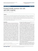
matching to GaAs [3–6]. Figure 1 shows the relation-
ship between the lattice constant and bandgap energy
in III–V alloy semiconductors, taking into account the
significant bandgap bowing in GaAsN [4]. It can be
seen that the N-containing III–V semiconductors sig-
nificantly expand the application area of III–V alloy
semiconductor and increase the freedom for designing
semiconductor devices [3, 4]. Since GaInNAs is grown
on GaAs substrate, the technically matured GaAs/Al-
GaAs distributed Bragg reflectors (DBRs) can be used
in the GaInNAs vertical cavity surface emitting lasers
(VCSELs). The GaAs/AlGaAs bi-layer has larger
index difference (~0.7) than the InGaAsP/InP combi-
nation. This allows for easier fabrication of DBRs for
GaInNAs/GaAs-based devices. Furthermore, GaIn-
NAs/GaAs QW exhibits a large conduction band off-
set, thus allowing for better thermal performance in
GaAs-based GaInNAs lasers. These remarkable fun-
damental properties of Ga(In)NAs alloys provide an
opportunity to tailor the material properties for desired
applications in optoelectronic devices based on III–V
materials [3–6].
Due to above advantages, in the past few years,
there has been considerable interest in GaInNAs
materials grown on GaAs substrate for realizing low-
cost, high-performance and high-temperature laser
diodes in the 1.3 lm and 1.55 lm wavelength region.
So far, GaInNAs QW laser performance has been
improved significantly [3–19]. Both GaInNAs Fabry-
Perot edge-emitting lasers [3–18] and VCSELs [19]
have been realized. For edge-emitting 1.3-lm GaIn-
NAs lasers, Tansu et al. [14] reported the lowest
transparency current density (J
tr
) of 75–80 A/cm
2
from
structures grown by metal organic chemical vapor
deposition (MOCVD); Wang et al. [11] recently
reported J
tr
of 84 A/cm
2
from 1.3-lm GaInNAs lasers,
grown using molecular beam epitaxy (MBE). More
recently, 10-Gb/s transmission using floor free GaIn-
NAs triple-QW (TQW) ridge waveguide (RWG) lasers
have been successfully demonstrated [13]. Undoubt-
edly, GaInNAs 1.3-lm QW lasers present excellent
potential for telecommunication application.
Meanwhile, studies on GaInNAs quantum dot (QD)
structures have also attracted much interest, since QD
lasers, with three-dimensional carrier confinement, are
anticipated to have many advantages over their QW
counterparts, such as decreased J
tr
, increased differen-
tial gain, high characteristic temperature (T
0
), and lar-
gely extended emission wavelength [20, 21]. Moreover,
in the case of GaInNAs QD lasers, reduction in bandgap
energy with N incorporation decreases the dot sizes for
long wavelength emission. Smaller dots have larger sub-
band energy difference, resulting in suppression of
carrier leakage to high energy states. Furthermore,
smaller dot sizes are also advantageous for obtaining
high QD density [22]. Compared to GaInNAs QW, the
advantage of using GaInNAs QDs is the expectation to
achieve the same long wavelength emission with rela-
tively lower N content; an effect assisted by the wave-
length extension ability of the strained 3D islands. The
high N content needed for long wavelength emission in
GaInNAs QW lasers deteriorates the optical charac-
teristics of the material and limits the device perfor-
mance. It is hoped that the lower N content in GaInNAs
QDs will help alleviate this problem without compro-
mising device performance.
Recently, GaInNAs QDs have been successfully
grown using MBE [23–30], chemical beam epitaxy
(CBE)[22, 31–34] and MOCVD [35–38]. Photolumi-
nescence (PL) emission in the 1.3 lm and 1.5 lm region
from MBE-grown GaInNAs QDs has been observed
[23]. However, compared with a large amount of
research on GaInNAs QW lasers [3–19], relatively
fewer results on GaInNAs QD lasers have been re-
ported [30, 31, 38]. Makino et al. first reported pulsed
lasing from a CBE-grown Ga
0.5
In
0.5
N
0.01
As
0.99
QD laser
at 77 K at emission wavelength of 1.02 lm and thresh-
old current density (J
th
) of 1.9 kA/cm
2
[31]. Recently,
Gao et al. reported pulsed lasing from MOCVD-grown
GaInNAs QD RWG lasers at room temperature (RT)
with emission wavelength at 1078 nm [38]. However,
their GaInNAs QD RWG laser (4 · 800 lm
2
) showed
relatively high J
th
of ~13 kA/cm
2
. We have recently
achieved RT continuous wave (CW) operation of
Ga
0.7
In
0.3
N
0.01
As
0.99
QD edge-emitting lasers, grown by
Fig. 1 The relationship between the lattice constant and band-
gap energy in III–V alloy semiconductors [4]
Nanoscale Res Lett (2006) 1:20–31 21
123
solid source MBE (SSMBE). To the best of our
knowledge, this is the first ever report on RT, CW lasing
from GaInNAs QD lasers [30].
This paper deals with the various aspects of material
characteristics of self-assembled GaInNAs QD struc-
ture grown by SSMBE using a radio-frequency nitrogen
plasma source. Structural and optical properties of
GaInNAs QD structures have been extensively inves-
tigated using atomic force microscopy (AFM), PL, and
transmission electron microscopy (TEM) measure-
ments. The effect of growth temperature and interme-
diate layer on GaInNAs QD properties is discussed.
GaInNAs/GaAsN single layer QD lasers have been
fabricated and characterized. The laser worked under
RT, CW operation with emission wavelength centered
at 1175.86 nm. Temperature-dependent measurements
have also been carried out on the GaInNAs QD lasers of
various cavity lengths. The lowest obtained J
th
in this
work is ~1.05 kA/cm
2
from a GaInNAs QD laser
(50 · 1,700 lm
2
)at10°C. High-temperature operation
up to 65 °C was successfully demonstrated from an
unbonded GaInNAs QD laser (50 · 1,060 lm
2
), with
high T
0
of 79.4 K in the temperature range of 10–60 °C.
Experimental details
The GaInNAs QD structures were grown on GaAs
(100) by SSMBE with plasma assisted N source. The N
composition in the GaInNAs QDs and GaAsN barriers
was kept at 1% by controlling the flow rate of high
purity nitrogen and rf power, while the In composition
was varied from 30% to 100% for different samples.
The GaInNAs QD layers were grown at 480–500 °C
under As
4
/Ga beam equivalent pressure ratio of 18.
During GaInNAs deposition, the reflection high-en-
ergy electron diffraction (RHEED) pattern trans-
formed from streaky to spotty characteristic, indicating
initiation of the self-organized islanding process of
two-to-three dimensional transition. AFM measure-
ments were performed in uncapped GaInNAs QD
samples grown under identical conditions. PL mea-
surements were performed in a closed-cycle helium
cryostat. The PL spectrum was excited by an Ar
+
514.5 nm laser and detected by a cooled Ge detector.
The formation of GaInNAs QDs was extensively
confirmed to follow the conventional Stranski-Krasta-
now (SK) growth mode. Furthermore, AFM observa-
tion of change in surface morphology of samples with
different GaInNAs monolayer (ML) thickness con-
firms the nucleation of QDs after a certain number of
MLs. The existence of GaInNAs dots in capped sam-
ples was also observed by TEM. With AFM, PL, and
TEM measurements, structural and optical properties
of GaInNAs QD structures have been extensively
investigated. Furthermore, the effects of growth tem-
perature and intermediate layer on GaInNAs QD
properties were also studied.
For the GaInNAs QD laser studied here, the QD
active region consisted of a 28-ML Ga
0.7
In
0.3
N
0.01
As
0.99
QD layer with two 5-nm-thick GaAsN
0.01
barrier lay-
ers, which was inserted between the undoped 0.1-
lm-thick GaAs waveguide layers. The whole wave-
guide core was then inserted between the 1.5-lm-thick
n- and p-type Al
0.35
Ga
0.65
As cladding layers. Finally, a
200-nm-thick p
+
-GaAs cap layer was grown for elec-
trical contact purpose. Carbon and silicon were used as
the p- and n-type dopants, respectively.
Self-assembled GaInNAs QD broad area lasers
were fabricated with contact stripe width (w)of50lm
using conventional SiO
2
confinement method. P-type
ohmic contact layers (Ti/Au, 50/250 nm) were depos-
ited by electron beam evaporation. The wafer sub-
strates were then lapped down to about 100 lm thick
to facilitate laser chip cleaving. AuGe alloy (Au 88%
by weight, 150 nm) and Ni/Au multiple layers (30/
250 nm) were deposited by electron beam evaporation
on the thinned and polished n-GaAs substrate as n-
type ohmic contact. The wafers were then annealed at
410 °C for 3 min in N
2
ambient to alloy both the p-type
and n-type ohmic contacts. After fabrication, individ-
ual GaInNAs QD lasers were then cleaved at different
cavity length (L) for measurement of laser output
power (P) versus injection current (I)(P – I) charac-
teristics without facet coating. The devices were tested
under both CW and pulsed operation. For the CW
testing, the GaInNAs QD lasers were p-side-down
bonded onto copper heat sinks. Temperature-depen-
dent P – I characteristics have also been tested on the
as-cleaved, unbonded GaInNAs QD lasers. In order to
reduce the device heating, the temperature-dependent
measurements were carried out under pulsed operation
at pulse frequency of 20 kHz, pulse width of 500 ns,
and duty cycle of 1%. The temperature of the laser was
controlled by a thermoelectrically cooled circuit
(TEC), which can be varied from 10 °Cto80°C. The
output power of the laser (from one facet) was mea-
sured by a calibrated InGaAs photodetector mounted
in an integration sphere.
Results and discussion
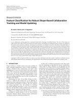
Figure 2(a–c) shows the AFM images of the surface
morphology of Ga
0.6
In
0.4
N
0.01
As
0.99
QD samples of
different thickness from 3 ml to 6 ml grown by SSMBE
22 Nanoscale Res Lett (2006) 1:20–31
123
at 0.5 ml/s and As
4
/Ga beam equivalent pressure
(BEP) ratio of 18. As shown in Fig. 2a, the surface
appears to be atomically flat at 3 ml thickness, with
root mean square (RMS) roughness of ~0.4 nm. When
the GaInNAs thickness is increased to 4 ml, low den-
sity (~1.8 · 10
10
cm
–2
) dots began to form as shown in
Fig. 2b, indicating initiation of the self-organized QD
formation process. At GaInNAs thickness of 6 ml,
dense dots with sheet density of ~6 · 10
10
cm
–2
can be
seen from the AFM image in Fig. 2c. The dots have
average height of ~5 nm and lateral diameter of
~33 nm with relatively homogenous distribution.
Further increase in thickness to 7 ml and beyond
results in coalescence of the dots leading to significant
surface roughening (RMS surface roughness > 2 nm).
Figure 2d and e show the cross-sectional TEM images
of 4.5 ml-thick Ga
0.6
In
0.4
N
0.01
As
0.99
QDs and 5 ml-
thick Ga
0.5
In
0.5
N
0.01
As
0.99
QDs multilayer samples,
respectively. The images show coherent dot profile
with aspect ratio of ~0.1. This is in good agreement
with the AFM measurements, in terms of dot size.
The critical thickness is an important parameter
governing the self-organized growth kinetics. Using in
situ RHEED observation, the transition time to change
from 2D to 3D growth mode can be used to estimate
the value of critical thickness. Critical thickness values
of 3 ml and 2.5 ml have been reported for gas-source
molecular beam epitaxy (GSMBE)-grown Ga
0.3
In
0.7-
N
0.04
As
0.96
and InN
0.02
As
0.98
QDs, respectively [23]. For
metalorganic vapor phase epitaxy (MOVPE)-grown
11.32
[nm]
0.00
500.00 nm 1.00 x 1.00 um
3.00
[nm]
0.00
500.00 nm
1.00 x 1.00 um
2.03
[nm]
0.00
1.00 um
2.00 x 2.00 um
10nm
(001)
(d)
(c)
(b)
(a)
(e)
Fig. 2 AFM images of: (a)
3 ml-thick, (b) 4 ml-thick, and
(c) 6 ml-thick
Ga
0.6
In
0.4
N
0.01
As
0.99
QD
samples. Cross-sectional
TEM images of (d) 4.5 ml-
thick Ga
0.6
In
0.4
N
0.01
As
0.99
QDs and (e) 5 ml-thick
Ga
0.5
In
0.5
N
0.01
As
0.99
QDs
multilayer
Nanoscale Res Lett (2006) 1:20–31 23
123
Ga
0.4
In
0.6
(N)As QDs [35], critical thickness value of
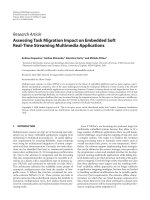
3 ml has been reported. Figure 3 shows the variation in
critical thickness for SSMBE-grown GaInNAs QDs of
different In compositions (30–100%) as function of N
composition (0–1.5%). It can be seen that the GaIn-
NAs critical thickness decreased drastically from
10–15 nm to < 1 nm as the In composition is in-
creased from 30% to 100%. This is because the
GaInNAs-to-GaAs layer strain is mainly determined
by the In composition at low N content. For GaInNAs
samples of the same In composition, the dependence of
critical thickness on N composition show obvious
fluctuations with respect to theoretical expectation. In
general, the critical thickness required for spontaneous
SK island formation is inversely proportional to square
of the misfit of the strained layer [39, 40]. This is rep-
resented by dotted lines in the figure. It can be seen
that the experimental data is quite different from the-
oretical expectations. A possible reason for such
deviation is the non-uniformity in composition or
strain in the GaInNAs layer, which will be discussed
further in the following section. Furthermore, it was
found that the fluctuation of critical thickness is less
significant in GaInNAs at higher In composition. This
could suggest that the non-uniformity in composition
or strain caused by N incorporation plays a relatively
weaker role compared to the strain effects at high In
composition.
Depending on growth conditions [23, 34, 35],
GaInNAs QD density can reach levels as high as 10
10
–
10
11
cm
–2
with average dot height in the range of
2–16 nm and dot lateral diameter in the range of
20–45 nm. Thickness and material composition are
basic parameters, which impact the QD structural
properties. Figure 4 shows the dot density and average
dot height of GaInNAs QDs grown by SSMBE, as
function of thickness at different In composition [41].
As expected, increasing the surface coverage results in
greater dot density and dot height. Moreover, for
GaInNAs of high In composition, high-density dots can
be formed at relatively lower surface coverage. Besides
smaller critical thickness in GaInNAs at high In com-
position, another possible reason for this observation is
the strong local strain caused by N incorporation. This
enhances the formation of strained dots, especially in
GaInNAs of high In composition [42]. The incorpora-
tion of N has a complicated influence on the QD size
and density. Some experiments have suggested that
low N incorporation results in smaller GaInNAs QD
size and much higher dot density compared to InGaAs
QDs grown under identical conditions [23, 31, 35].
However, this behavioral trend may not be true at N
composition > 1%, where there are reports of dot
coalescence resulting in low-density, large sized inco-
herent GaInNAs dots [23, 31, 33]. On the contrary,
some experiments on InNAs QDs [43] and GaInNAs
QDs [44] grown by GSMBE have shown that intro-
duction of N induces a reduction in dot density and
increase in dot sizes. As far as QD size uniformity is
concerned, experiments have shown that the growth
0.0 0.2 0.4 0.6 0.8 1.0 1.2 1.4
0
2
4
6
8
10
12
14
16
18
InAsNx
In
0.7
GaAsNx
In
0.5
GaAsNx
In
0.3
GaAsNx
irCt laciT hnkcin( sse)m
N Com
p
ositon
(
%
)
Fig. 3 The variation in critical thickness for SSMBE-grown
GaInNAs QDs with different In and N compositions, estimated
from RHEED observations
1
10
0 2 4 6 8 10121416
In=100%
In=30%
In=40%
In=50%
In=70%
(a)
Dsneti01(y
01
mc
2-
)
0246810121416
0
2
4
6
8
I
=n
%001
In=30%
In=50%
In=40%
In=70%
(b)
GaInNAs Covera
g
e (ML)
He thgi)mn(
Fig. 4 (a) Dot density, and (b) Average dot height measured by
AFM as function of GaInNAs surface coverage. The In
composition was varied from 30% to 100%. The N composition
was 0.4% for the sample with 70% In and ~1% for all other
samples. The lines serve as guide for the eye
24 Nanoscale Res Lett (2006) 1:20–31
123
kinetics governing GaInNAs and InGaAs QD forma-
tion are significantly different [23, 43].
In terms of the optical properties of GaInNAs QDs,
the principal target is to extend the emission wave-
length. As a rough estimate, 1% of N incorporation
will cause ~200 meV in energy shift assuming bowing
coefficient of 20 eV. The effectiveness of N incorpo-
ration on wavelength extension had been experimen-
tally confirmed. Figure 5 shows the PL spectrum from
a sample with one Ga
0.7
In
0.3
As QD layer and one
Ga
0.7
In
0.3
N
0.006
As QD layer grown by SSMBE under
identical conditions. Separate PL peaks were detected
from the two different QD layers. It can be seen that
the PL peak was shifted by 45 nm (or ~56 meV) fol-
lowing the introduction of ~0.6% N into the
Ga
0.7
In
0.3
N
0.006
As QD layer. This clearly shows the
effect of N incorporation on the emission property of
GaInNAs QDs. Similar results on red shift in energy
from ~1.2 eV to 1.08 eV was reported for SSMBE-
grown Ga
0.7
In
0.3
AsN QDs following increase in N
content from 0% to ~1% [24]. Ballet et al. [43] have
reported RT emission at ~1.28 lm(~0.97 eV) from
InAsN/GaAs QDs with 0.8% N. This represents a
80 meV energy shift compared to emission at 1.18 lm
(~1.05 eV) from InAs/GaAs QDs grown by GSMBE.
Furthermore, it was reported that increasing the N
content to 2.1% has failed to extend the wavelength
further in this experiment. This could be due to non-
uniform N concentration in the InAsN QDs and the
presence of defects at high N levels. Sopanen et al. [23]
have reported PL emission at 1.3 lm and 1.52 lm from
4 ml-Ga
0.3
In
0.7
N
0.02
As
0.96
QDs and 5.5 ml-Ga
0.3
In
0.7
N
0.04
As
0.96
grown by GSMBE. Although the PL spec-
trum was relatively weak and broad, the results paved
the way for long wavelength tuning using such QD
layers.
Apart from N concentration, the QD size, which
depends on the layer thickness, also affects the emis-
sion wavelength due to its effect on the quantum
confinement. Figure 6(a–c) shows the 5 K PL spectra
of SSMBE-grown Ga
0.5
In
0.5
N
0.01
As
0.99
QDs of differ-
ent layer thickness from 4 ml to 7.5 ml. No PL signal
from the wetting layer was detected, and each spec-
trum shows a strong PL peak originating from the QD
layer. Generally, the PL peaks are relatively broad due
to fluctuation in QD sizes, and the full-width at half
maximum (FWHM) ranges from 60 nm to 90 nm. As
the thickness of the dot layer is increased from 4 ml to
7.5 ml, the PL peak red-shifted from 900 nm to
1,100 nm. The shift to longer wavelength is attributed
to increase in dot sizes. However, this method has its
limitations as the thickness continues to increase, since
significant structural degradation will occur as the
strain accumulates following increase in thickness. It
can be seen that the 5 ml-thick Ga
0.5
In
0.5
N
0.01
As
0.99
QD sample exhibits the strongest PL intensity, due to
its higher dot density compared to the 4 ml-thick
sample. At 7.5 ml, the PL intensity dropped rather
significantly, suggesting the formation of strain-
induced defects caused by high surface coverage.
Similar observation is also reported for GaInNAs QDs
grown by GSMBE [45].
In the well-studied InGaAs/GaAs QD system,
modifying the dot structures by combining layers with
different composition has proven to be effective for
controlling the physical properties of self-assembled
1000 1050
1100
1150 1200
5K
PL ytisnetnI).u.a(
Experiment
Fitting
GaAs
Ga
0.7
In
0.3
N
0.006
As Dots
Ga
0.7
In
0.3
As Dots
GaAs sub
GaAs cap
Wavelength (nm)
Fig. 5 PL spectra from SSMBE-grown sample with one
Ga
0.7
In
0.3
As dot layer and one Ga
0.7
In
0.3
N
0.006
As dot layer
900 1000 1100 1200 1300
)
.u.a(
ytisnetnILP
(c) 7.5ML
(b) 5ML
(a) 4ML
Ga
0.5
In
0.5
N
0.01
As
0.99
dots 5K
Wavelen
g
th (nm)
Fig. 6 5 K PL spectra of: (a) 4ml-thick, (b) 5 ml-thick, (c)
7.5 ml-thick Ga
0.5
In
0.5
N
0.01
As
0.99
QDs
Nanoscale Res Lett (2006) 1:20–31 25
123
QDs [46, 47]. Generally, this method usually involves
introducing an intermediate layer before and/or after
the QD layer. Such layers are also known as strain
reducing layer (SRL) or strain compensating layer
(SCL). The intermediate layer has different lattice
constant or energy gap compared to the dot layer and
barrier layer. Its presence will modify the strain field or
quantum confinement conditions of the dot layer. A
properly designed intermediate layer can improve the
dot size uniformity and extend the emission wave-
length. There have been some studies on GaInNAs
QDs, where GaAsN intermediate layers were inserted
between the GaAs barrier and GaInNAs QD layer for
extending the emission wavelength of the GaInNAs
QDs. Nishikawa et al. have reported a study which
compared GSMBE-grown GaInN
0.02
As/GaAs QD
samples with: (a) no intermediate layer, (b) GaAsN
0.02
intermediate layer after the dots, and (c) GaAsN
0.02
intermediate layers before and after the dots [45]. Due
to lower confinement provided by the GaAsN inter-
mediate layer compared to GaAs, the QD emission
wavelength shifts to 1.38 lm at 10 K and 1.48 lmat
RT with GaAsN intermediate layer. However, this is
accompanied by decrease in the PL intensity. We have
investigated the effect of GaAsN intermediate layer on
the surface morphology of SSMBE-grown GaInNAs
QDs. Figure 7 shows the AFM images taken on
uncapped 5 ml-thick Ga
0.5
In
0.5
N
0.01
As
0.99
QD samples
with GaAsN intermediate layer of different thickness
(0, 5, and 10 nm). Figure 7a shows GaInNAs QDs
grown on GaAs have average diameter d ~33 nm,
height h ~5 nm, and surface density q ~ 8.6 · 10
10
/
cm
2
. As seen in Fig. 7b, GaInNAs dots grown on 5 nm-
thick GaAsN have similar dot sizes and density
(d ~ 30 nm, h ~ 4.8 nm, q ~ 1.1 · 10
11
/cm
2
) and ap-
peared to have better uniformity. However, increasing
the GaAsN thickness to 10 nm or more resulted in
significant increase in surface roughness, as shown in
Fig. 7c. In this case, the GaInNAs dots appeared rather
irregular with poor uniformity. The change in QD
uniformity associated with the GaAsN intermediate
layer before the dot layer is possibly due to the intro-
duction of composition/thickness modulation by the
intermediate layer. The GaAsN intermediate layer
may form slight undulations and the resulting surface
strain will assume certain periodic characteristic, where
preferential GaInNAs QD nucleation on some peri-
odic sites may occur. Furthermore, a GaAsN inter-
mediate layer inserted above the QD layer can reduce
the strain between the QD layer and GaAs cap layer.
This can lower the formation of interface dislocations.
However, an overly thick GaAsN intermediate layer
should be avoided to minimize dislocation formation
due to strong surface undulations caused by high total
strain energy.
Based on the above mentioned results on structural
and optical properties of GaInNAs QDs, self-assem-
bled Ga
0.7
In
0.3
N
0.01
As
0.99
/GaAsN
0.01
single layer QD
laser structure has been grown. The growth details
11.71
[nm]
0.00
(a)
200.00 nm
10.60
[nm]
0.00
200.00 nm
(b)
22.06
[nm]
0.00
200.00 nm
(c)
Fig. 7 Comparison of AFM morphology of uncapped Ga
0.5
In
0.5-
N
0.01
As
0.99
QD samples with different GaAsN
0.01
intermediate
layer thickness of (a) 0 nm, (b) 5 nm, and (c) 10 nm. The
scanned area is 0.5 lm · 0.5lm
26 Nanoscale Res Lett (2006) 1:20–31
123
have been included in Section 2. Figure 8a shows the
schematic cross-section, layer structure and band dia-
gram of the fabricated Ga
0.7
In
0.3
N
0.01
As
0.99
/GaAsN
0.01
single layer QD edge emitting laser (not to scale).
Figure 8(b) shows the TEM image of the GaInNAs
QD active region.
Figure 9 shows the typical RT, CW P – I charac-
teristics of a p-side down bonded GaInNAs QD laser
with dimension of 50 · 2,000 lm
2
. The laser has
threshold current (I
th
) of 2.2 A, corresponding to J
th
of
~2.2 kA/cm
2
, which was determined by the measured
I
th
divided by contact area (w · L). Light output
power of 16 mW/facet was achieved from this device.
The inset of Fig. 9 shows the lasing spectrum of the
same laser with peak wavelength centered at
1175.86 nm and mode width D k of 0.037 nm. The laser
emission spectra were measured in CW mode using a
spectrometer with resolution of 0.025 nm, an InGaAs
detector (cooled down to – 30 °C), and a data acqui-
sition system.
Figure 10 shows the P – I characteristics at 10 °Cof
the unbonded as-cleaved GaInNAs QD lasers with L
of 500 lm and 1,700 lm, respectively, under pulsed
operation. The lowest I
th
around 375 mA was obtained
from the GaInNAs QD laser (50 · 500 lm
2
), corre-
sponding to J
th
of 1.5 kA/cm
2
. There is an observed
kink effect in the P – I curve of the 500-lm-long laser,
Fig. 8 Schematic cross-
section, band diagram and
layer structure of the
GaInNAs/GaAsN QD laser
(a) (not to scale) and a cross-
sectional TEM image of the
GaInNAs QD active region
(b)
0 500 1000 1500 2000 2500 3000 3500
0
5
10
15
20
25
iLothguptrewoptuWm() tecaf/
DC current
(
mA
)
J
th
=2.2 kA/cm
2
1174.5 1175.0 1175.5 1176.0 1176.5 1177.0
nIetnsytia(u )
Wavelength (nm)
∆λ=0.037 nm
λ
0
=1175.86 nm
RT, CW
as-cleaved
GaInNAs QD laser
50 x 2000
µm
2
p-side down bonded
Fig. 9 RT, CW P – I characteristics of a p-side down bonded
GaInNAs QD laser, with dimension of 50 · 2,000 lm
2
. The inset
shows the corresponding RT, CW lasing spectrum
Nanoscale Res Lett (2006) 1:20–31 27
123
which is mode hopping between the longitudinal cavity
modes, typical in the Fabry-Perot semiconductor laser
diodes[48]. The GaInNAs QD laser, with dimension of
50 · 1,700 lm
2
, has the lowest measured J
th
of
1.053 kA/cm
2
among all the tested devices. This J
th
is
much lower than that of the longer devices (L =
2,000 lm) under CW operation in Fig. 9, which is
2.2 kA/cm
2
. This suggests that the device heating in the
CW mode is high in our GaInNAs QD lasers.
Figure 11a shows the temperature-dependent (10–
65 °C) P – I characteristics of an unbonded GaInNAs
QD lasers with dimension of 50 · 1,060 lm
2
under
pulsed measurement. This device successfully lased up
to 65 °C. To the best of our knowledge, this is the
highest temperature GaInNAs QD laser operation
ever reported. Figure 11b shows the plot of ln(I
th
)
versus temperature (T) (left axis) and logarithm of
external quantum efficiency, ln(g
d
) versus T (right
axis). The dots denote the experimental data and the
lines are used for eye guidance. By fitting the experi-
mental data using Eqs. (1) and (2), T
0
was extracted to
be 79.4 K in the temperature range of 10–60 °C; T
1
(characteristic temperature of g
d
) was estimated to be
154.8 K (10–30 °C) and 18 K (30–60 °C), respectively.
I
th
¼ I
0
expð
T
T
0
Þð1Þ
g
d
¼ g
0
expð
ÀT
T
1
Þð2Þ
where g
d
of the GaInNAs QD laser was determined by
g
d
¼ 2 Â
DP
DI
Â
qk
hc
,andDP/DI was obtained from the
measured P – I characteristics. h Is the Planck’s con-
stant, q the electronic charge, c the speed of light in
vacuum, and k the emission wavelength of the GaIn-
NAs QD laser.
The g
d
value of this work is only 3.3 % (10 °C) and
0.5% (65 °C). Huffaker et al. have also reported low g
d
~3% from InGaAs QD laser (40 lm · 5.1 mm) at
295 K [49]. They attributed the low g
d
to the long
cavity length. In our case, the low efficiency suggests
the possible presence of non-radiative recombination
centers in the Ga
0.7
In
0.3
N
0.01
As
0.99
/GaAsN
0.01
QD
laser structure, most likely in the GaInNAs QD layer,
or GaAsN wetting layer due to defects caused by
nitrogen incorporation, or at the AlGaAs/GaAs het-
ero-interfaces [38, 50].
Temperature-dependent P – I characteristics were
also measured from an unbonded as-cleaved GaInNAs
QD laser with longer L of 1,700 lm. Figure 12 shows
the temperature-dependent (10–50 °C) P – I charac-
teristics of a GaInNAs QD laser (50 · 1,700 lm
2
)
0 400 800 1200 1600 200
0
0
3
6
9
12
15
18
J
th
=1.053 kA/cm
2
GaInNAs QD laser, w=50 µm
as-cleaved, un-bonded
10
o
C, Pulsed measurement
L= 500 µm
L=1700 µm
m(rewoptuptuothgiLtecaf/)W
Current
(
mA
)
I
th
=375 mA
Fig. 10 P – I characteristics of GaInNAs QD lasers with cavity
length (L) of 500 lm and 1,700 lm, respectively. The as-cleaved
lasers were tested under pulsed operation without bonding at
10 °C
0 500 1000 1500 2000 2500 3000
0
4
8
12
16
20
GaInNAs QD laser, as-cleaved
50 x 1060
µm
2
, un-bonded
Pulsed measurement
10
o
C
20
o
C
30
o
C
40
o
C
50
o
C
60
o
C
65
o
C
iL/)Wm(rewoptuptuothgfteca
Current (mA)
(a)
0 1020304050607080
5
6
7
8
9
10
-1
0
1
2
3
nl
( η
d
)
T
1
2
=18 K
( 30 - 60
o
C)
GaInNAs QD laser, 50 x 1060 µm
2
as-cleaved, un-bonded
ln( I
th
)
T
0
=79.4 K
( 10-60
o
C)
nl
( I
ht
)
Temperature (
o
C)
T
1
1
=154.8 K
( 10 - 30
o
C)
(b)
ln( η
d
)
Fig. 11 (a) Temperature-dependent (10–65 °C) P – I character-
istics of GaInNAs QD lasers with dimension of 50 · 1,060 lm
2
.
The as-cleaved laser was tested under pulsed operation without
bonding. (b) Plot of ln(I
th
) versus T (left axis) and ln(g
d
) versus T
(right axis) for GaInNAs QD laser. T
0
was estimated to be
79.4 K in the temperature range of 10–60 °C. T
1
was estimated to
be 154.8 K (10–30 °C) and 18 K (30–60 °C), respectively
28 Nanoscale Res Lett (2006) 1:20–31
123
under pulsed measurement. The laser could only
operate up to 45 °C. As shown in the inset of Fig. 12,
the plot of ln(I
th
) versus T exhibits linear behavior in
the range of 10–45 °C, and yielded T
0
of 65.1 K using
Eq. (1). This value is much lower than that of the
GaInNAs QD laser with L of 1,060 lm, which is
79.4 K. Mukai et al. demonstrated higher T
0
from
InGaAs QD laser with longer cavity length. They
reported that carrier overflow into the upper sublevels
is reduced in long-cavity lasers since the threshold gain
becomes smaller due to decrease in cavity loss [51].
This is consistent with the recently derived physical
parameter-dependent semiconductor laser character-
istics [15]. By assuming J
th
, J
tr
, and internal optical loss
(a
i
) to increase exponentially with T, while g
d
, material
gain (g
0
), current injection efficiency (g
inj
) to decrease
exponentially with T, Eq. (3) could be used to express
T
0
as function of the physical parameters of the semi-
conductor laser in Ref. [15] and references therein.
1
T
0
ðLÞ
¼
1
T
tr
þ
1
T
g
inj
þ
C Á g
th
ð¼ a
i
þ
1
L
ln
1
R
Þ
C Á g
0
Á
1
T
g
0
þ
a
i
C Á g
0
Á
1
T
a
i
ð3Þ
where T
tr
, T
g
inj
, T
g
0
, and T
a
i
are the characteristic
temperatures of J
tr
, g
inj
, g
0
, and a
i
, respectively.
From the above equation, it can also be seen that for
a semiconductor laser, when L is shorter, T
0
is lower
due to the higher threshold gain ðC Á g
th
¼ a
i
þ
1
L
ln
1
R
Þ,
and vice versa. However, Shchekin et al. observed
lower T
0
from longer InAs QD lasers, which was
attributed to higher device heating in longer de-
vices.[52] Furthermore, Gao et al. also reported that
J
th
in their GaInNAs QD lasers increased with longer
cavity length, instead of decrease, which is normally
observed in semiconductor laser diodes [38]. This was
attributed to the overwhelming influence of non-radi-
ative recombination in the GaInNAs QD structure
caused mainly by non-uniformity of the QDs, which is
expected to be higher in longer devices. Since our
measurements were carried out under pulsed opera-
tion, we assume device heating can be neglected.
Therefore, based on the above discussions, it is possible
that the observed T
0
decrease with increase in cavity
length in our GaInNAs QD laser be due to non-uni-
formity of the QD layer.
Despite the above possible effects, compared with
the reported GaInNAs QD laser results [31, 38], our
GaInNAs QD lasers have shown significant improve-
ment in performance with high temperature operation
up to 65 °C, high T
0
of 79.4 K, and low J
th
of 1.05 kA/
cm
2
. Though these results are still inferior compared to
their GaInNAs QW counterparts [3–19] and In(Ga)As
QD lasers [49–53], however, the results in this work
indicate that GaInNAs QDs have potential for long-
wavelength semiconductor laser application. Further
improvement and optimization in the GaInNAs QD
material growth are on-going for better crystal quality,
higher GaInNAs QD densities and longer wavelength.
In the present work, single GaInNAs QD layer has
been adopted; while in the future, the limited modal
gain in QD lasers can be partly alleviated by stacking
several high quality QD layers [51, 53]. Furthermore,
our recent work has shown that by suppressing the
lateral current spreading in broad area lasers, the
RWG laser performance can be greatly improved [17].
Therefore, further improvement of the GaInNAs QD
laser would also include optimization of the waveguide
structure in the fabrication. With the above optimiza-
tion, it is expected that the performance of the GaIn-
NAs QD laser could be further improved.
Summary and future challenges in dilute nitride Qds
In summary, it can be stated that studies on dilute
nitride QDs are still in the initial stages. Epitaxial
growth characteristics, structural and optical properties
of GaInNAs QDs are presently under active investi-
gations by many groups. Although GaInNAs QD
lasers operating CW at room temperature at ~1.2 lm
have been demonstrated, there is still much to be done
to further extend the wavelength, reduce the threshold
current density and improve the operating lifetime.
0 500 1000 1500 2000 2500
0
5
10
15
20
25
10
o
C
20
o
C
30
o
C
40
o
C
45
o
C
50
o
C
tuothgiLpwoptue(rm af/Wec)t
Current (mA)
0 102030405060
5
6
7
8
9
as-cleaved, un-bonded
Pulsed measurement
GaInNAs QD laser
50 x 1700
µm
2
nl
( I
ht
)
Temperature (
o
C)
T
0
=65.1 K
( 10 - 45
o
C)
Fig. 12 Temperature-dependent (10–50 °C) P – I characteristics
of GaInNAs QD lasers with dimension of 50 · 1,700 lm
2
. The
as-cleaved laser was tested under pulsed operation without
bonding. The inset shows ln(I
th
) as function of temperature. T
0
was estimated to be 65.1 K in the temperature range of 10–45 °C
Nanoscale Res Lett (2006) 1:20–31 29
123
In terms of wavelength and laser performance, present
day data from GaInNAs QDs are not as good as those
from InGaAs QDs and GaInNAs QW devices.
Therefore, there is a need for greater research efforts
to improve the performance of GaInNAs QD devices.
Compared to InGaAs/GaAs QDs, GaInNAs/GaAs
QDs faces a key challenge of minimizing the formation
of N-induced defects, as more N incorporation is nee-
ded to extend the emission wavelength to higher val-
ues. Interactions within the quaternary compound
itself will not make the growth optimization process
any easier to achieve good QD size uniformity and
density. Compared to GaInNAs/GaAs QWs, GaIn-
NAs/GaAs QDs will face key challenges to seek
solutions to suppress strain-related defects and
improve QD size uniformity. Breakthroughs in growth
optimization and structure optimization are needed to
realize the potential of GaInNAs/GaAs QDs for
application in long wavelength lasers.
Acknowledgments The authors are grateful to A*STAR for
providing financial support in this research through the ONFIG-II
program. TEM support from Tung Chih-Hang, Du An Yan and
Doan My The of the Institute of Microelectronics, Singapore, as
well as discussions with Prof. B.X. Bo of Changchun University of
Science and Technology, Dr Mei Ting, Nie Dong, and Dr Tong
Cunzhu of the School of Electrical and Electronic Engineering,
Nanyang Technological University, is acknowledged.
References
1. N.K. Dutta, R.J. Nelson, Appl. Phys. Lett. 38, 407 (1981)
2. E. Yablonovitch, O.E. Kane, J. Lightwave Technol. 4, 504
(1986)
3. M. Kondow, K. Uomi, A. Niwa, T. Kitatani, S. Watahiki,
Y.Yazawa, Jpn. J. Appl. Phys. 35, 1273 (1996)
4. M. Kondow, T. Kitatani, S. Nakatsuka, M.C. Larson, K.
Nakahara, Y. Yazawa, M. Okai, K. Uomi, IEEE J. Sel. Top.
Quantum Electron. 3, 719 (1997)
5. J.S. Harris Jr., IEEE J. Sel. Top. Quantum Electron. 6, 1145
(2000)
6. J.S. Harris Jr., Semicond. Sci. Technol. 17, 880 (2002)
7. W. Ha, V. Gambin, M. Wistey, S. Bank, S. Kim, J.S. Harris
Jr., IEEE Photon. Technol. Lett. 14, 591 (2002)
8. R. Fehse, S. Tomic, A.R. Adams, S.J. Sweeney, E.P. O’Re-
illy, A. Andreev, H. Riechert, IEEE J. Sel. Top. Quantum
Electron. 8, 801 (2002)
9. A.R. Kovsh, J.S. Wang, R.S. Hsiao, L.P. Chen, D.A. Livshits,
G. Lin, V.M. Ustinov, J.Y. Chi, Electron. Lett. 39, 1276
(2003)
10. D. Gollub, S. Moses, A. Forchel, IEEE J. Quantum Electron.
40, 337 (2004)
11. S.M. Wang, Y.Q. Wei, X.D. Wang, Q.X. Zhao, M. Sadeghi,
A. Larsson, J. Cryst. Growth, 278, 734 (2005)
12. A. Hierro, J.M. Ulloa, E. Calleja, B. Damilano, J. Barjon,
J Y. Duboz, and J. Massies, IEEE Photon. Technol. Lett. 17,
1142 (2005)
13. B. Dagens, A. Martinez, D. Make, O.L. Gouezigou, J.G.
Provost, V. Sallet, K. Merghem, J.C. Harmand, A. Ramdane,
B. Thedrez, IEEE Photon. Technol. Lett. 17, 971 (2005)
14. N. Tansu, J Y. Yeh, L.J. Mawst, IEEE J. Select. Top.
Quantum Electron. 9, 1220 (2003)
15. J.Y. Yeh, N. Tansu, L.J. Mawst, IEEE Photon. Technol.
Lett. 16, 741 (2004)
16. C.Y. Liu, S.F. Yoon, S.Z. Wang, W.J. Fan, Y. Qu, S. Yuan,
IEEE Photon. Technol. Lett. 16, 2409 (2004)
17. C.Y. Liu, Y. Qu, S. Yuan, S.F. Yoon, Appl. Phys. Lett. 85,
4594 (2004)
18. N. Tansu, L.J. Mawst, J. Appl. Phys. 97, 054502 (2005)
19. M. Yamada, T. Anan, H. Hatakeyama, K. Tokutome, N.
Suzuki, T. Nakamura, and K. Nishi, IEEE Photon. Technol.
Lett. 17, 950 (2005)
20. Y. Arakawa, H. Sakaki, Appl. Phys. Lett. 40, 939 (1982)
21. M. Asada, Y. Miyamato, Y. Suematsu, IEEE J. Quantum
Electron. 22, 1915 (1986)
22. T. Miyamoto, S. Makino, Y. Ikenaga, M. Ohta, F. Koyama,
IEE Proce. Optoelectr. 150, 59 (2003)
23. M. Sopanen, H.P. Xin, C.W. Tu, Appl. Phys. Lett. 76, 994
(2000)
24. B.V. Volovik, A.R. Kovsh, W. Passenberg, H. Kuenzel,
N. Grote, N.A. Cherkashin, Y.G Musikhin, N.N. ledentsov,
D. Bimberg, V.M. Ustinov, Semicond. Sci. Technol. 16, 186
(2001)
25. Z.Z. Sun, S.F. Yoon, K.C. Yew, W.K. Loke, S.Z. Wang, T.K.
Ng, J. Gryst. Growth 242, 109 (2002)
26. A. Nishikawa, Y.G. Hong, C.W. Tu, Phys. Stat. Solidi B
240,
310 (2003)
27. K.C. Yew, S.F. Yoon, Z.Z. Sun, S.Z. Wang, J. Cryst. Growth
247, 279 (2003)
28. Z.Z. Sun, S.F. Yoon, K.C. Yew, J. Cryst. Growth 259,40
(2003)
29. K.C. Yew, S.F. Yoon, Z.Z. Sun, J. Vac. Sci. Technol. B 21,
2428 (2003)
30. Z.Z. Sun, S.F. Yoon, K.C. Yew, B.X. Bo, A.Y. Du, C.H.
Tung, Appl. Phys. Lett. 85, 1469 (2004)
31. S. Makino, T. Miyamoto, T. Kageyama, N. Nishiyama, F.
Koyama, K. Iga, J. Cryst. Growth 221, 561 (2000)
32. T. Miyamoto, T. Kageyama, S. Makino, Y. Ikenaga, F. Koy-
ama, K. Iga, Proce. SPIE Int. Soc. Optical Eng. 4283, 24 (2001)
33. S. Makino, T. Miyamoto, T. Kageyama, Y. Ikenaga, F.
Koyama, K. Iga, Jpn. J. Appl. Phys. 41, 953 (2002)
34. S. Makino, T. Miyamoto, M. Ohta, T. Kageyama, Y. Ike-
naga, F. Koyama, K. Iga, J. Cryst. Growth 251, 372 (2003)
35. T. Hakkarainen, J. Toivonen, M. Sopanen, H. Lipsanen,
Appl. Phys. Lett. 79, 3932, (2001)
36. V.M. Daniltsev, M.N. Drozdov, Yu. N. Drozdov, D.M.
Gaponova, O.I. Khrykin, A.V. Murel, V.I. Shashkin, N.V.
Vostrokov, J. Cryst. Growth 248, 343 (2003)
37. Y.D. Jang, J.S. Yim, U.H. Lee, D. Lee, J.W. Jang, K.H. Park,
W.G. Jeong, J.H. Lee, D.K. Oh, Phys. E 17, 127 (2003)
38. Q. Gao, M. Buda, H.H. Tan, C. Jagadish, Electrochem.
Solid-State Lett. 8, G57 (2005)
39. B.W. Wessels, J. Vac. Sci. Technol. B 15, 1056 (1997)
40. P.M. Petroff, S.P. DenBaars, Superlattices Microst. 15,15
(1994)
41. Z.Z. Sun, S.F. Yoon, K.C. Yew, B.X. Bo, Mat. Res. Soc.
Symp. Proc. 794 T3.31.1, Boston (2003)
42. H.P. Xin, K.L. Kavanagh, Z.Q. Zhu, C.W. Tu, Appl. Phys.
Lett. 74, 2337 (1999)
43. P. Ballet, P.Gilet, L. Grenouillet, P. Duvaut, G. Feuillet, A.
Million, Mat. Res. Soc. Symp. Proc. 642, J3.33 (2001)
44. A. Nishikawa, Y.G. Hong, C.W. Tu, Physica Status Solidi B
240, 310 (2003)
45. A. Nishikawa, Y.G. Hong, C.W. Tu, 2003 International
Conference Indium Phosphide and Related Materials. Con-
ference Proceedings, ThB 1. 7, 359 (2003)
30 Nanoscale Res Lett (2006) 1:20–31
123
46. K. Nishi, H. Saito, S. Sugou, J.S. Lee, Appl. Phys. Lett. 74,
1112 (1999)
47. J. Ahopelto, H. Lipsanen, M. Sopanen, T. Koljonen, H.E M.
Niemi, Appl. Phys. Lett. 65, 1662 (1994)
48. J.K. White, J.V. Moloney, IEEE J. Select. Top. Quantum
Electron. 9, 816 (2003)
49. D.L. Huffaker, G. Park, Z. Zou, O.B. Shchekin, D.G. Dep-
pe, Appl. Phys. Lett. 73, 2564 (1998)
50. G. Park, D.L. Huffaker, Z. Zou, O.B. Shckekin, D.G. Dep-
pe, IEEE Photon. Technol. Lett. 11, 301 (1999)
51. K. Mukai, Y. Nakata, K. Otsubo, M. Sugawara, N. Yokoy-
ama, H. Ishikawa, IEEE J. Quantum Electron. 36, 472 (2000)
52. O.B. Shchekin, D.G. Deppe, IEEE Photon. Technol. Lett.
14, 1231 (2002)
53. A.R. Kovsh, N.A. Maleev, A.E. Zhukov, S.S. Mikhrin, A.R.
Vasilev, Y. M. Shemyakov, M.V. Maximov, D.A. Livshits, V.
Ustinov, Zh. I. Alferov, N. N. Ledentsov, D. Bimberg,
Electron. Lett. 38, 1104 (2002)
Nanoscale Res Lett (2006) 1:20–31 31
123