Báo cáo hóa học: " Fabricating colloidal crystals and construction of ordered nanostructures" pptx
Bạn đang xem bản rút gọn của tài liệu. Xem và tải ngay bản đầy đủ của tài liệu tại đây (903.59 KB, 11 trang )
Abstract Colloidal crystals of polymeric or inor-
ganic microspheres are of extensive interest due to
their potential applications in such as sensing, optics,
photonic bandgap and surface patterning. The article
highlights a set of approaches developed in our
group, which are efficient to prepare colloidal
crystals with ordered voids, patterned colloidal
crystals on non-planar surfaces, heterogeneous col-
loidal crystals of different building blocks, colloidal
crystals composed of non-spherical polyhedrons, and
colloidal crystals of non-close-packed colloidal micr-
ospheres in particular. The use of these colloidal
crystals as templates for different microstructures
range from nanoscale to micron-scale is also sum-
marized.
Keywords Colloidal crystal Æ Nanostructure Æ
Surface patterning
Introduction
Colloidal crystals of ordered microspheres represent
a new class of advanced materials. For example,
they can be used as scaffolds of highly ordered
macroporous materials [1–6] and high-strength
ceramics [7, 8]. Due to the novel light diffraction
and photonic bandgap properties, colloidal crystals
are also promising candidates for constructing
devices such as optical filters and switches [9, 10],
chemical and biochemical sensors [11–13], and
photonic chips [14, 15]. Various self-assembly tech-
niques based on gravity sedimentation [16–18],
electrostatic interaction [19–21], and capillary force
[22–25] have been developed to form colloidal
crystals on different substrates, including the flow-
cell methods [26], vertical deposition [27–29],
micromolding in capillaries (MIMIC) [30]andso
on. Although the existing methods allow fabrication
of colloidal crystals with close-packed structures,
efficient approaches to form high-stability and large
scale colloidal crystals of different structures are
still demanded. On the other hand, introducing
ordered microstructures within colloidal crystals is
of particular importance for preparation of optical
devices.
Recently, we have developed a number of
methods to organize polymeric, inorganic, even
composite microspheres [31–39] into various struc-
tures, generating various properties and functions.
Using these methods, various of colloidal crystals
with different structures have been prepared,
including colloidal crystals with ordered voids [40]
and two- or three-dimensional (2D or 3D) patterned
arrays [41, 42], colloidal crystals on non-planar
surfaces, heterogeneous colloidal crystals of differ-
ent building blocks [42], colloidal crystals composed
of non-spherical polyhedrons [43], and particularly
colloidal crystals of non-close-packed colloidal
microspheres [44]. Application of these colloidal
crystals as templates for different structures range
from nanoscale to micron-scale has also been
introduced [43, 45–47].
Z. Sun Æ B. Yang (&)
Key Lab for Supramolecular Structure and Materials,
College of Chemistry, Jilin University, Changchun 130012,
P.R. China
e-mail:
Nanoscale Res Lett (2006) 1:46–56
DOI 10.1007/s11671-006-9008-6
123
NANO REVIEW
Fabricating colloidal crystals and construction of ordered
nanostructures
Zhiqiang Sun Æ Bai Yang
Published online: 28 July 2006
Ó to the authors 2006
Fabricating new colloidal crystals of different
structures
Colloidal crystals have attracted extensive interest due
to their potential applications in fields, such as optics
[48, 49], photonics [50], sensing [11, 51], and surface
patterning. Although a large number of methods have
been developed to control the size, structure, and
crystalline orientation of colloidal crystals, challenges
still exist in introducing some specific microstructures
into them for their promising device applications.
Stable colloidal crystal chips and non-spherical
colloidal crystals
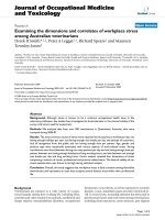
Combining the vertical deposition with the MIMIC
method, we have demonstrated a versatile procedure
of fabricating high-quality stable colloidal crystal chips
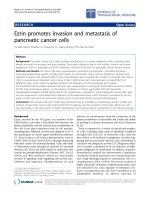
[38, 45]. Figure 1I, II schematically outlines the pro-
cedure. When two substrates were put in contact and
vertically placed in the dispersions of microspheres, the
dispersions were sucked in between them through
capillary force. During the water evaporation, micro-
spheres crystallized between the two substrates from
the top to the bottom along the arrow direction
(Fig. 1I). A convective transportation of microspheres
towards the upper crystallized microspheres was driven
by the continuous flow of the dispersion, which was
caused by the water evaporation and the capillary force
between the substrates. After water evaporated com-
pletely, stable colloidal crystals were formed in be-
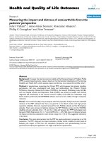
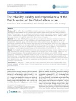
tween the two substrates. Figure 2I shows typical
scanning electron microscopy (SEM) image of the
colloidal crystals obtained by two-substrate vertical
deposition.
The confinement of the two substrates renders col-
loidal crystal chips rather mechanically stable.
Accordingly, we have developed an alternative ap-
proach towards non-spherical colloidal crystals
(NSCCs). First, colloidal crystal chips constructed from
low-cross-linked polystyrene beads were prepared by
two-substrate vertical deposition. Second, these col-
loidal crystal chips were pressed at the temperature of
slightly below the glass transition temperature (Tg) of
the polymer colloids (Fig. 1III). After thermal-press-
ing, polymer beads were transformed into polyhedrons
(quasi rhombic dodecahedrons as illustrated by the
model in Fig. 1IV), and NSCCs were obtained. In our
experiments, heating procedure only made polymer
spheres tend to transform, while the high pressure
Fig. 1 Schematic illustration
of two-substrate vertical
deposition and procedure
used to prepare NSCCs
Fig. 2 SEM images of the
colloidal crystals fabricated
by two-substrate vertical
deposition (I) and of the
NSCCs (II). The inset in (II)
is high magnification SEM
image of the NSCCs
Nanoscale Res Lett (2006) 1:46–56 47
123
would extrude air in the interstices and dominated the
deformation process smoothly and swiftly. Moreover,
the temperature lower than Tg of polymer micro-
spheres prevented colloidal crystals from fusing into
membrane. Figure 2II shows the section SEM image of
the NSCCs, and its inset shows the high magnification
SEM image of the inner layers view at a tilt angle of
45° to the normal of the (111) plane. As compared with
spherical colloidal crystals, the NSCCs should have
different optical properties due to their special sym-
metry, which may be attractive in applications such as
photonic crystals [50].
Colloidal crystals with ordered voids
Combining micro-contact printing (lCP) [52], self-
organization of organic liquid on patterned self-
assembled monolayers (SAMs) [53], and vertical
deposition [27–29], we have developed a simple
method to fabricate ordered voids in a colloidal crys-
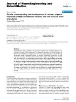
tal film-substrate system [40]. Figure 3 outlines the
procedure used to fabricate ordered voids in the col-
loidal crystal film. Gold-coated substrates were pat-
terned with a hydrophobic SAM of hexadecanethiol
and a hydrophilic SAM of mercaptopropionic acid
by lCP. When the patterned substrates were lowered
through the interface between hexadecane and an
aqueous solution, the hexadecane cannot wet the
hydrophilic regions, while self-organized into droplets
loaded on the hydrophobic regions, to minimize
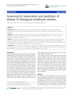
interfacial liquid energies. Figure 4I, III shows optical
photographs of the organic liquid patterns (point and
parallel lines) formed on the patterned gold sub-
strates. Polymer microspheres were deposited on the
hexadecane-patterned gold substrates by vertical
deposition. During the deposition process, the strong
capillary force, formed at the meniscus between the
substrate and the colloidal solution, drove the micro-
spheres to assemble around hexadecane droplets into
3D close-packed arrays. Once the crystallization was
finished, hexadecane evaporated through the intersti-
tial spaces between the spheres, resulting in ordered
microstructures of voids between the crystal films and
the gold substrates. Figure 4II, IV shows SEM images
of colloidal crystal films with point- and line-like voids,
derived from templates shown in Fig. 4I and III,
respectively. These voids are potentially useful as
optical cavities and waveguides for light in photonic
chips. Besides the voids shown in Fig. 4, more complex
microstructures may be produced by rationally
designing the structures of the organic liquid templates.
Patterned colloidal crystals
Applying lift-up soft lithography [63]andlCP to col-
loidal crystallization, we have developed versatile
approaches to patterned colloidal crystals of various
structures. As illustrated in Fig. 5I, a PDMS stamp
with patterned features was brought into contact with
the colloidal crystal film deposited on a silicon sub-
strate. After the sample was heated at 100 °C for 3 h
and the PDMS stamp was carefully peeled away, a
single layer of close-packed microspheres was trans-
ferred to the surface of PDMS stamp and the corre-
sponding pattern was formed on the colloidal crystal
film surface. Figure 6I shows a typical SEM image of
parallel lines of 2D colloidal crystalline arrays fabri-
cated by a one-step lift-up process. We also tried to
Fig. 3 Schematic illustration
of the procedure used to
fabricate ordered voids in the
colloidal crystal films
48 Nanoscale Res Lett (2006) 1:46–56
123
apply this method to prepare microstructures of 3D
colloidal crystalline arrays. Figure 6II shows the
resulting microstructures in a double-layered crystal
film fabricated by a two-step lift-up process. First, a
single layer of the microspheres was selectively
removed, leaving parallel lines in the top layer. Second,
another PDMS stamp with the same patterned feature
was applied to this patterned crystal film in a direction
orthogonal to the initial stamp orientation, under a
high pressure of 1.0 · 10
5
Pa. Ordered squares of
colloidal crystals were formed in the top layer and
ordered squares of voids appeared in the second layer.
This method is versatile not only for patterning the
colloidal crystals on substrates, but also for selectively
creating a single layer of ordered microspheres on the
protruding surface of a PDMS stamp. A stamp with
features of micrometer-sized hemispheres was used to
transfer microsphere arrays in lift-up lithography,
fabricating micrometer-sized hemispheres covered
with hexagonal close-packed (hcp) silica microspheres,
(Fig. 6III). This special structure would be potentially
useful as a model system to develop optical designs
with ultrawide fields-of-view.
Based on lift-up lithography and lCP, we have
succeeded in transferring colloidal crystals intention-
ally [42]. As shown in Fig. 5(II), a thin film of poly-
mer, usually poly(vinyl alcohol) (PVA) was either
spin-coated on planar substrates or dip-coated on
Fig. 4 (I, III) Optical
photographs of the organic
liquid patterns. (II, IV) SEM
images of colloidal crystal
films with point- and line-like
voids derived from templates
shows in (I, III). The inset in
(II) is high magnification
SEM image of the voids in
colloidal crystal films
Fig. 5 Schematic illustration
of lift-up soft lithography (I)
and lCP (II) of colloidal
crystals
Nanoscale Res Lett (2006) 1:46–56 49
123
non-planar substrates. The PDMS stamp coated with
2D colloidal crystal films was brought into contact with
the PVA film. After the sample was heated above Tg
of PVA for a while, the PDMS stamp was peeled off
carefully, and the 2D colloidal crystal films were
transferred onto the substrate. Figure 7I, II shows the
Fig. 6 (I, II) SEM images of
2D and 3D patterned
colloidal crystals fabricated
by lift-up process. (III)3D
AFM image of micrometer-
sized hemisphere covered
with hcp silica microspheres
Fig. 7 (I, II) SEM images of
the patterned 2D colloidal
crystal on planar and non-
planar substrates. (III)
Optical photograph of the
patterned heterogeneous
colloidal crystal using a two-
step lCP procedure. (IV)
High magnification SEM
image of a crossover of two
crystal film lines in (III)
50 Nanoscale Res Lett (2006) 1:46–56
123
SEM images of the patterned 2D colloidal crystals
formed on planar and non-planar substrates. Our
method is versatile not only for patterning colloidal
crystals on both the planar and non-planar substrates,
but also for creating the heterogeneous crystal film. For
example, Fig. 7III shows an optical photograph of the
patterned heterogeneous colloidal crystal constructed
from two different microspheres, which was fabricated
via a two-step lCP procedure. In the first step, a single
layer of close-packed polystyrene (PS) microspheres
was transferred onto a substrate using the procedure
outlined above. Then a silica microsphere-coated
stamp with different relief structure was applied to the
primary patterned colloidal crystal film in a direction
orthogonal to the initial stamp orientation. The lines of
heterogeneous colloidal crystalline arrays in the
resulting pattern show two kinds of uniform colors due
to light diffraction. The high magnification SEM image
(Fig. 7IV) of a crossover of two crystal film lines dis-
plays the heterogeneous structures of this colloidal
crystal: one line is made of 230 nm silica microspheres,
and the other is made of 200 nm PS microspheres.
Non-close-packed arrays of colloidal microspheres
It is well-known that conventional self-assembly
methods could be applied to produce 2D or 3D
ordered arrays of colloidal microspheres. Using etching
techniques [54, 55] or charged spheres [56], non-close-
packed (ncp) arrays with controllable spacing between
spheres can be created. Nonetheless, it is difficult to
obtain lattice structures different from hexagonal
packing. As mentioned in the last part, we have dem-
onstrated a lift-up soft lithography technique to form
2D hcp microsphere arrays on the surface of PDMS
stamp [41]. Based on the solvent-swelling [57] and
mechanical deformation behaviors of PDMS, we can
adjust the lattice structures of these 2D microsphere
arrays [44]. Most importantly, the as-prepared 2D ncp
arrays can be transferred onto the surfaces of solid
Fig. 8 Schematic illustration of the procedure for fabricating 2D
ncp array of microspheres
Fig. 9 SEM images of the
close-packed array of silica
microspheres (I), hexagonal
ncp arrays fabricated by
swelling (II) and ncp
microsphere arrays with new
lattice symmetries resulted
from stretching (III and IV).
Inset in (I) illustrates two
typical crystal lattices of ncp
microsphere arrays obtained
by stretching. Insets in (II, III
and IV) display the Fourier
transforms of the
corresponding images
Nanoscale Res Lett (2006) 1:46–56 51
123
substrates by using a modified lCP transfer technique
[42]. The experiment procedure is illustrated in Fig. 8.
By using the lift-up soft lithography, a single layer of
hcp microspheres were transferred to the surface of
PDMS film, which was subsequently stretched or
swollen with a mixture of toluene and acetone to
transform the hcp arrays into the ncp ones. The 2D ncp
arrays obtained on the deformed PDMS film were
transferred to a PVA-coated substrate by the modi-
fied lCP technique. Figure 9I shows a typical SEM
image of the hcp ordered silica microsphere array.
Figure 9II displays an ordered 2D hexagonal ncp array
of microspheres transferred to a polymer-coated sub-
strate by using a PDMS film swollen with pure toluene.
By stretching the microsphere-coated PDMS elastom-
ers, ncp arrays with new crystal lattices were obtained.
Inset in Fig. 9I schematically illustrates two typical
crystal lattices of the ncp microsphere arrays resulted
from stretching. Figure 9III shows an SEM image of
the quasi-one-dimensional parallel wires of silica
microspheres that were fabricated by stretching the
PDMS film along x-axis by about 163% while main-
taining the length of y-axis. Figure 9IV shows an SEM
image of the square ncp structure formed by stretching
the PDMS film along y-axis by about 166% while
maintaining the length of x-axis. As a result of the
controllable homogeneous macroscopic elongation of
PDMS film, the hcp arrays can be transformed into
various ncp lattices. Although the crystal lattices are
greatly changed, the long-range ordering are essen-
tially preserved in the resulting ncp arrays, which can
be evidenced by Fourier transforms of the corre-
sponding images displayed in the insets.
In brief, using the solvent-swelling and mechanical
deformation behaviors of PDMS elastomers, we have
developed a simple soft lithography technique to fab-
ricate ncp microsphere arrays with designable lattice
structures. This technique provides a simple and flexi-
ble route for creating microlens arrays [56, 58] and
adjustable templates for the systematic study of the
epitaxial growth of 3D colloidal crystals [59, 60], and
for the fabrication of novel nanostructures, such as
ordered arrays of nanoholes [61] or nanodots on vari-
ous substrates.
Application of colloidal crystals as templates
for surface patterning
A number of approaches, involving lCP and soft
lithography [62, 63], self-assembly, and laser-assisted
directed imprinting lithography [64], have been applied
to pattern surfaces. However, to achieve 2D nanopat-
terned SAMs and desired morphologies on various
substrates remains a challenge. Using the colloidal
crystals as templates, we have developed a number of
methods to generate surfaces patterned with different
structures range from nanoscale to micron-scale.
Particularly, we have developed colloidal-crystal-as-
sisted-capillary nanofabrication (CCACN) [45] and
colloidal-crystal-assisted-imprint (CCAIP) [46] tech-
niques, in which we intentionally applied 3D colloidal
crystals in preparing 2D nanostructures on various
substrates.
CCACN approach to 2D nanostructured surface
Figure 10
outlines the procedure of CCACN approach.
In step (I) a solution of polymer or reagents, which
could react with the substrates, was penetrated into the
Fig. 10 Schematic illustration
of the CCACN
52 Nanoscale Res Lett (2006) 1:46–56
123
interstices in colloidal crystal chips obtained by two-
substrate vertical deposition, followed by drying in air.
Steps (II) and (III) show the dewetting or the reaction
of the filling species, solutions with a low and high
concentration, respectively. Steps (IV) and (V) involve
the ultrasonication and rinsing to remove the micro-
sphere templates. Figure 11I, II shows typical 3D AFM
images of PVA nanostructures fabricated by infiltrat-
ing aqueous PVA solution of 10 mg/mL and 40 mg/
mL, respectively.
When we change the spherical colloidal crystal
templates to non-spherical ones, nanostructures with
different symmetry can be fabricated accordingly. For
the NSCC obtained by pressing, there is a flat surface
on the side adhered to the substrate. Insets in Fig 11III,
IV show the morphology of the NSCC surfaces
adhered to the substrates. These two NSCCs are of
different crystalline orientations. Using these NSCCs
as templates in CCACN, 2D nano-networks can be
obtained (Fig. 11III, IV). First, NSCCs were fabricated
between two gold-coated wafers by the method men-
tioned above. Second, we dipped as-prepared NSCCs
chips into a solution of silver enhancer (1:1 A/B), the
solution was sucked into the interstices in the NSCCs.
After reacting for 30 min at room temperature, the
silver enhancer formed silver patterns on the bare
surfaces of the gold substrates, which were not covered
with polymer particles. By removing the polystyrene
particles with toluene, silver structures were left on
gold wafers. Since we can adjust the structures and size
of colloidal crystal chips and the chemical nature of
substrates, our method can be readily to extend to
other materials, opening up a variety of applications in
nanofabrication, nanosensors, microreactors, and the
control of crystallization.
CCAIP approach for mesoscopic structured arrays
and hierachical patterns
Using 3D self-assembled colloidal crystals as masters in
mesoscopic imprint lithography, CCAIP approach is
generally applicable. Figure 12 outlines the CCAIP
procedure for patterning polymer or multilayered
hybrid films. First, the substrates were coated by
polymers or multilayered hybrid films by spin-coating
or chemical vapor deposition (CVD). Second, colloidal
crystals of silica microspheres were formed between
two desired substrates by two-substrate vertical depo-
sition (I). Third, the colloidal crystal chips were
imprinted at a temperature above Tg of the polymer
Fig. 11 (I, II) Typical 3D
AFM images of PVA
nanostructures fabricated by
CCACN. (III, IV) SEM
images of silver nano-
networks on gold substrates
with different symmetries.
Insets in (III) and (IV) show
the SEM images of the non-
spherical templates used to
obtain the nano-networks
shown by corresponding
images
Nanoscale Res Lett (2006) 1:46–56 53
123
(II). Finally, 2D-patterned structures were achieved on
the substrates after the removing of the 3D colloidal
crystals by chemical etching (III) or ultrasonication
(IV).
Figure 13I shows an array of pores in polystyrene
film coating on gold-coated substrate. The pore walls’
thickness is 20–50 nm, their periodicity about 290 nm,
and their depth 120 nm. Figure 13II presents the SEM
image of a patterned surface with hierarchical meso-
scopic hybrid structures. We obtained this complex
patterned surfaces by spin-coating a layer of polymer
film onto a silicon wafer, followed by depositing a gold
film on it, then combining the hybrid-film-coated sili-
con wafer with a patterned PDMS stamp to carry out
the CCAIP procedure. In this case, we removed the 3D
colloidal crystals by ultrasonication, and many micro-
spheres were left on the substrate (as illustrated by
Fig. 12b) generally according to the protruding struc-
ture of PDMS stamp. Although we have not yet
quantified the accuracy in hierarchical registration, it
can be expected to extend to other materials and var-
ious applications in nanofabrication, hierarchical pat-
terns, and hybrid plastic electronics.
Ordered silica microspheres unsymmetrically
coated with Ag nanoparticles and
Ag-nanoparticle-doped polymer voids
The design and preparation of unsymmetrically coated
colloidal particles have been a long-standing challenge
in surface and colloid science [65–69]. Based on the lift-
up soft lithography of colloidal crystals [41], we
developed an alternative way of fabricating ordered
silica microspheres unsymmetrically coated with Ag
nanoparticles by chemical reduction [47]. Taking
advantage of the flexibility of lCP technique [42],
these microsphere arrays can be easily transferred onto
polymer-coated solid substrates and precisely realize a
Fig. 12 Schematic procedure of CCAIP for patterning polymer
or multilayer hybrid films
Fig. 14 Schematic illustration of the procedure used to prepare
ordered silica microspheres unsymmetrically coated with Ag
nanoparticles and Ag-nanoparticle-doped polymer voids
Fig. 13 (I) SEM image of
pore arrays in a polystyrene
film coated on gold substrate.
(II) SEM images of patterned
surfaces with hierarchical
mesoscopic hybrid structures.
The insets are high
magnification SEM images
54 Nanoscale Res Lett (2006) 1:46–56
123
tropism conversion. By etching away the silica micro-
spheres, ordered Ag-nanoparticle-doped polymer
voids are obtained.
Figure 14 outlines the procedure for preparing
ordered silica microspheres unsymmetrically coated
with Ag nanoparticles and Ag-nanoparticle-doped
polymer voids. First, a single layer of close-packed
silica microspheres are transferred onto the surface of
a PDMS stamp by using the lift-up soft lithography
technique. After depositing Ag nanoparticles on the
microspheres by chemical reduction [39], the silica
microspheres are unsymmetrically coated with Ag
nanoparticles, which can be transferred onto another
substrate by a lCP technique. By etching away the
silica microspheres with hydrofluoric acid, ordered Ag-
nanoparticle-doped polymer voids are finally obtained.
Figure 15I is an SEM image of ordered silica micro-
spheres unsymmetrically coated with Ag nanoparticles
on the PDMS stamp. The silica microspheres are uni-
formly coated with Ag nanoparticles and also adopt an
ordered hexagonal array. Due to the uniformity of the
Ag nanoparticles and the ordered arrays of the com-
posite microspheres, these ordered microspheres can
be used as substrates for surface-enhanced Raman
scattering (SERS). Figure 15II is the SEM image of the
ordered Ag-nanoparticle-doped polymer voids after
the silica microspheres are etched away.
Conclusion
In conclusion, we have demonstrated a set of
approaches to fabricate new colloidal crystals with
ordered voids, 2D- or 3D-patterned arrays, composed
of non-spherical polyhedrons, patterned colloidal
crystals on non-planar surfaces, heterogeneous colloi-
dal crystals of different building blocks, and particu-
larly colloidal crystals of non-close-packed colloidal
microspheres. These new colloidal crystals should be of
importance in a wide range of applications, especially
in photonics. Using various colloidal crystals obtained
as templates, several methods have been established to
generate surface patterns with different structures
range from nanoscale to micron-scale. Particularly, we
have put up CCACN and CCAIP techniques, in which
we intentionally applied 3D self-assembled colloidal
crystals in preparing 2D nanostructures on different
substrates. Therefore, our methods listed here should
hold immersed promise in nanofabrication, nanosen-
sing, microreactors, and control of colloidal crystalli-
zation.
Acknowledgments This work is supported by the National
Nature Science Foundation of China (Grant No. 90401020,
20534040 & 200340062) and the program for Changjiang Schol-
ars and Innovative Research Team in University (No. IRT0422).
References
1. O.D. Velev, T.A. Jede, R.F. Lobo, A.M. Lenhoff, Nature
389, 447 (1997)
2. B.T. Holland, C.F. Blandford, A. Stein, Science 281, 538
(1998)
3. J.E.G.J. Wijnhoven, W.L. Vos, Science 281, 802 (1998)
4. A.A. Zakhidov, R.H. Baughman, Z. Iqbal, C. Cui, I. Khay-
rullin, S.O. Dantas, J. Marti, V.G. Ralchenko, Science 282,
897 (1998)
5. S.H. Park, Y. Xia, Adv. Mater. 10, 1045 (1998)
6. Q. Luo, Z. Liu, L. Li, S. Xie, J. Kong, D. Zhao, Adv. Mater.
13, 286 (2001)
7. M.D. Sacks, T.Y. Tseng, J. Am. Ceram. Soc. 67, 526 (1984)
8. P. Calvert, Nature 317, 201 (1985)
9. S.H. Park, Y. Xia, Langmuir 15, 266 (1999)
10. S.Y. Chang, L. Liu, S.A. Asher, J. Am. Chem. Soc. 116, 6739
(1994)
11. J.H. Holtz, S.A. Asher, Nature 389, 829 (1997)
12. J.H. Holtz, J.S.W. Holtz, C.H. Munro, S.A. Asher, Anal.
Chem. 70, 780 (1998)
13. O.D. Velev, E.W. Kaler, Langmuir 15, 3693 (1999)
14. G.A. Ozin, S.M. Yang, Adv. Funct. Mater. 11, 95 (2001)
15. S.M. Yang, H. Mguez, G.A. Ozin, Adv. Funct. Mater. 12, 425
(2002)
16. R. Mayoral, J. Requena, J.S. Moya, C. Lopez, A. Citas,
H. Miguez, F. Meseguer, L. Vazquez, M. Holgado,
A. Blanco, Adv. Mater. 9, 257 (1997)
Fig. 15 (I) SEM image of
ordered silica microspheres
unsymmetrically coated with
Ag nanoparticles. (II) SEM
image of the ordered Ag-
nanoparticle-doped polymer
voids. The insets are high
magnification SEM images
Nanoscale Res Lett (2006) 1:46–56 55
123
17. H. Miguez, F. Meseguer, C. Lopez, A. Mifsud, J.S. Moya, L.
Vazquez, Langmuir 13, 6009 (1997)
18. L.N. Donselaar, A.P. Philipse, J. Suurmond, Langmuir 13,
6018 (1997)
19. N. Ise, Angew. Chem. Int. ed. Engl. 25, 323 (1986)
20. H.B. Sunkara,. J.M. Jethmalani, W.T. Ford, Chem. Mater. 6,
362 (1994)
21. A.E. Larsen, D.G. Grier, Nature 385, 230 (1997)
22. N.D. Denkov, O.D. Velev, P.A. Kralchevsky, I.B. Ivanov,
H. Yoshimura, K. Nagayama, Langmuir 8, 3183 (1992)
23. C.D. Dushkin, K. Nagayama, T. Miwa, P.A. Kralchevsky,
Langmuir 9, 3695 (1993)
24. A.S. Dimitrov, K. Nagayama, Langmuir 12, 1303 (1996)
25. S. Rakers, L.F. Chi, H. Fuchs, Langmuir 13, 7121 (1997)
26. S.H. Park, D. Qin, Y. Xia, Adv. Mater. 10, 1028 (1998)
27. P. Jiang, J.F. Bertone, K.S. Hwang, V.L. Colvin, Chem.
Mater. 11, 2132 (1999)
28. Y.A. Vlasov, X. Bo, J.C. Sturm, D.J. Norris, Nature 414, 289
(2001)
29. Z.Z. Gu, O. Sato, A. Fujishima, Chem. Mater. 14, 760 (2002)
30. M. Trau, N. Yao, E. Kim, Y. Xia, G.M. Whitesides,
I.A. Aksay, Nature 390, 674 (1997)
31. X. Chen, Z.C. Cui, Z.M. Chen, K. Zhang, G. Lu, G. Zhang,
B. Yang, Polymer 43, 4147 (2002)
32. X. Chen, Z.M. Chen, B. Yang, G. Zhang, J.C. Shen, J. Col-
loid Interface Sci. 269, 79 (2004)
33. X. Chen, Z.M. Chen, G. Lu, W.F. Bu, B. Yang, J. Colloid
Interface Sci. 264, 266 (2003)
34. K. Zhang, H.T. Chen, X. Chen, Z.M. Chen, Z.C. Cui,
B. Yang Macromol. Mater. Eng. 4, 380 (2003)
35. K. Zhang, X.H. Zhang, H.T. Chen, X. Chen, L.L. Zheng,
J.H. Zhang, B. Yang, Langmuir 20, 11312 (2004)
36. X. Chen, Z.T. Yu, J.S. Chen, B. Yang, Mater. Lett. 58, 384
(2004)
37. T.Y. Cui, J.H. Zhang, J.Y. Wang, F. Cui, W. Chen, Z. Wang,
K. Zhang, B. Yang, Adv. Funct. Mater. 15, 481 (2005)
38. X. Chen, Z.Q. Sun, Z.M. Chen, K. Zhang, B. Yang, Chinese
Sci. Bull. 50, 321 (2005)
39. Z.M. Chen, X. Chen, L.L. Zheng, T. Gang, T.Y. Cui,
K. Zhang, B. Yang, J. Colloid Interface Sci. 285, 146 (2005)
40. G. Lu, X. Chen, J.M. Yao, W. Li, G. Zhang, D.Y. Zhao,
B. Yang, J.C. Shen, Adv. Mater. 14, 1799 (2002)
41. J.M. Yao, X. Yan, G. Lu, K. Zhang, X. Chen, L. Jiang,
B. Yang, Adv. Mater. 16, 81 (2004)
42. X. Yan, J.M. Yao, G. Lu, X. Chen, K. Zhang, B. Yang,
J. Am. Chem. Soc. 126, 10510 (2004)
43. Z.Q. Sun, X. Chen, J.H. Zhang, Z.M. Chen, K. Zhang,
X. Yan, Y.F. Wang, W.Z. Yu, B. Yang, Langmuir 21
, 8987
(2005)
44. X. Yan, J.M. Yao, G. Lu, X. Li, J.H. Zhang, K. Han,
B. Yang, J. Am. Chem. Soc. 127, 7688 (2005)
45. X. Chen, Z.M. Chen, N. Fu, G. Lu, B. Yang, Adv. Mater. 15,
1413 (2003)
46. X. Chen, Z.Q. Sun, L.L. Zheng, Z.M. Chen, Y.Y. Wang, N.
Fu, K. Zhang, X. Yan, H. Liu, L. Jiang, B. Yang, Adv. Mater.
16, 1632 (2004)
47. Z.M. Chen, T. Gang, X. Yan, X. Li, J.H. Zhang, Y.F. Wang,
X. Chen, Z.Q. Sun, K. Zhang, B. Zhao, B. Yang, Adv. Mater.
18, 924 (2006)
48. S. John, Phys. Rev. Lett. 58, 2486 (1987)
49. E. Yablonovitch, Phys. Rev. Lett. 58, 2059 (1987)
50. Y. Xia, B. Gates, Y. Yin, Y. Lu, Adv. Mater. 12, 693 (2000)
51. J.M. Weissman, H.B. Sunkara, A.S. Tse, S.A. Asher, Science
274, 959 (1996)
52. A. Kumar, H. Biebuyck, G.M. Whitesides, Langmuir 10,
1498 (1994)
53. H.A. Biebuyck, G.M. Whitesides, Langmuir 10, 2790 (1994)
54. R. Fenollosa, F. Meseguer, Adv. Mater. 15, 1282 (2003)
55. B.J.Y. Tan, C.H. Sow, K.Y. Lim, F.C. Cheong, G.L. Chong,
A.T. S. Wee, C.K. Ong, J. Phys. Chem. B 108, 18575 (2004)
56. O.J. Cayre, V.N. Paunov, J. Mater. Chem. 14, 3300 (2004)
57. L.C. DeBolt, J.E. Mark, Macromolecules 20, 2369 (1987)
58. Y. Lu, Y. Yin, Y. Xia, Adv. Mater. 13, 34 (2001)
59. A. van Blaaderen, R. Ruel, P. Wiltzius, Nature 385, 321
(1997)
60. K.P. Velikov, C.G. Christova, R.P. A. Dullens, A. van Bla-
aderen, Science 296, 106 (2002)
61. P. Jiang, M.J. McFarland, J. Am. Chem. Soc. 127, 3710
(2005)
62. Y.N. Xia, G.M. Whitesides, Angew. Chem. Int. Ed. 37, 550
(1998)
63. Y.N. Xia, J.A. Rogers, K.E. Paul, G.M. Whitesides, Chem.
Rev. 99, 1823 (1999)
64. S.Y. Chou, C. Keimel, J. Gu, Nature 417, 853 (2002)
65. Y. Lu, H. Xiong, X.C. Jiang, Y.N. Xia, J. Am. Chem. Soc. 25,
12724 (2003)
66. J. Choi, Y.H. Zhao, D.Y. Zhang, S. Chien, Y.H. Lo, Nano
Lett. 3, 995 (2003)
67. H. Takei, N. Shimizu, Langmuir 13, 1865 (1997)
68. K. Fujimoto, K. Nakahama, M. Shidara, K. Kawaguchi,
Langmuir 15, 4630 (1999)
69. L. Petit, E. Sellier, E. Duguet, S. Ravaine, C. Mingotaud,
J. Mater. Chem. 10, 253 (2000)
56 Nanoscale Res Lett (2006) 1:46–56
123