Báo cáo hóa học: " FPGA Dynamic Power Minimization through Placement and Routing Constraints" doc
Bạn đang xem bản rút gọn của tài liệu. Xem và tải ngay bản đầy đủ của tài liệu tại đây (1.88 MB, 10 trang )
Hindawi Publishing Corporation
EURASIP Journal on Embedded Systems
Volume 2006, Article ID 31605, Pages 1–10
DOI 10.1155/ES/2006/31605
FPGA Dynamic Power Minimization through Placement and
Routing Constraints
Li Wang, Matthew French, Azadeh Davoodi, and Deepak Agarwal
Information Sciences Institute, University of Southern California, Arlington, VA 22203, USA
Received 15 December 2005; Accepted 18 April 2006
Field-programmable gate arrays (FPGAs) are p ervasive in embedded systems requiring low-power utilization. A novel power op-
timization methodology for reducing the dynamic power consumed by the routing of FPGA circuits by modify ing the constraints
applied to existing commercial tool sets is presented. The power optimization techniques influence commercial FPGA Place and
Route (PAR) tools by translating power goals into standard throughput and placement-based constraints. The Low-Power Intel-
ligent Tool Environment (LITE) is presented, which was developed to support the exper imentation of power models and power
optimization algorithms. The generated constraints seek to implement one of four power optimization approaches: slack mini-
mization, clock tree paring, N-terminal net colocation, and area minimization. In an experimental study, we optimize dynamic
power of circuits mapped into 0.12 µm Xilinx Virtex-II FPGAs. Results show that several optimization algorithms can be combined
on a single design, and power is reduced by up to 19.4%, with an average power savings of 10.2%.
Copyright © 2006 Li Wang et al. This is an open access article distributed under the Creative Commons Attribution License, which
permits unrestricted use, distribution, and reproduction in any medium, provided the original work is properly cited.
1. INTRODUCTION
Field-programmable gate arrays (FPGAs) now handle most
digital signal processing functions in an embedded plat-
form.However,manyembeddedplatforms,suchashand-
held devices, distributed sensors, and satellites, demand low
power in order to increase their functional lifetime. While
SRAM-based FPGAs have a short design cycle, steadily de-
creasing cost, and growing performance, power consump-
tion remains a concern [1]. The trend from one FPGA de-
vice family to another is the number of configurable logic
blocks (CLBs) and maximum operating frequency scale ex-
ponentially, while corresponding decreases in operating volt-
age have been much slower to arrive, resulting in an expo-
nentially increasing maximum power consumption per de-
vice [2]. Therefore, power must be considered at every level,
from VLSI issues such as transistor layout and leakage cur-
rent, to the software that determines how efficiently a user’s
design is implemented on an FPGA.
There have been many FPGA power reduction ap-
proaches addressing different design levels. Several tech-
niques for low power FPGA design have appeared in litera-
ture addressing the VLSI design of an FPGA [2–4]. Research
has also considered var ious synthesis-level power optimiza-
tions, such as technology mapping to LUT-based FPGAs
techniques [5] or reducing glitching power through pipelin-
ing [6]. It has also been shown that power can be addressed
in the suite of computer-aided design ( CAD) algorithms that
place and route an end user’s circuit onto the FPGA fabric
[7].
For our research, we are considering techniques that yield
immediate results on today’s devices and interoperate with
commercial off-the-shelf (COTS) CAD tools. We further re-
strict our focus to techniques that do not modify the func-
tional behavior of the circuit and guarantee that the user’s
original timing, or throughput, constraints are met. In this
paper, we propose a novel power optimization methodology
that converts power optimization goals into constraints com-
pliant with throughput-based COTS PAR tools, minimizing
the power consumption of a desig n’s routing interconnect.
In today’s FPGAs about 50–70% of total power is dis-
sipated in the interconnection network [8]. The dynamic
powerofnetsischaracterizedby
P
dynamic
=
i
C
i
× F
i
× V
2
,(1)
where C
i
and F
i
are the capacitance and average toggle rate
of the ith net, and V is the internal voltage. For a given net,
the dynamic power can be reduced by diminishing its capac-
itance, or length. Nets with high toggle ra tes and/or high ca-
pacitance therefore are good potential targets for decreasing
the overall power and serve as the motivation of the power
optimization schemes presented.
2 EURASIP Journal on Embedded Systems
In this work, we first introduce the Low-Power Intelligent
Tool Environment (LITE) created for this research. This en-
vironment allows the development and experimentation of
power models, tracking dynamic power consumption during
simulation, and power estimation at the synthesis level, while
providing an infr astructure to rapidly design and execute
new power optimization algorithms. Using LITE, four power
optimization approaches were created and implemented that
generate constraints compliant with the COTS Xilinx PAR
tools.
The rest of the paper is organized as follows. In Section 2,
we int roduce the relevant background on the Xilinx Virtex-
II FPGA microarchitecture as it pertains to routing inter-
connects and power consumption. Section 3 addresses the
software, first describing the Xilinx CAD tool flow and then
the infrastructure of the Low-Power Intelligent Tool Envi-
ronment (LITE). Section 4 introduces the power optimiza-
tion algorithms and their experimental results. In Section 5,
the results of combining the power optimization methods
are presented. In Section 6, we extend our software results
to a hardware testbed and validate our approach. Finally,
Section 7 concludes the paper.
2. FPGA DEVICE POWER CHARACTERISTICS
In order to create efficient power optimization algorithms,
the underlying FPGA architecture must be well understood.
Though the techniques presented here work for a variety of
FPGA microarchitectures, we will limit our focus in this pa-
per to the Xilinx Virtex-II FPGA. The Virtex-II FPGA devices
are comprised of input/output blocks (IOBs), located on the
edges of FPGA chips, and configurable logic blocks (CLBs)
organized as a two-dimensional array inside the ring of IOBs
[9]. Each CLB includes four slices and an interconnect block.
Slices provide functional elements for combinational and
synchronous logic which can be configured as ROMs, LUTs,
or SRLs, flip-flops, or other circuitry. The logic of a user’s cir-
cuit will be considered static after synthesis and capacitance
information of each microarchitecture feature can be found
in literature [8] or in software by exporting information from
Xilinx XPower power analysis tool.
In Virtex-II FPGAs, CLBs connect to the global routing
matrix through the interconnect fabric. Global routing re-
sources are comprised of 4 types of lines: long lines, hex lines,
double lines, and direct connect lines, in the order of their
length. Interconnect capacitance can also be found by ex-
porting results from the Xilinx XPower tool. It is important
to note that a net in a user’s circuit may have any combina-
tion of routing, from carry-chains and internal CLB routing
with minimal capacitance, to se veral vertical and horizontal
hops along longer interconnect routes. A quick glance at the
interconnect capacitance in Table 1 shows that a reduction
by only one interconnect length can yield about a 30% re-
ductionincapacitance.
The clocking infrastru cture is also critical to consider
when optimizing power. With 100% toggle rates and ex-
tremely high fanouts, these nets typically consume the most
power in a design, even with dedicated clocking lines. The
Clock
quadrant
NW
NE
SW SE
Clock trunk
Clock branch
Clock region
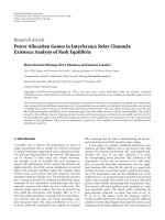
Figure 1: Clock tree and clock regions in XC2V6000 FPGA.
Table 1: Interconnect capacitance.
Interconnect line Capacitance (pF)
Direct line 9.4
Double line 13.2
Hex line 18.4
Long line 26.1
Virtex-II architecture supports 16 clocks, and 8 global clocks
canbeusedineachquadrantofthedevice.Ineachquad-
rant, clocks are organized in clock regions. Figure 1 depicts
the clock tree and clock regions in the XC2V6000 FPGA de-
vice.
Although we are focusing on the Virtex-II architecture,
the algorithms presented here can be adapted to other archi-
tectures as well, as long as cost tables such as those in Table 1
are adjusted to account for minor architecture differences.
3. SOFTWARE INFRASTRUCTURE
This section discusses the software infrastructure developed
to rapidly analyze FPGA power consumption and implement
power optimization algorithms. As the developed tools inter-
operate with the COTS CAD tool flow, the Xilinx PAR tools
will be discussed first with respect to power and the Low-
Power Intelligent Tool Environment (LITE) is described af-
terwards. Finally, the experiment framework and validation
methodology are presented.
3.1. Xilinx tool flows
The Xilinx tool flow of design implementation includes the
following steps [10].
(i) Translate, which merges the incoming netlists and con-
straints into a Xilinx design file.
(ii) Map, which fits the design into the available resources
on the target device.
(iii) Place and Route, which places and routes the design to
the timing constraints.
After Place and Route, the resulting netlist can be in-
put into the Xilinx XPower tool to create a detailed power
consumption report. HDL models can be created after PAR
for back-annotated simulation to increase the precision of
Li Wang et al. 3
Placement and routing
NGD
HDL
Synthesis
EDIF
EDIF
parser
JHDL
Simulator
Power
calibration
Power
modeling
Power
optimization
UCF
Power
optimized
UCF
XDL
XPower
LITE component
JHDL tool
COTS tool
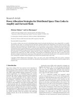
Figure 2: LITE tool flow.
XPower reports. All experiments were run using the Xilinx
ISE 6.3 toolset.
3.2. LITE tool flow
The Low-Power Intelligent Tool Environment (LITE) was
created to facilitate power research by elevating power to a
first-order design parameter. It uses calibration, modeling,
and estimation techniques to provide automated power esti-
mation at the higher, logic-based EDIF level, where it is eas-
ier for a circuit designer to relate the analysis back to their
HDL input. In this work, LITE is expanded to incorporate
power optimization algorithms that generate UCF file con-
straints to be passed along to the Xilinx PAR tools as shown
in Figure 2.
LITE consists of three components designed to expand
the existing COTS power analysis capabilities and experi-
ment with power optimization algorithms: power calibra-
tion, power modeling, and power constra int genera tion. The
LITE tool infrastructure is an extension of the JHDL envi-
ronment. As presented in [11], the JHDL environment pro-
vides a high-level tool suite for querying circuit components,
running simulations, and tracking signal transitions. LITE
builds upon these capabilities to add knowledge about circuit
component and interconnect capacitance, monitor a circuit’s
power consumption during simulation, sort the most power
intensive modules within a circuit, and plot various power
consumption metrics of the desig n. A separate EDIF import
tool was developed that enables FPGA designs generated by
any 3rd party synthesis tool to be imported into LITE. Simu-
lation results can be obtained by either importing a VCD file
or writing a JHDL test bench.
The power calibration component interacts with the Xil-
inx CAD tools to extract the relevant parameters for power
modeling: capacitance, toggle rates, fanout, and power. Xil-
inx XPower reports contain detailed analysis of placed and
routed circuits’ power characteristics, and this information
canbeimportedtoLITEtoobtainthecapacitancevaluesof
every microarchitectural component, logic element, and in-
terconnect. LITE can then use this information to track and
display dynamic power consumption during simulation, or
use these values as device power libraries for post-synthesis
power modeling and estimation.
The power modeling component allows detailed power
analysis of a user’s circuit both at the post-synthesis level
and the placed and routed level. Post-synthesis power mod-
eling is achieved by combining known logic component ca-
pacitance values with routing interconnect length projection
techniques developed in [11]. Exact routing capacitances
cannot be known until PAR has been completed, however
these estimation models are extremely useful in pinpointing
power consumption hot spots early on in the design flow and
prioritizing nets for power optimization during the PAR pro-
cess.
By leveraging the JHDL/EDIF infrastructure, this tool
suite also enables users to import their designs into the LITE
environment, run simulations, track signal transition rates
and power consumption over time, as in Figure 3,sorthi-
erarchy modules by power consumption, and cross-probe
power overlays with the schematic and waveform viewers
inherent to JHDL. Simulations and power analysis can be
performed at either the post-synthesis or placed and routed
netlist level and allows the direct comparison of the syn-
thesized circuit power against it’s placed and routed netlist
power.
The power optimization component utilizes the output
of the power analysis component to apply the power opti-
mization techniques discussed in Section 4.Asmentioned
earlier, the power optimization techniques in LITE do not
modify design logic, but rather feed additional constraints to
the PAR tools such that the existing PAR algorithms can still
meet a user’s throughput specifications while also reducing
power. To support this, the power optimization component
is capable of inspecting the area, resources, and size of the tar-
geted FPGA device and the user’s circuit, reads in any existing
UCF file constraints, and prioritizes the original constraints.
4 EURASIP Journal on Embedded Systems
Table 2: Benchmark circuits.
Design Part number Original timing (MHz) Signal power (%) Logic power (%) Clock power (%) Baseline power (mW)
CRC XC2V80 16 28 42 30 31
FM XC2V250 55 43 45 12 102
VGA XC2V250
125
18 39 43 138
133.3
USBF XC2V500
238
33 30 37 82
105
PCI XC2V1000 100 10 33 57 39
Conv XC2V1000 66 23 55 22 163
DES3 XC2V2000 100 43 21 36 139
Mem XC2V6000 83 8 59 33 643
S1 XC2V6000
160
12 10 78 251
40
180
75
33
S2 XC2V6000
33
9 12 79 1020
250
100
Figure 3: LITE simulation.
3.3. Experimental framework
The methodology for power optimization and power verifi-
cation can also be seen in Figure 2.Toperformpoweropti-
mization, a user imports its design using the EDIF parser,
generates a power simulation using the LITE power mod-
eling component, and then generates a new UCF file using
the LITE power optimization component. The original, un-
altered EDIF file can then be fed through the Xilinx tools us-
ing the new constraints file. To measure the results, we use
the Xilinx XPower tool with placed and routed netlists and
the same value change dump (VCD) simulation data used as
inputs in the LITE power simulation stage.
In order to verify the developed power optimization al-
gorithms, a test suite of ten circuit benchmarks was utilized,
listed in Tab le 2. This suite represents a fairly wide taxon-
omy of applications, from glue logic (Mem) to cores (CRC,
FM, VGA, USBF, PCI, and DES3) to end-to-end applica-
tions (Conv, S1, and S2), spanning a wide range of device
sizes. Each circuit is mapped into the smallest device pos-
sible, such that underutilization does not skew results. All
designs also had UCF files specify ing I/O pin locations and
minimum clocking requirements, shown in the 3rd column.
Multiple clocks are represented by multiple entries. Table 2
also shows the breakout of power consumed by signal, logic,
and clock elements and reveals that there is a mix of clock
dominant, sig nal dominant, and logic dominant designs. In
the final column, the baseline power, the internal dynamic
power of each circuit as reported by XPower is shown, that is,
the sum of the dynamic power consumed by logic elements,
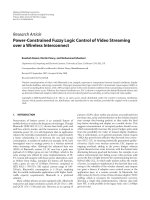
clock nets, and signal nets. Figure 4 shows the slice/IOB uti-
lizations of these designs. Slice occupation r anges from 14%
to 86%, and IOB occupation from 11% to 90%, so there is a
fair representation of I/O bound as well as compute resource
bound circuits.
It should be noted that we have spot checked our re-
sults on hardware as well. Our power measurement testbed,
shown in Figure 5, is comprised of a PCI-DAS1200 ADC
which samples the current sensors connected to the isolated
internal voltage supply lines on an Osiris board’s XC2V6000
device and provides a resolution 2.7 mA. While actual power
consumption was difficult to verify due to variables such as
room temperature, device fabrication variances, and con-
servatism inherent in XPower’s capacitance reporting, the
Li Wang et al. 5
Slice/IOB occupancies
100
80
60
40
20
0
Utilization (%)
CRC FM VGA USBF PCI Conv DES3 Mem S1 S2
Slice usage
IO usage
Figure 4: Benchmarks slice/IOB utilization.
Osiris Virtex-II
board (target)
Power monitoring
extender card
16 bit,
300 KHz
A/D board
CPU running A/D
and target API
software
Signal connector
box (voltages
and triggers)
Figure 5: Power measurement testbed.
percentage power reduction between the optimized and
baseline versions remained constant between XPower soft-
ware reports and hardware measurements in experimental
testing.
4. POWER OPTIMIZATION TECHNIQUES
The power optimization techniques developed center around
the theme of creating timing and placement constraints that
interoperate with existing COTS PAR tools in order to pre-
serve a user’s throughput specifications while also reducing
power consumption. The timing and placement constraints
influence the COTS tools to use shorter, lower capacitance
interconnects. In this paper we provide an overview of four
power optimization techniques that each utilizes a different
constraint type to enact power optimization. The following
subsections explain each technique and present the experi-
mental results achieved.
4.1. Clock tree paring
For our first technique, we will focus on trying to reduce the
amount of power utilized by the clock nets. As Table 2 shows,
even though these nets utilize dedicated, specialized circuitry
within the FPGA, these few nets can contribute with 12% to
79% of the overall power consumption of a design. This is
due to the inherent high toggle rate, high fanout to hundreds
or thousands of synchronous logic elements, and long inter-
connects that span a data path from input to output often
across the entire device.
NW
NE
SW SE
Trunk s w itch
Branch switch
Leaf switch
Figure 6: Clock net switch types.
The clock tree paring algorithm targets the clock power
by utilizing placement constraints to minimize the size of the
clock net tree utilized. As introduced in Section 2, in the Xil-
inx Virtex-II FPGAs, clock nets are distributed on dedicated
routing resources. Through FPGA editor and experimenta-
tion, we observe that clock network is like a tree, with the
main trunk traveling north to south in the middle of the chip,
and branches extending west and east into clock regions. The
number of clock regions varies depending on the size of the
device. The clock tree is gated such that completely unused
branches of the tree are effectively turned off. Therefore by
placing logic closer together, clocking power can be reduced
by gating more of the branches of the clock t ree.
From our analysis, we found that there were three types
of gating switches, shown in Figure 6, which we will call
the tr unk switch, branch switch, and leaf switch. The trunk
switch is located at the center of the chip. This type of switch
is used for turning on or off the upper- or lower-half of the
main clock trunks. When a clock net comes into the chip
from an input port or digital clock manager (DCM), it goes
to the center of the switch-fabric to be routed to the north,
or south, or both. Figure 7(a) shows two clock nets as the
examples: the clock net on the left is switched to both the
upper- and lower-half of the chip. The clock net on the right
is switched to the upper-part of the chip only. Figure 7(b)
depicts a branch sw itch. Each Virtex-II has multiple branch
switches, and the number varies depending on the size of the
device. The switches are located on the path of the main clock
trunks. They are responsible for transmitting the clock sig-
nals to the clock regions. The clock wire shown in Figure 7(b)
travels to both the left and r ight. The leaf switch is depicted
in Figure 7(c). As shown in Figure 7(d), a clock net in the
clock region includes a major branch and many subbranches
that connect to slices. The leaf switch turns on/off these
subbranches. By placing the flip-flops closer to each other,
clocking power can be reduced by leaving more branch/sub-
branch turned off.
The clock tree paring algorithm analyzes a user’s cir-
cuit, computes a minimum bound to contain all the logic
associated with a clock net, and generates area constraints
to specify where the associated clock logic may be placed.
The area constraint is rectangular, stretching north to south
around the clock main tr u nk. The size of the area is pro-
portional to a clock’s fanout. For multiple clock cases, the
LITE power analysis component is used to prioritize clocks
with higher-power consumption and place them closer to
6 EURASIP Journal on Embedded Systems
(a) (b) (c) (d)
Figure 7: (a) Trunk switch; (b) branch switch; (c) leaf switch; (d) clock net connected w ith FFs within a clock region.
Figure 8: Clock area constraints.
Original
Optimized
Figure 9: Clock area optimization in S1.
the clock trunk, as depicted in Figure 8. It should be noted
that the clock groups do not have to be placed radially to the
main trunk to save power. Clock power savings, especially
in larger designs, come from clustering groups of flip-flops
to minimize the number of leaf switches that are activated.
In the cases that I/O timing is critical, flip-flop clusters can
be placed between the I/O pins and a central flip-flop mass
about the clock trunk, to pipeline and better preserve timing
constraints while also minimizing power. Figure 9 shows an
illustrative example of the distributions of one of the clock
trees in S1 before and after the clock optimization.
Table 3 shows the results for clock tree paring power op-
timization. It is interesting to note that even though the sig-
nal power increases in several cases, the clock power savings
Table 3: Clock tree paring results.
Design
Signal
power
reduction
Logic
power
reduction
Clock
power
reduction
Tot a l
power
reduction
CRC 3.6% 0.0% 16.4% 5.9%
FM
−3.0% 0.0% 36.0% 2.9%
VGA
6.4% 0.0% 26.5% 12.5%
USBF
2.1% 0.0% 26.8% 10.7%
PCI
−5.1% 0.0% 34.2% 18.7%
Conv
4.0% 0.0% 18.2% 4.9%
DES3
−4.0% 0.0% 29.2% 8.6%
Mem
−11.2% 0.0% 5.1% 0.7%
S1
−59.9% 0.0% 11.1% 10.7%
S2
−13.8% −0.1% 28.7% 19.4%
are dominate and almost all benchmarks show significant
overall power improvement by using this approach. As can
be expected, the test circuits not responding as well to this
approach (Mem, F M, Conv, and CRC) are considered logic
power dominant designs according to Ta ble 2. The clock
power dominant designs (S2, PCI, VGA, S1, and USBF) are
much more responsive. It should also be noted that though
Figure 9 depicts a circuit with low device utilization for il-
lustrative purposes, the efficacy of this technique is more a
function of a circuit being clock power dominant than high-
or low-logic utilization. For example, S2, a clock power dom-
inant circuit, achieves the most significant power reduction
with a more than 80% device utilization, while Mem, the
lowest device utilization circuit in our test suite, yields the
least significant results.
4.2. N-terminal net colocation
N-terminal net colocation power optimization is targeted to
reduce the power consumed by signal nets. “Terminal” is
defined as the sum of the fanin and fanout of a net. For a
simplified case, a 2-terminal net is a net with a single fanout.
N-terminal net colocation restricts net terminals to be placed
in adjacent slices. As depicted in Figure 10, net terminals are
grouped in pairs, and for each pair, a constraint is used to
restrict the two terminals to be located close to each other,
and thus reducing the signal net length and power. From our
Li Wang et al. 7
Figure 10: N-terminal placement.
LITE calibration and analysis studies, we found that the Xil-
inx Virtex-II architecture has an east-west bias, meaning that
direct connection interconnected in the east-west direction
has less capacitance than direct connections in the north-
south direction, sometimes by a factor of up to 50%. So,
this algorithm is further enhanced to take advantage of this
particular microarchitecture design by prioritizing east-to-
west relative placement constraints. This algorithm can be
updated to reflect other FPGA architecture features as well.
The nets are sorted and prioritized by power consumption
based on simulations using the LITE power analysis environ-
ment to target high-capacitance and high toggle rate nets. In
high fanout cases where nets may belong to multiple terminal
groups, only the highest priority constraint is created.
Initial experimentation showed that this technique
worked well on some nets, however some nets that would
naturally be mapped by the COTS PAR tools to low capaci-
tance lines such as carry chains and internal slice nets were
now being routed on higher capacitance routing intercon-
nect lines due to the constraints. To avoid this, the algorithm
was enhanced to analyze the circuits and selectively avoid
putting constraints on certain nets. Several rules were devel-
oped to avoid overconstraining the designs as follows.
(i) Avoid nets that are a part of shift registers as the Xil-
inx slice contains low capacitance, dedicated connec-
tion between shift registers that are naturally used by
the PAR tools.
(ii) Avoid nets that are a part of carry-chains. The Virtex-II
architecture uses dedicated low capacitance carry logic
to cascade function generators and provide fast arith-
metic addition and subtraction.
(iii) Avoid nets that are mapped internally to slices as these
are also low capacitance routes. These nets can be iden-
tified as those between look-up tables (LUTs) and mul-
tiplexers, and between LUTs and inverters.
The results for the N-terminal net colocation algor ithm
are depicted in Tabl e 4. Here, we see that the overall power
savings is negligible and in a few cases actually becomes
worse. The nonzero values in the logic power reduction col-
umn show that in some cases slices are being packed more ef-
ficiently as desired, however in some designs the N-terminal
approach causes ripple effects in unconstrained nets, caus-
ing more slices to be utilized. While the constrained nets are
reduced, other nets belonging to multiple terminal groups
may be bumped out of internal slice mappings. Comparing
Table 4: N-terminal placement results.
Design
Signal
power
reduction
Logic
power
reduction
Clock
power
reduction
Tot a l
power
reduction
CRC −9.8% 0.0% 0.0% −2.9%
FM
−0.9% −0.5% 1.6% −0.4%
VGA
1.8% 0.2% 0.6% 0.7%
USBF
−9.2% 0.4% −4.2% −4.5%
PCI
2.6% 0.1% −6.8% −3.8%
Conv
1.6% 0.0% −3.4% −0.4%
DES3
1.2% 0.0% −3.3% −0.7%
Mem
9.1% 0.0% −1.8% 0.4%
S1
−10.1% 0.3% −0.5% −0.6%
S2
−1.6% −1.4% 1.6% 1.0%
the signal power, clock power, and total power columns is in-
sightful as well. For a few circuits, CRC, USBF, and S1, there is
a significant reduction in signal power. Closer inspection re-
vealed that these circuits had relatively few high fanout nets.
In all cases however, clock power is still dominating and is
the main influence on total power.
4.3. Area minimization
Another approach to reducing signal power was area mini-
mization. The area minimization power optimization tech-
nique is based on the observation that routing interconnect
lengths highly depend on the placement of components. By
prioritizing the location in favor of power, high capacitance
signal lines with high fanout or high transition rates can be
grouped together to minimize the power consumed on long
interconnects. Constraining the area also has the added affect
of trimming the clock tree; however in this case the total area
is constrained and clock tree pruning is a residual affect.
This technique is expected to work well on circuits that
underutilize the logic available on the chip due to I/O bound
designs or poor device size selection. In these designs, the
COTS PAR tools place the circuits loosely over the whole
chip, doing the minimum to meet the user’s timing require-
ments, as it was designed to do. This behavior however causes
longer connection wires and hence increases the total net
power. By using area minimization constraints, a design is
compacted more tightly in a given area of a chip. Net lengths
are shortened and thus power is saved. In an effort to bal-
ance the north-south bias of the clock trunk with the east-
west bias of the direct connect signal wires, a rectangular area
placed at the center of a chip, with sides proportional to the
chip dimensions, is utilized. The size of the area is estimated
by analyzing and computing the slice count that each design
element needs.
Figure 11 shows an example of the results. On the left-
hand side, the circuit is placed loosely over the chip. After
using the area minimization power optimization, the circuit
is tightly located in an area at the center. It is worth mention-
ing that eventhough area minimization may have the same
effect on the placement of logic components as clock power
8 EURASIP Journal on Embedded Systems
Original Optimized
Figure 11: Area minimization in VGA.
optimization does, it utilizes different constraints. The clock
tree paring technique constrains the clock routing area, influ-
encing the placement of all the logic elements driven by the
clock. The area minimization technique explicitly restricts
the placement of all components, clocked or nonclocked.
The results of area minimization approach are shown in
Table 5, with all circuits showing a positive power reduction.
On closer examination the power savings mostly come due
to clock power reductions, due to residual clock tree mini-
mization effects similar to those developed in the clock tree
paring technique. This technique was unable to be used on
the S2 circuit, as this design occupies 87% of an XC2V6000
device and the area cannot be further minimized.
4.4. Slack minimization
Finally, the slack minimization technique seeks to optimize
the power on signal nets by tightening timing constraints
on power critical nets. The slack minimization algorithm as-
sumes that the PAR tools wil l leave each net at or just under
the user’s specified timing requirements, in many cases leav-
ing slack, or extra net length that could be further tightened
to reduce capacitance. For this algorithm slack is defined as
Slack
= T
Spec
− T
Logic
− T
min wr
,(2)
where T
Spec
is the user’s timing specification, T
Logic
is the tim-
ing delay of any combinatorial logic in between flip-flops on
the net, and T
min wr
is the minimal wire timing delay. For ex-
ample, in the left-hand side of Figure 12, a flip-flop to flip-
flop path has two intermediate components, with 1 ns and 2
ns individual delay. The user’s specified clock is running at
100 MHz, that is, 10 ns in period. Therefore, the slack of the
path is 7 ns. Without additional constraints, the PAR tools
will typical ly meet the maximum delay necessary to still meet
the constraints as it should, creating a wire delay of up to 7 ns.
If we allow 1 ns delay between each logic element, we can re-
duce the interconnect length to 3 ns and reduce the intercon-
nect capacitance.
The slack minimization technique uses the LITE analysis
component to prioritize high capacitance, high toggle rate
nets, calculate the slack, and tighten the timing constraints
on these nets allowing for only minimal wire length. In prac-
tice, nets with ample slack are typically those with two or less
levels of combinational logic between flip-flops.
1ns
2ns
2ns 2ns
3ns
1ns
2ns
1ns
1ns
1ns
Figure 12: Slack minimization.
Table 5: Area minimization results.
Design
Signal
power
reduction
Logic
power
reduction
Clock
power
reduction
Tot a l
power
reduction
CRC −3.1% 0.0% 6.9% 1.2%
FM
−7.7% 0.0% 31.6% 0.4%
VGA
−0.7% 0.0% 1.3% 0.4%
USBF
−1.6% 0.0% 2.0% 0.2%
PCI
2.3% 0.0% 1.1% 0.6%
Conv
3.2% 0.0% 1.9% 1.2%
DES3
−7.7% 0.0% 28.8% 6.9%
Mem
13.3% 0.0% 1.4% 1.6%
S1
−38.0% 0.0% 3.0% 2.8%
S2
NA NA NA NA
Table 6: Slack minimization results.
Design
Signal
power
reduction
Logic
power
reduction
Clock
power
reduction
Tot a l
power
reduction
CRC 0.9% 0.0% 0.0% 0.3%
FM
NA NA NA NA
VGA
−1.7% 0.0% −1.0% −0.7%
USBF
0.0% 0.0% −2.0% −0.7%
PCI
2.4% 0.0% −0.4% 0.0%
Conv
−0.6% 0.0% 1.2% 0.1%
DES3
−0.7% 0.0% −3.8% −1.7%
Mem
14.4% 0.0% 2.8% 2.1%
S1
−15.3% 0.0% −0.8% −0.9%
S2
−1.6% 0.1% 5.4% 4.1%
The results of using the slack minimization approach on
the circuit test suite are shown in Table 6 . In the table the
three columns in the middle provide the power reduction in
signal, logic, and clock dynamic power in percentage. The
right-most column presents the overall power savings. As can
be seen, this technique presents mixed results, with a few cir-
cuits obtaining positive results, most with negligible differ-
ence, and a few circuits even increasing in power consump-
tion. The FM core contained no nets with only 1 or 2 levels
of combinational logic and so was not applicable to this test
run.
Individually, this technique proved the least successful
and most difficult to work with. The clock tree paring, N-
terminal net colocation, and area minimization utilize place-
ment constraints, effectively making the placement part of
the PAR tools power savvy and balancing the work load of
the PAR tools well between the placer and the router, and lit-
tle to no growth in runtime oper ation of the PAR tools was
observed. The slack minimization technique however utilizes
Li Wang et al. 9
timing constraints, effectively putting both the power op-
timization and original timing constraint work loads onto
the router portion of the PAR tools. PA R runtime increased
sharply using this technique and it was observed that even
though slack was minimized on the specified nets, unspec-
ified nets would often experience a corresponding increase
in wire length. Tightening the slack on too many nets would
also result in the original timing specifications to be unable to
be met. While individually this technique did not yield good
results, as we will see in Section 5, this technique did prove
useful when combined with the other techniques.
5. COMBINED POWER OPTIMIZATION
In the previous experiments, the four power optimization
approaches are considered individually in order to det ermine
the effects of the algorithm and learn more about power con-
sumption, the underlying FPGA architecture, and the behav-
ior of the COTS PAR tools. As we have observed, the clock
paring technique yields good results, while the rest of the
techniques provide mixed results. A more detailed analysis of
the test circuits and our results shows that on a per net per-
spective, the clocks are the most dominant power consumers
for all circuits in our test bench. Moreover, all of the tech-
niques presented are complimentary, utilizing different con-
straint types, and can be combined together. So for the last
experiment in our paper, we will consider clock tree paring to
be a first order optimization that needs to be performed be-
fore we can truly measure the results of the second-order op-
timizations, N-terminal net colocation, area minimization,
and slack minimization. As all of the techniques are compli-
mentary we will consider the case where all of the constraints
are applied to simplify our discussion.
Table 7 shows the overall results for the combined opti-
mization techniques, the additional power savings over the
first-order optimization, and the total power saved for each
circuit. As shown in the table, 5 out of 10 benchmark de-
signs reach their maximum power reduction by using a com-
bination of techniques. In the referencing of Table 2, the cir-
cuits which seemed to respond well to multiple optimiza-
tions, CRC, Conv, and Mem, are all log ic power dominated
circuits. Clock power dominated circuits saw little to no ben-
efit from combining constraints. The final power reduction
ranges from 2.9% to 19.4%, and the average improvement is
10.2%.
6. HARDWARE VALIDATION RESULTS
In this section we seek to validate that the results we have
seen in the previous sect ions utilizing XPower and our LITE
tools are realizable in the real world. However, the real world
brings other constraints that further complicate matters. For
starters, the Osiris FPGA hardware boards have a fixed FPGA
device, the V2 6000. While S1, S2, a nd Mem from our test
suite target this same device, S1 and S2 assume different bus
and memory interfaces than our hardware, and the Mem ker-
nel did not produce enough dynamic power to yield statisti-
cally stable data with the resolution of our A/D board and the
current sensors in our testbed.
Table 7: Combined power optimization results.
Design
Combined
power
reduction
Increase
over
clock
paring
Max
power
saved
(mW)
CRC 6.7% 0.8% 2
FM
2.9% 0.0% 3
VGA
12.7% 0.2% 17
USBF
10.7% 0.0% 9
PCI
19.4% 0.7% 8
Conv
7.1% 2.2% 9
DES3
8.6% 0.0% 12
Mem
3.3% 2.6% 21
S1
10.7% 0.0% 27
S2
19.4% 0.0% 116
Table 8: Hardware power measurement results.
Design
description
XPower
estimation
(mW)
Hardware
result
(mW)
XPower:
measure
ratio
Baseline 351 281 1.25
Clock paring
334 270 1.24
Slack minimization
352 286 1.23
N-terminal net
colocation
354 280 1.26
Area minimization
342 270 1.26
Combined
333 268 1.24
So for the purposes of this paper, we created a variant of
the Conv circuit to be tested on the hardware. In this version,
the Conv circuit was instanced 5 times in order to fill the de-
vice and achieve large enough power for measurement in our
testbed.
The measurement results as well as the XPower estima-
tion are shown in Ta ble 8. The table lists the power results
of the unoptimized design (baseline), the power optimized
designs that use a single power technique, and the combined
technique power optimized design. The second column pro-
vides the dynamic power consumption estimated by the Xil-
inx XPower tool. The third column is the power number
measured on hardware. The final column calculates the ra-
tio of the software measured values to that of the hardware
measured values. So, while XPower seems to report a con-
sistently higher value than that measured on hardware, the
ratio is nearly constant, approximately 1.24. Power optimiza-
tions measured in software carry over into hardware. Though
the absolute power varies, the relative percentage of power
decreased remains relatively constant between software and
hardware.
7. CONCLUSIONS
In this paper, we present a v ariety of techniques that seek to
reduce power by feeding power driven constraints into COTS
10 EURASIP Journal on Embedded Systems
PAR tools. These constraints seek to influence the FPGA im-
plementation tools to place and route a user’s design in a
more power efficient manner. Four power optimization ap-
proaches are introduced in detail and are evaluated in Xilinx
Virtex-II FPGA devices. The results show that the clock tree is
the dominant dynamic power contributor and the clock tree
paring approach is the most effective method to save power.
The techniques are not mutually exclusive and clock tree par-
ing can be combined with the other techniques to further re-
ducepower.Theaverageoveralldynamicpowersavingson
our test suite is 10.2%. Though our experimentation has fo-
cused on the Xilinx Virtex-II architecture, these techniques
are expected to have similar results on other FPGA devices as
well.
ACKNOWLEDGMENTS
The authors thank Michael Wirthlin, Kevin Lundgreen, and
Nathan Rollins of Brigham Young University for their as-
sistance with JHDL/EDIF infrastructure. This research was
performed under NASA AIST Grant NAG5-13516, Recon-
figurable Hardware in Orbit (RHINO).
REFERENCES
[1] J. H. Anderson, F. N. Najm, and T. Tuan, “Active leakage power
optimization for FPGAs,” in Proceedings of the ACM/SIGDA
International Symposium on Field Programmable Gate Arrays
(FPGA ’04), vol. 12, pp. 33–41, Monterey, Calif, USA, February
2004.
[2] M. French, “A power efficient image convolution engine for
fieldprogrammablegatearrays,”in7th Annual International
Conference on Military and Aerospace Programmable Logic De-
vices (MAPLD ’04), Washington, DC, USA, September 2004.
[3] J. H. Anderson and F. N. Najm, “A novel low-power FPGA
routing switch,” in Proceedings of the IEEE Custom Integrated
Circuits Conference (CICC ’04), pp. 719–722, Orlando, Fla,
USA, October 2004.
[4] E. Kusse and J. Rabaey, “Low-energy embedded FPGA struc-
tures,” in Proceedings of the International Symposium on Low
Power Electronics and Design, pp. 155–160, Monterey, Calif,
USA, August 1998.
[5] J. H. Anderson and F. N. Najm, “Power-aware technology
mapping for LUT-based FPGAs,” in IEEE International Con-
ference on Field-Programmable Technology (FPT ’02), pp. 211–
218, Hong Kong, December 2002.
[6] N. Rollins and M. J. Wirthlin, “Reducing energy in FPGA mul-
tipliers through glitch reduction,” in 7th Annual International
Conference on Military Applications of Programmable Logic De-
vices (MAPLD ’05), Washington, DC, USA, September 2005.
[7] J. Lamoureux and S. J. E. Wilton, “On the interaction between
power-aware FPGA CAD algorithms,” in IEEE/ACM Interna-
tional Conference on Computer-Aided Design (ICCAD ’03),pp.
701–708, San Jose, Calif, USA, November 2003.
[8] L. Shang, A. S. Kaviani, and K. Bathala, “Dynamic power
consumption in virtex-II FPGA family,” in Proceedings of the
ACM/SIGDA International Symposium on Field Programmable
Gate Arrays (FPGA ’02), pp. 157–164, Monterey, Calif, USA,
February 2002.
[9] “Virtex-II Platform FPGAs: Complete Data Sheet,” www.
xilinx.com.
[10] Xilinx ISE Software Manual, www.xilinx.com.
[11] M. French, L. Wang, T. Anderson, and M. Wirthlin, “Post
synthesis level power modeling of FPGAs,” in IEEE Sym-
posium on Field-Programmable Custom Computing Machines
(FCCM ’05), pp. 281–282, Napa, Calif, USA, April 2005.
Li Wang received the B.E. degree in electri-
cal engineering from Tsinghua University,
Beijing, China, in 1998, and the M.S. de-
gree in electrical and computer engineering
from the University of Maryland, College
Park, in 2001, where she is currently pursu-
ing the Ph.D. degree. She has been a Com-
puter Systems Engineer since 2001 with the
Information Sciences Institute, the Univer-
sity of Southern California working in Dy-
namic Systems Division. Her current research interests include low-
power FPGA, low-power computing systems, analog VLSI, and
biomedical engineering especially in heart models.
Matthew French is a Project Leader at the
Information Sciences Institute, University
of Southern California, and leads research
in application mapping to embedded com-
puting systems, incorporating novel com-
puting architectures, ruggedized environ-
ment constraints, and tool development. He
has over 10 years experience in the field
of adaptive computing systems and holds 3
FPGA-related patents. Prior to USC/ISI, he
worked at Lockheed Sanders on a variety of communications and
SIGINT platforms. He received the Masters of Engineering and
Bachelors of Science degrees from Cornell University, in 1996.
Azadeh Davoodi received the B.S. degree in
electrical and computer engineering from
the University of Tehran, Iran, in 1999, and
the M.S. degree from University of Mary-
land, College Park, in 2002, where she is
currently a Ph.D. candidate. Her research
interests include design automation issues
for ASICs and FPGAs in deep submicron
fabrication technologies, such as power op-
timization and interconnect modeling.
Deepak Agarwal received the B.Tech. de-
gree in electrical engineering from Indian
Institute of Technology (IIT), Kanpur, in
1999 and joined Texas Instruments (TI) as
an IC Design Engineer. At TI, he was part
of the team that successfully designed the
C28X DSP core. In 2001, he joined Proceler
Inc. Atlanta as a Senior Systems Engineer
where he worked on design problems re-
lated to reconfigurable computing. Follow-
ing this, he enrolled at Virginia Polytechnic Institute and State Uni-
versity where he was a Graduate Research Assistant at the Config-
urable Computing Lab and received his M.S. degree in computer
engineering in 2005. He is currently a Staff Hardware Engineer at
National Instruments in t he Distributed IO Group. His research
interests include computer architecture, VLSI, reconfigurable com-
puting, ASIC/FPGA design and testing.