Báo cáo hóa học: " Leg joint power output during progressive resistance FES-LCE cycling in SCI subjects: developing an index of fatigue" doc
Bạn đang xem bản rút gọn của tài liệu. Xem và tải ngay bản đầy đủ của tài liệu tại đây (531.82 KB, 12 trang )
BioMed Central
Page 1 of 12
(page number not for citation purposes)
Journal of NeuroEngineering and
Rehabilitation
Open Access
Research
Leg joint power output during progressive resistance FES-LCE
cycling in SCI subjects: developing an index of fatigue
Stephenie A Haapala
†1,2
, Pouran D Faghri*
†1,2
and Douglas J Adams
3
Address:
1
Functional Performance Laboratory, Department of Allied Health Sciences, University of Connecticut, Storrs, CT, USA,
2
Biomedical
Engineering Program School of Engineering, University of Connecticut, Storrs, CT, USA and
3
Department of Orthopaedic Surgery, University of
Connecticut Health Center, Farmington, CT, USA
Email: Stephenie A Haapala - ; Pouran D Faghri* - ;
* Corresponding author †Equal contributors
Abstract
Background: The purpose of this study was to investigate the biomechanics of the hip, knee and
ankle during a progressive resistance cycling protocol in an effort to detect and measure the
presence of muscle fatigue. It was hypothesized that knee power output can be used as an indicator
of fatigue in order to assess the cycling performance of SCI subjects.
Methods: Six spinal cord injured subjects (2 incomplete, 4 complete) between the ages of twenty
and fifty years old and possessing either a complete or incomplete spinal cord injury at or below
the fourth cervical vertebra participated in this study. Kinematic data and pedal forces were
recorded during cycling at increasing levels of resistance. Ankle, knee and hip power outputs and
resultant pedal force were calculated. Ergometer cadence and muscle stimulation intensity were
also recorded.
Results: The main findings of this study were: (a) ankle and knee power outputs decreased,
whereas hip power output increased with increasing resistance, (b) cadence, stimulation intensity
and resultant pedal force in that combined order were significant predictors of knee power output
and (c) knowing the value of these combined predictors at 10 rpm, an index of fatigue can be
developed, quantitatively expressing the power capacity of the knee joint with respect to a baseline
power level defined as fatigue.
Conclusion: An index of fatigue was successfully developed, proportionalizing knee power
capacity during cycling to a predetermined value of fatigue. The fatigue index value at 0/8
th
kp,
measured 90 seconds into active, unassisted pedaling was 1.6. This indicates initial power capacity
at the knee to be 1.6 times greater than fatigue. The fatigue index decreased to 1.1 at 2/8
th
kp,
representing approximately a 30% decrease in the knee's power capacity within a 4 minute
timespan. These findings suggest that the present cycling protocol is not sufficient for a rider to gain
the benefits of FES and thus raises speculation as to whether or not progressive resistance cycling
is an appropriate protocol for SCI subjects.
Published: 26 April 2008
Journal of NeuroEngineering and Rehabilitation 2008, 5:14 doi:10.1186/1743-0003-5-14
Received: 15 August 2007
Accepted: 26 April 2008
This article is available from: />© 2008 Haapala et al; licensee BioMed Central Ltd.
This is an Open Access article distributed under the terms of the Creative Commons Attribution License ( />),
which permits unrestricted use, distribution, and reproduction in any medium, provided the original work is properly cited.
Journal of NeuroEngineering and Rehabilitation 2008, 5:14 />Page 2 of 12
(page number not for citation purposes)
Background
Functional electrical stimulation-leg cycle ergometry (FES-
LCE) has been considered an effective muscle exercise
therapy for spinal cord injured (SCI) individuals. Disuse
associated with paralysis causes morphological and meta-
bolic changes, inducing the conversion of type I to type II,
or slow-twitch to fast-twitch muscle fibers [1,2]. Regular
implementation of FES-LCE has helped paralyzed muscle
revert back to the behavior and properties closer to
healthy muscle as well as to increase muscle strength,
increase resistance to fatigue, decrease contraction time,
maintain bone and muscle integrity, improve lower
extremity circulation and relieve and prolong the onset of
secondary conditions associated with spinal cord injury
[1,3-9]. A primary objective for improving FES-LCE is to
maximize riding time, which increases the cardiovascular
benefits of the workout and improves stamina. To do so,
it is important to develop protocols that delay the onset of
fatigue during cycling as well as to assess present levels of
fatigue so that appropriate adjustments in FES can be
made to maintain pedaling efficiency. Many of the stimu-
lation protocols presently implemented in FES-LCE may
accelerate the onset of fatigue due to their "one size fits
all" paradigm of stimulation. Fatigue assessment may
help in customizing the FES-LCE stimulation protocol to
each rider; allowing for a more effective match between a
subject's needs and subsequent muscle stimulation.
Several approaches have been taken to monitor force gen-
eration in able-bodied and SCI subjects, and improve
fatigue in paralyzed muscle [10-13]. Electromyography
(EMG) has been used to assess fatigue by evaluating the
decreased muscle force and related changes in the root
mean square (RMS) of the EMG amplitude and shifts in
the median frequency of the EMG power spectrum during
electrical stimulation [12,13]. A common obstacle in
these studies was the production of a reliable EMG signal
without the presence of a stimulation artifact. Other stud-
ies have investigated the general effect of different stimu-
lation protocols on fatigue generation in paralyzed
muscle as well as effects on cycling performance [14,15].
During an investigation of the effects of stimulation pro-
tocol on thenar muscle force generation, Thomas revealed
that variable rate stimulation produced slightly higher
muscle forces than a constant rate protocol. However, SCI
subjects fatigued quicker than able-bodied subjects,
regardless of the stimulation protocol used [14]. Eser, et al
found that modulating the frequency of applied stimula-
tion from 30 Hz to 60 Hz increased power output at the
ergometer pedal during submaximal cycling [15]. Unfor-
tunately, prolonged exposure to higher stimulation fre-
quencies has been linked to rapid muscle fatigue and
therefore is not commonly implemented in FES-LCE of
SCI subjects [16].
Computational and mathematical models have also been
implemented to predict and estimate joint mechanics and
stimulated muscle's force generating capacity [17-20].
Giat et al, developed a musculotendon model of para-
lyzed quadriceps muscle that incorporated fatigue to pre-
dict muscle force generated during continuous
stimulation. The resulting force profiles closely matched
muscle force decay observed experimentally, but could
not be generalized due to subject sample size [17]. Trum-
bower et al developed a Probably Approximately Correct
(PAC) model which successfully predicted the strength
capacity of paralyzed thigh muscles of potential ergometer
riders, producing results comparable to dynamic strength
values [18]. This study demonstrated a possible approach
to the individualization of FES cycling protocols. How-
ever, the muscles were evaluated on the basis of "Fatigue"
or "No-Fatigue". The actual level of fatigue present in the
muscles was not quantified.
Other studies have applied existing mechanical principles
in order to quantify muscular changes within the leg sys-
tem [21-26]. Using recorded pedal forces, joint kinematics
and anthropometric data, Ericson calculated the instanta-
neous power output of the hip, knee and ankle in able-
bodied subjects during ergometer riding for different lev-
els of resistance and cadence. The expression moment =
force*distance uses calculated joint moment to quantify
force generation in the muscle belly [23]. This mechanical
approach of determining joint moment from actual sub-
ject data quantifies changes in muscle force that EMG and
modelling do not. However, few studies involving SCI
subjects have focused on mechanical changes of the entire
leg system during ergometer cycling. This information
may be potentially insightful to the understanding of
fatigue onset.
The purpose of this study was to investigate the biome-
chanics of the hip, knee and ankle during a progressive
resistance cycling protocol in an effort to detect and meas-
ure the presence of muscle fatigue. Joint power output, a
primary parameter of interest, can be influenced by mus-
cle force generation as well as joint flexion/extension.
Studies have suggested that the quadriceps muscles are the
primary source of force generation during forward cycling
[18,20,23,27]. Additionally the knee is the only freely
moving joint examined in this study. Due to its proximity
to both the hamstring and quadriceps muscle groups and
ability to move without constraint, the knee was the only
joint to accurately reflect changes in power output as a
result of changes in both parameters. Therefore, we
hypothesized that knee power output is an effective pre-
dictor of lower limb fatigue and can be used to develop a
fatigue index. Since the complex nature of FES-LCE
cycling exceeds the scope of this paper, it is hoped that this
index may act as a diagnostic tool in order to modify those
Journal of NeuroEngineering and Rehabilitation 2008, 5:14 />Page 3 of 12
(page number not for citation purposes)
factors which influence FES cycling and ultimately
lengthen cycling time in SCI subjects.
Methods
Subjects
Six spinal cord injured subjects participated in the study.
All subjects had previous experience with FES cycle
ergometry, were between the ages of twenty and fifty years
old, and possessed either a complete or incomplete spinal
cord injury at or below the fourth cervical vertebra. Two
subjects had incomplete injuries, four had complete inju-
ries. All subjects signed a consent form, explaining the
terms and conditions of the study in agreement with the
Institutional Review Board of the University.
FES-LCE system – ERGYS I™
The ERGYS I™ (Therapeutic Alliances
®
, Inc., Fairborn, OH)
semi-reclined cycle ergometer was used in this study.
Resistance was produced by increasing the tension of a
friction-induced band applied to the perimeter of the fly-
wheel and secured to the ergometer frame. Tensions
required to produce ergometer power outputs of 0, 6.25
and 12.5 Watts were determined assuming a constant
cadence of 50 rpm. 6.25W of ergometer power is equiva-
lent to a resistance of 1/8
th
kp. A digital speedometer was
attached to the front of the ergometer, allowing the sub-
ject to monitor their current cadence levels. If cadence lev-
els fell below 10 rpm, stimulation was terminated and
subjects were assisted in a passive cycling cool-down.
Stimulation was supplied by the ergometer in the form of
a sinusoidal, biphasic waveform with a pulse duration of
500 µsec, a phase duration of 1000 µsec and frequency of
50 Hz. Maximum stimulation intensity was 140 mA.
Since each muscle contracted during a different phase of
cycle rotation, pre-programmed sensors were used to
stimulate appropriate muscle groups at specific crank
angles (Figure 1). Seat depth of the ergometer was
adjusted horizontally for each rider so that the rider's knee
was not fully extended when the pedal reached an angle
of 110° with respect to top dead center (TDC). The sub-
ject's feet were secured within boots attached to the
ergometer pedal and the thighs were secured with Velcro
straps to restrict movement perpendicular to the sagittal
plane. A complete setup of the subject in the FES-LCE sys-
tem can be viewed in Figure 2.
Stimulation was delivered to the quadriceps, hamstrings
and gluteus maximus muscles of each leg using two oval,
2.5" × 3.25"self adhesive surface electrodes for each mus-
cle group, figure 3. Each active/ground electrode set was
independently stimulated and grounded, eliminating the
potential for co-contraction. Surface electrodes were
arranged so that the quadriceps ground electrode was
placed a distance of approximately 6 cm superior to the
patella. The active electrode was placed approximately 10
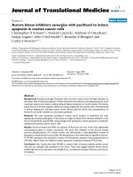
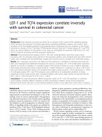
Crank Angle DiagramFigure 1
Crank Angle Diagram. Pre-programmed sensors were
used to stimulate the appropriate muscles during specific
phases of cycle rotation, using a sinusoidal, biphasic wave-
form with a pulse duration of 500 µsec, a phase duration of
1000 µsec and frequency of 50 Hz. Quadriceps and gluteus
stimulation was initiated prior to reaching top dead center
(TDC) during leg extension. Hamstring stimulation was
applied through bottom dead center (BDC), during leg flex-
ion. Stimulation was provided through individual stimulation
channels.
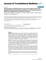
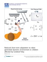
Complete Setup of the FES-LCE SystemFigure 2
Complete Setup of the FES-LCE System. The subject
is seated and secured within the FES-LCE system. The feet
are placed in boots that are fixed to the ergometer pedal.
The thighs are secured with Velcro straps, which help to
maintain movement in the sagittal plane only. Seat depth is
adjusted so that the subject's leg does not fully extend when
the ergometer pedal is 110° with respect to TDC. Reflective
markers were placed at the shoulder, hip, knee, ankle, toe,
heel of boot, pedal spindle, pedal force sensor, ergometer
crank center, and ergometer frame.
Journal of NeuroEngineering and Rehabilitation 2008, 5:14 />Page 4 of 12
(page number not for citation purposes)
cm superior and slightly lateral so that it rested over the
muscle belly of the rectus femoris and vasti. The ham-
string ground electrode was placed a distance of approxi-
mately 6 cm superior to the posterior crease of the knee
joint; situated approximately over the semitendinosus
and short head of the femoral bicep. The active electrode
was placed a distance of 10 cm superior so that the muscle
bellies of the semitendinosus, semimembranosus and
long head of the femoral biceps were covered. The gluteus
maximus ground electrode was placed at the gluteal fold.
The active electrode was placed approximately 4 cm supe-
rior and anterior so as to rest on the muscle belly of the
gluteus maximus. To maintain consistency, electrode
placement was performed by the same person for all sub-
jects.
Kinematic data
Adhesive reflective markers were placed over the humeral
head of the shoulder, approximately 1 cm anterior and
superior to the tip of the greater trochanter, at the center
of the lateral femoral epicondyle, the lateral tip of the
malleolus, and on the lateral side of the ergometer boot at
the approximate location of the fifth metatarsal. Addi-
tional markers were placed at the center of the pedal spin-
dle, on the lateral side of the pedal force sensor, at the heal
of the ergometer boot, and the ergometer crank center, fig-
ure 2. A reference was placed on the frame of the ergom-
eter, vertically aligned with the crank center. The reflective
markers were illuminated using a flood light and contin-
uously video recorded, using the image from a video cam-
era oriented perpendicular to the rider's sagittal plane. A
video-based motion capture software system (Peak
Motus
®
System, Peak Performance Technologies Inc., Den-
ver, CO) was used to measure the displacement of the
crank tip, hip, knee, and ankle joints during cycling (Fig-
ure 4). Displacement data were measured at a frequency
of 60 Hz. The kinematic data were filtered using a 5
th
-
order, zero-lag, low pass Butterworth filter with a cutoff
frequency of 4 Hz. All data were expressed as a function of
crank angle. One complete rotation was the trajectory of
the crank tip as it moved from TDC to bottom dead center
(BDC) and back to TDC (Figure 5). All calculations were
averaged over the last 10 rotations completed at each
resistance level to represent the steady-state values of each
parameter of interest.
Kinetic data
A 4-pin, triax, ICP
®
piezo-electric force transducer (PCB
Piezotronics, Inc., NY) with a full-scale measurement
range (45 to 22 k N compression, 2200 N tension) was
mounted underneath the boot of the right ergometer
pedal to record pedal forces in normal and tangential
directions with respect to the pedal plane. The force data
were collected at a frequency of 180 Hz using a LABView
program (National Instruments Corp
®
, Austin, TX), devel-
oped for the study. A synchronizing signal was transmit-
ted to the kinematic video recording at the onset of pedal
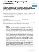
Joint Angle MeasurementsFigure 4
Joint Angle Measurements. Angular displacement of the
hip, knee and ankle were calculated with respect to vertical.
Crank angle was measured with TDC corresponding to 0°.
Pedal angle considered angular changes in the pedal spindle-
boot heal plane with respect to vertical. Values for hip, knee
and ankle power outputs were averaged over the last 10
completed rotations at each resistance level.
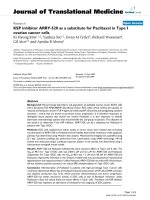
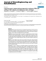
Electrode PlacementFigure 3
Electrode Placement. Approximate locations for elec-
trode placement superficial to QUAD, HAM, and GLUT,
muscles. Active and ground electrodes were spaced approxi-
mately 4 cm apart. The QUAD ground electrode was placed
approximately 5 cm from the patellar apex, HAM ground
electrode was placed approximately 5 cm from the knee
crease, and GLUT ground electrode placed along the gluteal
fold. To maintain consistency, electrode placement was per-
formed by the same person for all subjects.
Journal of NeuroEngineering and Rehabilitation 2008, 5:14 />Page 5 of 12
(page number not for citation purposes)
force acquisition, allowing visual synchronization of the
pedal force and video-recorded kinematic data.
Experimental protocol
A progressive intensity test was conducted in order to
investigate stimulation intensity, joint power outputs,
cadence, resultant pedal force (RPF) and resistance as pos-
sible indicators of fatigue. In the context of this test,
fatigue was defined as the point when the subject could no
longer cycle at or above 10 rpm. The subjects were pas-
sively pedalled through a 2 minute warm-up without
stimulation. Following the warm-up, stimulation inten-
sity was applied so that subjects maintained a constant
cadence of 50 rpm throughout the exercise. 50 rpm was
chosen at the target cadence since this was the cadence at
which the tension of the friction belt was determined in
order to equal 6.25W or 1/8
th
kp. Resistance was then
increased by 1/8
th
kilo-pound (kp) (6.25 W) every two
minutes. A gradient increase of 2 minutes was chosen to
minimize muscular fatigue, but still be considered long
enough to achieve steady-state conditions. Ninety seconds
after each resistance adjustment, force data were recorded
for 30 seconds. Stimulation intensity (mA) and cadence
were also recorded at this time. 140 mA was considered
100% stimulation. The subject's heart rate, blood pressure
and pulse oxygen concentration (SPO2) were also
recorded to ensure that the subject maintained normal
metabolic behaviours. Resistance was increased only to a
level that each subject felt comfortable. If a rider's cadence
dropped below 10 rpm, stimulation was automatically
terminated and the subject was passively cycled through a
2-minute cool-down.
Data analysis
Kinematic data
Reflective marker displacement was calculated using Peak
Motus™ software. The data points were scaled and filtered
as described previously. Corresponding angular velocity
and acceleration were then calculated using Matlab
®
soft-
ware by taking the first and second derivatives of segment
rotations, respectively.
Kinetic data
Free body diagrams of the foot, shank and thigh were con-
structed in order to calculate the forces and torques pro-
duced at the ankle, knee, and hip joints, respectively.
Pedal force, crank angle, segment mass, joint kinematics
and anthropometric data were used to calculate resultant
joint forces and joint moments of force. All equations
were developed with reference to Hull and Jorge's model
for biomechanical analysis of bicycle pedaling [10].
Moments of inertia and centers of gravity were calculated
using Winter's anthropometrical table [28]. Instantaneous
joint power output was calculated using the following
equation:
P = M ×
ω
Where: P = power (W)
M = joint moment of force (N-m)
ω
= joint angular velocity (rad/sec)
Resultant pedal force (RPF), as identified by Brown and
Jensen [11], can be expressed as the vector sum of muscle
forces, gravitational and inertial forces that contribute to
the contact force measured at the pedal. This value was
calculated using the following equation:
Where: RPF = Resultant pedal force (N)
F
Px,y
= Pedal forces in the x- and y-directions, with respect
to the global sagittal plane, respectively (N)
RPF F F
Px Py
=+
22
Geometric Trajectory of the Boot-Pedal SystemFigure 5
Geometric Trajectory of the Boot-Pedal System. Def-
initions of top dead center (TDC), bottom dead center
(BDC), and reference frames for the boot-pedal (ϕ; X
p
, Y
p
)
and ground (Φ; X
c
, Y
c
). θ
p
corresponds to boot-pedal angle
relative to the horizontal and θ
c
corresponds to crank angle
relative to the vertical axis. Leg flexion occurred from 110°–
290°, leg extension occurred from 290°-110° of the crank
angle.
Journal of NeuroEngineering and Rehabilitation 2008, 5:14 />Page 6 of 12
(page number not for citation purposes)
A one-way analysis of variance (ANOVA) was performed
in order to evaluate the difference in mean cadence, mean
stimulation intensity, mean joint power outputs, total
power output and mean resultant pedal force (RPF) with
increasing resistance for the subject group as a whole. A
Tukey test was used as the post-hoc comparison. Statistical
significance was set at p = 0.05. A Pearson product
moment correlation was also performed in order to deter-
mine the strength of the linear relationship between each
of these seven variables. Those variables possessing a
strong or moderate correlation with a joint power output
were entered into a multivariable regression to investigate
the prediction power of these variables on joint power
output. A strong correlation was considered a R coefficient
of at least 0.8. A moderate correlation was considered a
coefficient of at least 0.5. All statistical analyses were car-
ried out using SPSS™ 13.0 software.
Results
The highest level of resistance completed varied between
subjects. Highest completed levels of resistance were: 1/
8
th
kp, 2/8
th
kp (2 subjects), 3/8
th
kp, 4/8
th
kp, and 6/8
th
kp. Data from the five subjects that completed progressive
cycling through 2/8
th
kp were included in the statistical
analyses. Mean and standard deviations were calculated
for cadence, stimulation intensity, ankle power output
(APO), knee power output (KPO), hip power output
(HPO) and resultant pedal force (RPF). (Table 1). Stimu-
lation intensity was expressed as a percentage of maxi-
mum intensity, 140 mA. Mean APO and KPO decreased
with increasing resistance. Mean stimulation intensity,
HPO and RPF were found to increase with increasing
resistance. (Table 1)
Table 1: Group statistics. Mean and standard deviation for cadence, stimulation intensity, ankle power output, knee power output, hip
power output and resultant pedal force (RPF) at each level of resistance.
Resistance (W) Cadence (rpm) Stim Intensity (mA) Ankle PO (mW) Knee PO (mW) Hip PO (mW) RPF (N)
0.0 (n = 5) 48.2 ± 1.90 66.6 ± 20.3 38.8 ± 10.0 120.0 ± 60.0 -88.5 ± 30.0 22.6 ± 5.0
6.25 (n = 5) 48.0 ± 1.70 98.6 ± 26.9 38.1 ± 10.0 98.4 ± 40.0 -20.4 ± 60.0 23.5 ± 4.10
12.5 (n = 5) 41.0 ± 9.70 116.2 ± 28.1 24.5 ± 20.0 26.2 ± 100.0 27.1 ± 30.0 25.03 ± 5.13
Table 2: Pearson Correlation Table for resistance, cadence, stimulation intensity, APO, KPO, HPO and RPF.
Resistance Cadence Stimulation
Intensity
Ankle Power
Output
Knee Power
Output
Hip Power
Output
Resultant Pedal
Force
Resistance Pearson
Correlation
1 .227
Sig. (2-tailed) .417
N15 15
Cadence Pearson
Correlation
476 1 .285
Sig. (2-tailed) .073 .304
N1515 15
Stim Pearson
Correlation
.662(**) 553(*) 1 356
Sig. (2-tailed) .007 .033 .193
N151515 15
APowerOut Pearson
Correlation
346 .864(**) 658(**) 1 .484
Sig. (2-tailed) .207 .000 .008 .067
N151515 15 15
KPowerOut Pearson
Correlation
537(*) .818(**) 837(**) .889(**) 1 .559(*)
Sig. (2-tailed) .039 .000 .000 .000 .030
N151515 15 15 15
HPowerOut Pearson
Correlation
.804(**) 184 .438 108 320 1 .163
Sig. (2-tailed) .000 .512 .102 .701 .245 .562
N151515 15 15 15 15
ResPedalForce Pearson
Correlation
.227 .285 356 .484 .559(*) .163 1
Sig. (2-tailed) .417 .304 .193 .067 .030 .562
N151515 15 15 15 15
** Correlation is significant at the 0.01 level (2-tailed).
* Correlation is significant at the 0.05 level (2-tailed).
Journal of NeuroEngineering and Rehabilitation 2008, 5:14 />Page 7 of 12
(page number not for citation purposes)
The strongest linear correlations existed between: 1) APO
and KPO (r = .89), 2) APO and cadence (r = .86), 3) stim-
ulation intensity and KPO ( 84), 4) cadence and KPO (r
= .82) and 5) resistance and HPO (r = .80). Moderate cor-
relations were observed between 1) stimulation intensity
and resistance (r = .66), 2) stimulation intensity and APO
(r = 66), 3) RPF and KPO (r = .56), 4) cadence and stim-
ulation intensity (r = 55) and 5) resistance and KPO (r =
54) (Table 2).
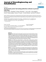
Stimulation intensity & hip power output
Final values of stimulation intensity and HPO were signif-
icantly higher than initial values at 0/8
th
kp (116.2 ± 28.1
mA vs. 66.6 ± 20.3 mA, p = 0.03, and 27.1 ± 30 mW vs. -
88.5 ± 30 W, p < 0.01, respectively). Stimulation intensity
increased 23% between the first two levels of resistance
and an additional 13% by the final resistance level of 2/
8
th
kp. HPO increased 59% from 0/8
th
to 1/8
th
kp, and
increased by 41% at 2/8
th
kp. 100% HPO corresponded to
the maximum power output observed at 2/8
th
kp. (Figure
6)
Cadence
Mean cadence remained close to the target cadence of 50
rpm for the first two resistance levels, experiencing only a
slight decrease of 0.2 rpm (Table 1). Mean cadence
decreased by 7 rpm between 1/8
th
and 2/8
th
kp. Changes
observed in mean cadence were not statistically significant
between any of the resistance levels. (p = 0.12)
Ankle & knee power output
Mean APO and KPO did not change significantly with
increased resistance. Mean APO decreased slightly from 0/
8
th
to 1/8
th
kp, and decreased by 35% by 2/8
th
kp (Figure
7). KPO decreased by 20% between the first two levels of
resistance and decreased another 59% between 1/8
th
and
2/8
th
kp (Figure 8).
Resultant pedal force
RPF did not change significantly with increasing resist-
ance. From 0/8
th
to 1/8
th
kp and 1/8
th
to 2/8
th
kp, RPF
increased by 3.5% and 6.1%, respectively (Figures 9, 10).
Fatigue indices
Regression lines for APO and KPO were developed to cal-
culate indices of fatigue. APO was predicted by cycling
cadence (R
2
= 0.75, p < 0.001). APO = 0.002C - 0.074.
Considering a cadence of 10 rpm as fatigue, ankle fatigue
occurs at -0.054 W. As a result, the index of fatigue repre-
sents the proportion of power present at the ankle joint
with respect to fatigue:
APO
M
APO
F
APO
F
−
= Index of fatigue for Ankle
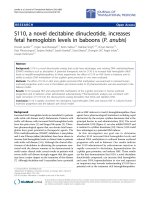
Resistance vs. Hip Power OutputFigure 6
Resistance vs. Hip Power Output. The height of the bars represent the mean hip power output for the subject group at
each resistance level. Negative values represent power absorption, where the direction of force generation opposes the direc-
tion of cycling motion. Positive values indicate power exertion, where the direction of force generation and cycling motion
coincide. The range between the two tails indicates the standard error of the mean. Standard error was set at 95%.
Journal of NeuroEngineering and Rehabilitation 2008, 5:14 />Page 8 of 12
(page number not for citation purposes)
Where APO
M
is ankle power output measured during
cycling. As APO approaches fatigue, the index will
approach 0.
A multiple linear regression of cycling cadence (C), stim-
ulation intensity (S) and RPF (R) provided a significant
predictor of KPO = 0.006C - 0.002S + 0.004R - 0.17 (R
2
=
0.94, p < 0.05). At fatigue, cadence and stimulation inten-
sity were defined as 10 rpm and 100%, respectively. Since
RPF does not have a definitive point of fatigue that can be
measured, the mean value of RPF at 2/8
th
kp was used.
Incorporating this value into the regression equation for
KPO indicates that if fatigue occurs at 2/8
th
kp, KPO will
be -209.88 mW, absorbing power. The index of fatigue
developed for KPO presents the proportion of existing
KPO with respect to fatigue:
KPO
M
KPO
F
KPO
F
−
= Index of fatigue for Knee
Resistance vs. Resultant Pedal ForceFigure 9
Resistance vs. Resultant Pedal Force. RPF quantitatively
represents the contribution of muscle, inertial and gravita-
tional forces that contribute to contact force measured at
the ergometer pedal. [11] The near constant cadence over
the first two resistance levels suggests that the inertial forces
of the thigh, shank and foot were responsible for maintaining
cadence. Additionally, the decrease in hip power absorption
at 1/8
th
kp possibly translated to an increase in RPF. At 2/8
th
kp, the only increase observed was in hip power output.
Inertial forces would have decreased due to the decrease in
ergometer cadence. The subsequent increase in RPF at this
time suggests that the increased muscle forces about the hip
are primarily responsible for this change.
Resistance vs. Ankle Power OutputFigure 7
Resistance vs. Ankle Power Output. The height of the
bars indicate mean ankle power output for the subject group
with increasing resistance. The error bars explain 95% of the
standard deviation from the mean value. Mean APO
remained nearly constant from 0/8
th
to 1/8
th
kp, suggesting
cadence to be the source of APO production. The observed
decrease in ankle power output is likely attributed to the
absence of lower leg stimulation.
Table 3: Calculated Fatigue Index Values. Calculated fatigue
index values for the ankle and knee at each level of resistance.
Resistance Ankle Fatigue Index Values Knee Fatigue Index Values
0/8
th
kp 1.72 1.59
1/8
th
kp 1.71 1.47
2/8
th
kp 1.45 1.12
Resistance vs. Knee Power OutputFigure 8
Resistance vs. Knee Power Output. Mean KPO
decreased with increasing resistance. Since cadence
remained nearly constant between 0/8
th
and 1/8
th
kp, the
decrease in KPO is attributed to a decrease in force genera-
tion in the quadriceps and/or hamstring muscles.
Journal of NeuroEngineering and Rehabilitation 2008, 5:14 />Page 9 of 12
(page number not for citation purposes)
where KPO
M
is measured during cycling and KPO
F
is the
value at fatigue.
Therefore, as KPO approaches fatigue, the index will
approach a value of 0. The fatigue indices were applied to
the group mean APO and KPO values (Table 3). Applica-
tion of the ankle fatigue index indicates that at 0/8
th
kp,
the ankle joint has 1.7 times as much power than levels
calculated for fatigue. Additionally, the ankle power index
decreases to 1.45 by 2/8
th
kp. The knee fatigue index at 0/
8
th
kp was 1.6 times greater than fatigue. The decrease in
knee fatigue index to 1.1 at 2/8
th
kp indicates a greater
reduction in knee power capacity than that experienced at
the ankle. The regression equation for HPO was HPO =
0.009R - 0.085 (p < 0.001), whereby resistance was the
only predictor (R
2
= 0.65). Therefore, no factors define
HPO at fatigue and an index of hip fatigue cannot be
developed.
Discussion
Overview
The main findings of this study were: (1) APO and KPO
decreased with increasing resistance whereas HPO
increased with resistance; (2) cadence, stimulation inten-
sity, and RPF were significant predictors of KPO; and (3)
knowing the value of these predictors at 10 rpm, an index
of fatigue can be developed. This index quantitatively
expresses the power generated at the knee joint with
respect to a baseline power level defined as fatigue.
Ankle
The absence of lower leg stimulation in this exercise sug-
gests that changes observed in APO must be attributed to
changes in ankle angular velocity. Studies have suggested
that plantar-flexion of the ankle joint during late recovery
phase in both able-bodied and SCI subjects was a direct
result of boot-pedal inertial forces [29]. Such inertial
forces would be augmented by changes in cadence [30].
The subsequent changes in mean APO observed in this
exercise demonstrated a strong link to changes in cadence,
supporting the identification of cadence as the only signif-
icant predictor of APO. The inclusion of lower leg stimu-
lation to such muscles as the tibialis anterior, soleus and
gastrocmenius would likely improve cycling performance
and potentially increase the circulatory and cardiovascular
benefits to the user [27,31-34].
Knee
The increase in stimulation intensity and subsequent
decrease in knee power by 1/8th kp, 3.5 minutes into
cycling, are most likely due to premature fatiguing of the
quadriceps and/or hamstrings [12-14]. However, the exact
muscle group that fatigued cannot be identified since all
muscle groups received identical increases in stimulation
when cadence dropped below target. Despite potential
fatigue, 86% of the power generated within the leg was
produced at the knee at 1/8
th
kp. Research involving able-
bodied subjects has reported the quadriceps to remain
active over the largest range of the cycling period [23]. The
Resistance vs. Mean Resultant Pedal ForceFigure 10
Resistance vs. Mean Resultant Pedal Force. The mean RPF values calculated for the subject group as a whole were found
to have a linear relationship with resistance. Mean RPF increased with resistance, r
2
= 0.98.
Journal of NeuroEngineering and Rehabilitation 2008, 5:14 />Page 10 of 12
(page number not for citation purposes)
quadriceps muscles also exhibit the greatest strength in
both paralyzed and able-bodied riders and make a larger
contribution to forward cycling than the hamstrings and
gluteus muscles [18,20,23,27]. Therefore, the quadriceps
may be primarily responsible for knee power output in
this exercise, but additional studies would be required to
confirm this conclusion. Cadence-dependent inertial
forces may have contributed to knee power output as well.
The strong correlation between ankle and knee power out-
puts (r = 0.889, Table 2) may reflect the boot-pedal's con-
tribution to knee joint moment. Also, moments created
by thigh and shank inertial forces may have further
increased knee power output. The decrease in KPO at 2/8
th
kp was likely due not only to a decrease in knee angular
velocity, but also from a decline in inertial force associ-
ated with decreased cadence, subsequently compromising
knee joint moment.
Hip
The hip absorbed power for the first two resistance levels
(Tables 1 and 3). Power absorption is specified by a nega-
tive power value and indicates that the direction of muscle
force production opposes the direction of crank motion.
Power absorption may result from fatigue, improper coor-
dination of flexor and extensor muscle contractions, or
more likely, from opposing inertial forces produced by
the thigh segment that intensify at higher cadence levels
[21,30]. The transition to hip power exertion at 2/8
th
kp
indicates a concurrence in both force and crank directions,
and is most likely due to an increase in muscle forces
resulting from a decrease in ergometer cadence [35]. The
significant increase observed in HPO is consistent with
Ericson's findings involving able-bodied subjects [23,33].
The higher cadences observed at 0/8
th
and 1/8
th
kp, may
have produced thigh inertial forces that were larger in
magnitude and opposite in direction to the force pro-
duced by the gluteus muscles. As a result, the hip joint
absorbed power. At 2/8
th
kp, the decrease in ergometer
cadence resulted in a lower thigh inertial force. While the
inertial force still opposed the direction of muscle force
generation, the magnitude of the gluteus muscle force was
sufficiently larger, promoting power exertion. The transi-
tion from power absorption to exertion at the hip with
decreased cadence supports previous findings that suggest
lower ergometer cadences to be favourable to higher mus-
cle forces [35]. From a mechanical perspective, increased
ergometer resistance incurred an increasingly larger
moment about the hip. To compensate for this increase,
the gluteal muscles increased force production, subse-
quently increasing HPO. Ergometer cadence and moment
arm (pedal to hip) did not change significantly, therefore
their influence on HPO is negligible. Since the hip was the
only joint to exhibit an increase in power output in this
exercise, the gluteal muscles may be the primary source of
both power and continual force generation during FES-
cycling in SCI subjects [21].
Knee fatigue index
The index of fatigue developed in this study assesses a sub-
ject's capacity to pedal as described by their KPO. The
knee was selected for the definition of this index due to its
close proximity to the quadriceps and hamstring muscle
groups. As demonstrated by the knee's regression equa-
tion, different combinations of stimulation and cadence
may be examined to investigate riding conditions that
may augment riding time and increase power output. The
fatigue index value at 0/8
th
kp, measured 90 seconds into
active, unassisted pedaling was 1.6. This indicates initial
power capacity at the knee to be 1.6 times greater than
fatigue. The fatigue index decreased to 1.1 at 2/8
th
kp, rep-
resenting approximately a 30% decrease in the knee's
power capacity within a 4 minute time span. These find-
ings suggest that the present cycling protocol is not suffi-
cient for a rider to gain the benefits of FES and thus raises
speculation as to whether or not progressive resistance
cycling is an appropriate protocol for SCI subjects. The
index values derived from these five subjects, should be
expanded and generalized to a larger population. If simi-
lar results emerge in future studies, this index may be use-
ful within a clinical or experimental setting.
Mixing the results of both complete and incomplete SCI
subjects was not considered a significant influence on the
final outcome of this study. One of the incomplete SCI
subjects produced results comparable to, and in some
cases, better than complete SCI subjects. From this obser-
vation, it was determined that degree and frequency of
ergometer use was a greater influence on the study results
than extent of injury. Furthermore, using a mixed subject
group of complete and incomplete SCI subjects is a truer
representation of the FES-LCE user population. Variation
existed within the subject group due to differences in age,
time since injury (1.5 to 21 years), frequency and extent of
cycling experience, as well as a likely difference in propor-
tion of fast- to slow-twitch muscle fibers present in the
stimulated muscle groups associated with variable atro-
phy. Previously, female SCI subjects have scored signifi-
cantly higher on an endurance index than their male
counterparts whereas no gender differences were noted
between able-bodied control subjects in that particular
study [31]. Other studies have suggested that the proper-
ties of muscle fiber in females may differ from males [36].
Future studies may investigate how the presently devel-
oped indices of fatigue may differ with gender. Addition-
ally, alterations in stimulation timing and intensity could
produce significantly different muscle synergies during
FES cycling. Resulting joint power outputs and the subse-
quent development of a fatigue index would ultimately be
affected. Therefore, the results of this study are valid for
Journal of NeuroEngineering and Rehabilitation 2008, 5:14 />Page 11 of 12
(page number not for citation purposes)
the presently employed stimulation protocol only. Addi-
tional research would be required to verify whether the
present fatigue index is valid under different stimulation
parameters.
Conclusion
This study describes the influence of resistance on joint
power output during FES cycle ergometry and the devel-
opment of a fatigue index. While the objective of FES
cycling ergometry is to help SCI subjects gain improved
circulation, cardiovascular fitness and healthier muscle
and bone, overcoming muscle fatigue is still an obstacle.
Previous studies have found muscle force generation to be
considerably weaker in SCI subjects than in able-bodied
controls. Additionally, a decline in force production
occurred earlier in SCI individuals [13,14]. The rapid
increase in stimulation intensity and subsequent decrease
in cadence and power output observed in this study sug-
gest that the one-size-fits-all stimulation protocol may be
one root cause of premature fatigue. Likewise, the use of a
progressive resistance cycling therapy further contributes
to fatigue onset. An index of fatigue was successfully
developed, comparing knee power capacity during cycling
with a predetermined value of fatigue. However, further
studies should be conducted to determine if the power
output predictors used here are valid for other stimulation
protocols and subject groups.
Competing interests
None of the authors have competing interest or financial
relationship which may affect the results of this study.
Authors' contributions
SAH carried out the ergometer testing, collected force and
kinematic data, performed the statistical analysis and
drafted the manuscript. PDF participated in the design
and coordination of the study, data analysis, and drafting
the manuscript. DJA helped in drafting the manuscript.
Acknowledgements
This study was supported by a grant from the University of Connecticut
Research Foundation.
References
1. Gerrits HL, Hopman MTE, Offringa C, Engelen BG, Sargeant AJ, Jones
DA, Haan A: Variability in fibre properties in paralyzed human
quadriceps muscles and effects of training. Eur J Physio 2003,
445:734-740.
2. Chilibeck PD, Weiss JJC, Bell G, Burnham R: histochemical
changes in muscle of individuals with spinal cord injury fol-
lowing functional electrical stimulated exercise training. Spi-
nal Cord 1999, 37:264-268.
3. Crameri RM, Weston A, Climstein M, Davis GM, Sutton JR: Effects
of electrical stimulation-induced leg training on skeletal
muscle adaptability in spinal cord injury. Scand J Med Sci Sports
2002, 12:316-322.
4. Petrofsky JS, Stacy R, Laymon M: The relationship between exer-
cise work intervals and duration of exercise on lower
extremity training induced by electrical stimulation in
humans with spinal cord injuries. Eur J Appl Physiol 2000,
82:504-509.
5. Hooker SP, Figoni SF, Glaser RM, Rodgers MM, Ezenwa BN, Faghri
PD: physiologic responses to prolonged electrically stimu-
lated leg-cycle exercise in the spinal cord injured. Arch Phys
Med Rehabil 1990, 71(11):863-869.
6. Belanger M, Stein RB, Wheeler GD, Gordon T, Leduc B: Electrical
stimulation: can it increase muscle strength and reverse
osteopenia in spinal cord injured individuals? Arch Phys Med
Rehabil 2000, 81(8):1090-1098.
7. Mohr T, Podenphant J, Biering-Sorensen F, Galbo H, Thamsborg G,
Kjaer M: ncreased bone mineral density after prolonged elec-
trically induced cycle training of paralyzed limbs in spinal
cord injured man. Calcif Tissue Int 1997, 61(1):22-25.
8. Hangartner TN, Rodgers MM, Glaser RM, Barre PS: Tibial bone
density loss in spinal cord injured patients: effects of FES
exercise. J Rehabi Res Dev 1994, 31(1):50-61.
9. Thijssen DH, Ellenkamp R, Smits P, Hopman MT: Rapid vascular
adaptations to training and detraining in persons with spinal
cord injury. Arch Phys Med Rehabil 2006, 87(4):474-481.
10. Hull ML, Jorge M: A method for biomechanical analysis of bicy-
cle pedaling. J Biomechanics 1985, 18(9):631-644.
11. Brown NAT, Jensen JL: The development of contact force con-
struction in the dynamic-contact task of cycling. J Biomechanics
2003, 36:1-8.
12. Mizrahi J, Levy M, Ring H, Isakov E, Liberson A: EMG as an indica-
tor of fatigue in isometrically fes-activated paralyzed mus-
cles. IEEE Trans Rehabil Eng 1994, 2(2):57-65.
13. Tepavac D, Schwirtlich L: Detection and prediction of FES-
induced fatigue. J Electromyogr Kinesiol 1997, 7(1):39-50.
14. Thomas CK: Fatigue in human thenar muscles paralyzed by
spinal cord injury. J Electromyogr Kinesiol 1997, 7(1):15-26.
15. Eser PC, Donaldson NdN, Knecht H, Stüssi E: Influence of differ-
ent stimulation frequencies on power output and fatigue
during FES-cycling in recently injured SCI people. IEEE Trans
Neural Sys Rehabil Eng 2003, 11(3):236-240.
16. Shields RK, Chang Y-J: The effects of fatigue on the torque-fre-
quency curve of the human paralyzed soleus muscle. J Electro-
myogr Kinesiol 1997, 7(1):3-13.
17. Giat Y, Mizrahi J, Levy M: A musculotendon model of the fatigue
profiles of paralyzed quadriceps muscle under FES. IEEE Trans
Biomed Eng 1993, 40(7):664-674.
18. Trumbower RD, Rajasekaran S, Faghri PD: Identifying offline mus-
cle strength profiles sufficient for short-duration FES-LCE
exercise: a PAC learning model approach. J Clin Monit Comput
2006, 20(3):209-220.
19. Gföhler M, Lugner P: Cycling by means of functional electrical
stimulation. IEEE Trans Rehabil Eng 2000, 8(2):233-243.
20. Bratt A, Ericson MO: Biomechanical model for calculations of
joint loads during ergometer cycling. Technical Reports from the
Royal Institute of Technology 1985.
21. Franco JC, Perell KL, Gregor RJ, Scremin AME: Knee kinetics dur-
ing functional electrical stimulation induced cycling in sub-
jects with spinal cord injury: a preliminary study. J Rehabil Res
Devel 1999, 36(3):207-216.
22. Ericson M: On the biomechanics of cycling. A study of joint
and muscle load during exercise on the bicycle ergometer.
Scand J Rehabil Med Suppl 1986, 16:1-43.
23. Ericson M: Mechanical muscular power output and work dur-
ing ergometer cycling at different work loads and speeds. Eur
J Appl Physiol 1988, 57:382-387.
24. Neptune RR, Herzog W: The association between negative
muscle work and pedaling rate. J Biomech 1999, 32:1021-1026.
25. Ericson MO, Ekholm J, Svensson O, Nisell R: The forces of ankle
joint structures during ergometer cycling. Foot Ankle 1985,
6(3):135-142.
26. Ferguson RA, Aagaard P, Ball D, Sargeant AJ, Bangsbo J: Total power
output generated during dynamic knee extensor exercise at
different contraction frequencies. J Appl Physiol 2000,
89:1912-1918.
27. Trumbower RD, Faghri PD: Improving pedal power during sem-
ireclined leg cycling. IEEE Eng Med Biol 2004, 23(2):62-71.
28. Enderle JD, Blanchard S, Bronzino J: Introduction to Biomedical Engineer-
ing San Diego: Academic Press; 2000.
Publish with BioMed Central and every
scientist can read your work free of charge
"BioMed Central will be the most significant development for
disseminating the results of biomedical research in our lifetime."
Sir Paul Nurse, Cancer Research UK
Your research papers will be:
available free of charge to the entire biomedical community
peer reviewed and published immediately upon acceptance
cited in PubMed and archived on PubMed Central
yours — you keep the copyright
Submit your manuscript here:
/>BioMedcentral
Journal of NeuroEngineering and Rehabilitation 2008, 5:14 />Page 12 of 12
(page number not for citation purposes)
29. Trumbower RD, Faghri PD: Kinematic Analysis of semireclined
leg cycling in able-bodied and spinal cord injured individuals.
Spinal Cord 2005, 43:543-549.
30. Serway RA: Physics For Scientists and Engineers Fourth edition. United
States of America: Saunders College Publishing; 1996.
31. Stein RB, Gordon T, Jefferson J, Sharfenberger A, Yang JF, Totosy De
Zepetnek J, Belanger M: Optimal stimulation of paralyzed mus-
cle after human spinal cord injury. J Appl Physiol 1992,
72(4):1393-1400.
32. Faghri PD, Yount JP, Pesce WJ, Seetharama S, Votto JJ: Circulatory
hypokinesis and functional electric stimulation during stand-
ing in persons with spinal cord injury. Arch Phys Med Rehabil
2001, 82:1587-1595.
33. Ericson MO, Nisell R, Arborelius UP, Ekholm J: Muscular activity
during ergometer cycling. Scand J Rehabil Med 1985, 17(2):53-61.
34. Li L, Caldwell GE: Muscle coordination in cycling: effect of sur-
face incline and posture. J Applied Physiol 1998, 85(3):927-934.
35. Forusek C, Davis GM: Maximizing muscle force via low-
cadence functional electrical stimulation cycling. J Rehabil Med
2004, 36:232-237.
36. Simoneau JA, Bouchard C: Human variation in skeletal muscle
fiber-type proportion and enzyme activities. Am J Physiol 1989,
257:E567-E572.