Báo cáo hóa học: "Signal Processing with Teams of Embedded Workhorse Processors" pdf
Bạn đang xem bản rút gọn của tài liệu. Xem và tải ngay bản đầy đủ của tài liệu tại đây (1.43 MB, 16 trang )
Hindawi Publishing Corporation
EURASIP Journal on Embedded Systems
Volume 2006, Article ID 69484, Pages 1–16
DOI 10.1155/ES/2006/69484
Signal Processing with Teams of Embedded
Workhorse Processors
R. F. Hobson, A. R. Dyck, K. L. Cheung, and B. Ressl
School of Engineering Science, Simon Fraser University, Burnaby, BC, Canada V5A 1S6
Received 4 December 2005; Revised 17 May 2006; Accepted 17 June 2006
Recommended for Publication by Zoran Salcic
Advanced signal processing for voice and data in w ired or wireless environments can require massive computational power. Due
to the complexity and continuing evolution of such systems, it is desirable to maintain as much software controllability in the field
as possible. Time to market can also be improved by reducing the amount of hardware design. This paper descr ibes an architecture
based on clusters of embedded “workhorse” processors which can be dynamically harnessed in real time to support a wide range
of computational tasks. Low-power processors and memory are important ingredients in such a highly parallel environment.
Copyright © 2006 R. F. Hobson et al. This is an open access article distributed under the Creative Commons Attribution License,
which permits unrestricted use, distribution, and reproduction in any medium, provided the original work is properly cited.
1. INTRODUCTION
Low cost networks have created new opportunities for voice
over internet applications (VoIP). High channel count voice
signal processing potentially requires a wide variety of com-
putationally demanding real-time software tasks. Also, the
third generation of cellular networks, known as 3G cellular,
is deployed or being installed in many areas of the world.
The specifications for wideband code division multiple ac-
cess (WCDMA) are written by the third generation partner-
ship project (3GPP) to provide a variety of features and ser-
vices beyond second generation (2G) cellular systems. Simi-
larly, time division synchronous code division multiple ac-
cess (TD-SCDMA) specifications have emerged for high-
density segments of the wireless market. All of these enabling
carrier techniques require sophisticated voice and data signal
processing algorithms, as older voice carrying systems have
[1–5].
Multichannel communication systems are excellent can-
didates for parallel computing. This is because there are
many simultaneous users who require significant computing
power for channel signal processing. Different communica-
tion scenarios lead to different parallel computing require-
ments. To avoid over-designing a product, or creating silicon
that is unnecessarily large or wasteful of power, a design team
needs to know what the various processing requirements are
for a particular application or set of applications. For ex-
ample, legacy voice systems require 8-bit sampled inputs at
8 kHz per channel, while a 3G wireless base-station could
have to process complex extended data samples (16-bit real,
16-bit imaginar y ) at 3.84 MHz from several antenna sources
per channel, a whopping 3 orders of magnitude different in-
put bandwidth per channel. Similarly, interprocessor com-
munication bandwidth is very low for legacy voice systems,
but medium-high for WCDMA and T D-SCDMA where in-
termediate computational results need to be exchanged be-
tween processors.
The motivation for this work came from two previ-
ous projects. The first was a feasibility study where tiny
(low silicon area) parallel embedded processors were used
for multichannel high-speed ATM reassembly [6]. At about
the same time, it was observed that the telecom indus-
try was manufactur ing boards with up to 2-dozen discrete
DSP chips on them, and several such boards would be re-
quired for a carr ier-class voice system. Another feasibil-
ity study showed that parallel embedded-processing tech-
niques could be applied to reduce the size and power re-
quirements of these systems [7]. To take advantage of this,
Cogent ChipWare, Inc. was spun off from Simon Fraser
University in 1999. Cogent had a customer agreement to
build its first generation VoIP chip, code named Fraser,
but due to fallout associated with the recent high-tech
“crash” this did not reach fruition. Some additional work was
done at Cogent related to WCDMA and TD-SCDMA base-
station algorithms for a possible second generation prod-
uct.
2 EURASIP Journal on Embedded Systems
Table 1: A summary of SoC features for VoIP and base-station chips.
Chip GMACS
Memory # Size +/
− Speed Power PCM Ch.
MB Proc. 10% mm
2
MHz W 128 ms ECAN
Calisto 2.71.84 21 117 166 1.2 184
TNETV3010
3.63.0 6 190 300 1(+I/O) 192
Entropia III
28 ? 10 ? ? 3 1008
PC102
38.41.0 322 210 160 5 ?
FastMath
32 1.03 17 ? 2000 13.5?
Fraser (simulation)
12.22.3 40 115 320 1.3 1024
This pap er addresses signal processing bandwidth re-
quirements, parallel computing requirements, and system
level performance prediction for advanced signal process-
ing applications drawn from the voice telephony and wire-
less base-station areas. The proposed solutions can support
high channel counts on a sing le chip with considerable flex-
ibility and low-power per channel. A new hierarchical pro-
cessor clustering technique is presented and it is shown that
memory deployment is critical to the efficiency of a parallel
embedded processor system. A new 2-dimensional correla-
tion technique is also presented to help show that algorith-
mic techniques are also critical in resource limited embedded
systems-on-chip.
1.1. Related work
There were several commercial efforts to design and imple-
ment parallel embedded processor architectures for voice ap-
plications, all going on at about the same time in compa-
nies such as BOP’s, Broadcom, Centillium, Chamelion, In-
trinsity, Malleable, Motorola, PACT, Picochip, Texas Instru-
ments, and VxTel [8, 9]. In this section we summarize a
cross-section of these approaches. Table 1 shows some of the
critical differentiating features of the chips which are pre-
sented in the following sections.
Both Calisto and TNETV3010 use on-chip memory for
all channel data, so their channel counts are low at 128 mil-
liseconds of echo cancellation (ECAN) history. Entropia III
and Fraser (this work) have off chip memories for long echo
tails. Off-chip bandwidth for echo data is very low, hence I/O
power for this is a fraction of total power (this is discussed
further below).
PC102 and FastMath are marketed for wireless infras-
tructure (e.g., base-stations). Comparisons between Fraser
(and derivatives) and these processors are made in Sections 7
and 8.
1.1.1. Calisto
With the acquisition of Silicon Spice and HotHaus Tech-
nologies, Broadcom had the ingredients for the successful
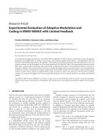
Calisto VoIP chip [10]. Calisto is based on 4 clusters of 4
SpiceEngine DSP’s, as shown in Figure 1. The 130 nm CMOS
chip runs at 166 MHz and dissipates up to 1.2 W. The array
is a hierarchy with a main processor at the top, 4 cluster pro-
JTAG Boot Packet I/O TDM I/O
CM (256 KB) CM (256 KB)
SE SE MB SE SE MB
SE SE CP SE SE CP
SM (768 KB) Hub MP SDRAM I/O
CM (256 KB) CM (256 KB)
SE SE MB SE SE MB
SE SE CP SE SE C
SE: SpiceEngine DSP
MB: memory bridge
MP:mainprocessor
CP: cluster processor
CM: cluster memory
SM: shared memory
Figure 1: Calisto BCM1510 block diagram.
cessors in the middle, and 16 SpiceEngine’s at the bottom.
The SpiceEngines are vector processors with 1 KB instruction
cache and 1 KB vector register file. Cluster processor cache
lines, a wide 196 B, are fi lled over a 128 bit bus from shared
memory. Total chip memory is about 1.8MB.
Vector processor concepts work very well for multichan-
nel data streams with variable length frame size. This is dis-
cussed further in [11]. Our own work presented below also
makes extensive use of vectors.
Memory sharing for both programs and data helps to
conserve area and power. One might be concerned about
memory thrashing with many DSP’s and cluster processors
contending for shared memory. The miss cost is reported to
be 0.1-0.2 cycles per instruction (80–90% hit rate) [10].
R. F. Hobson et al. 3
SARAM
DARAM
TMS320C55x
CACHE
Peripherals
6 DSP units
SARAM
DARAM
TMS320C55x
CACHE
Peripherals
Shared memory
Global
DAM
UTOPIA PCI eMcBSP HDLC
Figure 2: TNETV3010 block diagram.
A telecom “blade” capable of supporting up to 1008
“light-weight” (mostly G.711 + Echo cancellation, ECAN)
voice channels requires an array of 5 Calisto chips. This only
supports 32 milliseconds of ECAN. For 128 milliseconds of
ECAN, the chip count would need to be 6. This product
is geared more towards supporting a very wide selection of
channel services than a high channel count.
1.1.2. TNETV3010
Texas Instruments has a wide variety of DSP architectures to
choose from. To compete in the high density voice arena, they
designed the TNETV3010 chip, which is based on 300 MHz
DSP’s of similar architecture to the C55 series DSP’s, as
shown in Figure 2 [12]. Six DSP units with local memory,
and access to shared memory, are tied to various peripherals
through global DMA. TNETV3010 has the largest amount
of on-chip memory of the examples in Table 1, 3 MB, split
between the DSP units and the shared memory.
The maximum light-weight voice channel count for this
chip is 336, but this does not appear to include ECAN. With
128 milliseconds of ECAN the channel count drops to 192.
Thus 6 chips are required for 1008 channels with 128 mil-
liseconds of ECAN. Like Calisto, TNETV3010 is marketed
with a very broad set of channel options.
1.1.3. FastMATH
The intrinsity FastMATH processor has a 32-bit MIPS core
with 16 KB instruction and data caches plus a 4
× 4mesh
connected array of 32-bit processing elements (PE) [13, 14].
A 1 MB level 2 cache is also on chip with additional mem-
ory accessible through a double data rate (DDR) SDRAM
controller. I/O is provided via 2 bidirectional RapidIO ports.
The PE array appears to the MIPS core as a coprocessor. It
executes matrix type instructions in an SIMD fashion. This
architecture stands out for its 2 GHz clock rate, 512 bit wide
bus from the L2 cache to the PE array, and 13.5W power
consumption. It is not marketed in the same VoIP space
as Calisto or TNETV3010, but is offered for wireless base-
station infrastructure.
1.1.4. Entropia III
Centillium’s fourth generation VoIP has a 6 element DSP
“farm” for channel algorithms and a 4 element RISC pro-
cessor “farm” for network functions, as shown in Figure 3
[15, 16]. Available information does not describe how they
achieve 28 GMACs. A dual SDRAM interface is used for both
echo history data as well as program code. At the reported
power level, this interface would be used mainly for ECAN
data with programs executing out of cache.
1.1.5. PicoArray
PicoChip has one of the most fine-grain embedded processor
arrays commercially available. A small version of it is shown
in Figure 4 [17, 18]. The second generation PC102 picoArray
has 329 16-bit processors divided into 260 “standard” (STD),
65 “memory” (MEM), and 4 “control” (CTL) processors. In
addition, there are 15 coprocessors “function-accelerators”
(FA) that have special hardware to assist with some targeted
algorithms. The main application area is wireless infrastruc-
ture (e.g., base-stations).
Interprocessor communication is provided by a switch-
ing array that is programmed to transfer 32-bit words from
one point to another in a 160 MHz cycle time. Each small cir-
cle represents a transfer mechanism as shown in the bottom
left of the figure. The larger “switching” circles have 4 inputs
and 4 outputs. The switches are pre-programmed in a state-
machine manner to pass data on each cycle from inputs to
outputs. Tasks that do not require data at the full clock rate
can share switch ports with other tasks that do not require
data at the full clock rate.
PC102 has relatively little on-chip memory for applica-
tion code and data on a per-processor basis. It requires algo-
rithm code to be broken up into small units, so large algo-
rithms require many processors to operate in a tightly cou-
pled fashion. Changing algorithms on-the-fly could require
reprogramming the entire switching matrix.
1.1.6. Fraser
Many of the details of Cogent’s Fraser architecture are dis-
cussed in the remainder of this paper. Figure 5 shows a hier-
archy of processors arranged in 3 groups. The building block
is called a pipelined embedded processor (PEP). It consists
of 2K
× 32 program memory, 12K × 32 data memory, and a
core with RISC-like data path and a DSP unit [19–22]. The
central group contains 4 “clusters” of 8 PEP’s, which are con-
sidered “leaf-level” processors. Each end (left, right) has a 4-
processor group that is considered to be at the “root” level.
Oneprocessorateachendmaybereservedasasparefor
yield enhancement. The other processors are assigned to spe-
cific functions or algorithms, such as storing and retrieving
echo data history (off-chip); program code loading (from
on- o r off-chip); data input management; and data output
management. All of the processors are joined together via a
scan chain that is JTAG based.
4 EURASIP Journal on Embedded Systems
TDM interfaces
Sigma DSP
+ ADPCM
Sigma DSP
+ ADPCM
Sigma DSP
+ ADPCM
Sigma DSP
+ ADPCM
Sigma DSP
+ ADPCM
Sigma DSP
+ ADPCM
Dual SDRAM
interfaces
Queue
Buffer
Host interfaceHost interface
MIPS32
4K
MIPS32
4K
MIPS32
4K
MIPS32
4K
Hardware
accelerator
Network interfaces
Figure 3: Entropia III block diagram.
Host processor interface
SS S
P PPPP PPPP P
S
S
S
P PPPP PPPP P
S
S
S
P PPPP PPPP P
SS S
P PPPP PPPP P
SS S
External memory interface
MUX
Figure 4: PicoArray block diagram.
Fraser did not require high processor-to-processor band-
width, so each cluster has a shared memory at either end for
root-level communication. Also, the root processors have a
root-level shared memory. The buses are time-slotted so each
processor is guaranteed a minimum amount of bus time. If
a processor does not need the bus, it can remove itself from
the time slot sequence. Motivation for the architecture and
additional details are presented in the follow ing sections.
2. PARALLEL COMPUTING MODELS
When there are several data sets to be manipulated at the
same time, one is likely to consider the single-instruction
multiple-data (SIMD) par a llel computer model [23]. This
model assumes that most of the time the same computer in-
struction can be applied to many different sets of data in par-
allel. If this assumption holds, SIMD represents a very eco-
nomical parallel computing para digm.
Multiuser communication systems, where a single algo-
rithm is applied to many channels (data sets), should qual-
ify for SIMD status. However some of the more complicated
algorithms, such as low-bit rate voice encoders,
1
have many
data dependent control structures that would require multi-
ple instruction streams for various periods of time. Thus, a
pure SIMD scheme is not ideal. Adding to this complication
is the requirement that one may have to support multiple al-
gorithms simultaneously, each of which operates on different
amounts of data. Furthermore, multiple algorithms may be
applied to the same data set. For example, in a digital voice
coding system, a collection of algorithms such as echo cancel-
lation, voice activity detection, silence suppression, and voice
compression might be applied to each channel.
This situation is similar to what one encounters in a mul-
titasking operating system, such as Unix. Here, there is a task
mix and the operating system schedules these tasks according
to some rules that involve, for example, resource use and pri-
ority. The Ivy Cluster concept was invented to combine some
of the best features of SIMD and multitasking, as well as to
take into account the need for modularity in SOC products
[24]. The basic building-block is a “Workhorse” processor
(WHP) that can be harnessed into variable sized teams ac-
cording to signal processing demand. To capture the essence
of SIMD, a small WHP program memory is desirable, to save
both silicon area and power by avoiding unnecessary pro-
gram replication. A method to load algorithm code “(code
swapping)” into these memories is needed. For this scheme
to work, the algorithms used in the system must satisfy two
properties.
(1) The algorithm execution passes predictably straight
through the code on a per-channel basis. That is, the
algorithm’s performance characteristics are bounded
and deterministic.
(2) The algorithm can be broken down in a uniform way
into small pieces that are only executed once per data
set.
Property 2 means that you should not break an algorithm in
the middle of a loop (this condition can be relaxed under
some circumstances). Research at Simon Fraser University
(SFU), and subsequently at Cogent ChipWare, Inc. has
1
Examples include AMR, a 3G voice coding standard, and ITU standards
G.723.1 and G.729, used in voice-over-packet applications.
R. F. Hobson et al. 5
I/O
Host PCI
Data Data
8 cluster processors
Data Data
Pgm.
Core
Pgm.
Core
Code bus
Pgm.
Core
Pgm.
Core
Core
Pgm.
Core
Pgm.
Cluster bus
Core
Pgm.
Core
Pgm.
I/O
Data Data
Root bridge
Data Data
I/O
Data Data Data Data
Pgm.
Core
Pgm.
Core
Pgm.
Core
Pgm.
Core
Core
Pgm.
Core
Pgm.
Core
Pgm.
Core
Pgm.
Data Data Data Data
I/O
Shared memory; root bus; miscellaneous
Shared memory; root bus; miscellaneous
H.110
E-SRAM
Figure 5: Fraser block diagram.
verified that voice coding, 3G chip rate processing, error-
correcting-code symbol processing, and other relevant com-
munications algorithms s atisfy both properties. What differs
between the algorithms is the minimum “code page” size that
is practical. This code page size becomes a design parame-
ter. It is not surprising that we can employ this code distri-
bution scheme because most modern computers work with
the concepts of program and data caches, which exploit the
properties of temporal and spatial locality. Marching straight
through a code segment demonstrates spatial locality, while
having loops embedded within a short piece of code demon-
strates temporal locality. Cogent’s Ivy Cluster concept differs
significantly from the general concept of a cache because it
takes advantage of knowing which piece of code is needed
next for a particular algorithm (task). General purpose com-
puters must treat this as a random event or try to predict
based on various assumptions. Deterministic program exe-
cution rather than random behavior helps considerably in
real-time signal processing applications.
SIMD architectures are considered “fine grain” by com-
puter architects because they have minimal resources but
replicate these resources a potentially large number of times.
As mentioned above, this technique can be the most effective
way to harness the power of parallelism. Thus it is desirable
to have a WHP that is efficient for a variety of algorithms, but
remains as “fine grain” as possible.
Multiple-instruction multiple-data (MIMD) is a general
parallel computing paradigm, where a more arbitrary col-
lection of software is run on multiple computing elements.
By having multiple variable-size teams of WHP’s, processing
power can be efficiently al located to solve demanding signal
processing problems.
The architectures cited in Section 1.1 each have their
unique way of parallel processing.
2.1. Voice coding
Traditional voice coding has low I/Obandwidth and very low
processor-to-processor communication requirements, wh en
compared with WCDMA and TD-SCDMA. Voice compres-
sion software algorithms such as AMR, G729, and G723.1
can be computationally and algorithmically complex, involv-
ing (relatively) large volumes of program code, so the mul-
titasking requirements of voice coding may be significant. A
SOC device to support a thousand voice channels is challeng-
ing when echo cancellation with up to 128 millisecond echo
tails is required. Data memory requirements become signifi-
cant at high channel counts.
In addition to providing a tailored multitasking environ-
ment, specialized arithmetic support for voice coding can
make a large difference to algorithm performance. For exam-
ple, fractional data (Q-format) support, least-mean-square
loop support, and compressed-to-linear (mu-law or a-law)
conversion support all improv e the overall solution perfor-
mance at minimal hardware expense.
2.2. WCDMA
Cluster technology is well suited to baseband receive and
transmit processing portions of the WCDMA system. Specif-
ically, we can compare the requirements of chip rate pro-
cessing and s ymbol rate convolutional encoding or decoding
with voice coding. Two significant differences are the follow-
ing.
(1) WCDMA requires a much higher I/O bandw idth than
voice coding. Multiple antenna inputs need to be con-
sidered.
(2) WCDMA has special “chip” level Boolean operations
that are not required in voice coding computation.
This will affect DSP unit choices.
The I/O bandwidth is determined by several factors includ-
ing the number of antennas, the number of users, data pre-
cision, and the radio frame distribution technique. Using a
processor to relay data is not as effective as having data de-
livered directly (e.g., broadcast) for local processing. Simi-
larly, using “normal” DSP arithmetic features for chip level
6 EURASIP Journal on Embedded Systems
processing is not as effective as providing specific support for
chip level processing.
The difficulty here is to choose just the right amount
of “application-specific” support for a WHP device. A good
compromise is to have a few well-chosen DSP “enhance-
ments” that support a family of algorithms so a predom-
inantly “software-defined” silicon system is possible. This
is an area where “programmable” hardware reconfiguration
can be effectively used.
WCDMA’s data requirements do not arise entirely from
the sheer number of users in a system as in a gateway
voice coding system. Some data requirements derive from
the distribution of information through a whole radio frame
(e.g., the transport format combination indicator bits, TFCI)
thereby forcing some computations to be delayed. Also, some
computations require averaging over time, implying fur-
ther data retention (e.g., channel estimation). On-chip data
buffers are required as frame information is broadcast to
many embedded processors. A WCDMA SOC solution will
have high on-chip data memory requirements even with an
external memory.
Inter-processor communication is required in WCDMA
for activities such as maximum ratio combining, closed-loop
power control, configuration control, chip-to-symbol level
processing, random access searching, general searching, and
tracking.
In some respects, WCDMA is an even stronger candidate
for SIMD parallelism than voice coding. This is b ecause rel-
atively simple activities, such as chip level processing asso-
ciated with various t ypes of search, can occupy a relatively
high percentage of DSP instruction cycles. Like voice coding,
WCDMA requires a variety of software routines that vary in
size from tiny matched filter routines up to larger Viterbi and
turbo processing routines, and possibly control procedures.
2.3. TD-SCDMA
TD-SCDMA requires baseband receive chip-rate processing,
with a joint detection multiuser interference cancellation
scheme. Like WCDMA, a higher I/O bandwidth than voice
coding is required. Two significant features are the following.
(1) TD-SCDMA with joint detection requires much more
sophisticated algebraic processing of complex quanti-
ties.
(2) Significant processor-processor communication is nec-
essary.
Since TD-SCDMA includes joint detection, it has special
complex arithmetic requirements that are not necessary for
either voice coding or WCDMA. This may take the form of
creating a large sparse system matrix, followed by Cholesky
factorization with forward and backward substitution to
extract encoded data symbols. Unlike voice coding and
WCDMA, such algorithms cannot easily fit on a single fine-
grained WHP and must instead be handled by a team of sev-
eral WHP’s to meet latency requirements. Consequently, this
type of computing requires much more processor-processor
communication to pass intermediate and final results be-
tween processors. Another cause of increased interproces-
sor communication arises from intersymbol interference and
the use of multiple antennas. Processors can be at times
dedicated to a particular antenna, but intermediate results
must be exchanged between the processors. Broadcasting
data from one processor to the other processors in a cluster
(or a team) is an important feature for TD-SCDMA.
Multiplication and division of complex fractional (Q-
format) data to solve simultaneous equations is more dom-
inant in TD-SCDMA than in voice coding (although some
voice algorithms use Q-format) and WCDMA. WCDMA is
also heavy on complex ar ithmetic but it is more amenable to
hardware assists than in TD-SCDMA.
The most time-consuming software routines needed for
TD-SCDMA (i.e., joint detection) do not occupy a large pro-
gram memory space. However, there is still a requirement for
a mix of software support.
2.4. Juggling mixed requirements
Each application has features in common as well as special re-
quirements that will be difficult to support efficiently without
some custom hardware. One common feature is the need for
sequences of data, or vectors. This is quite applicable to voice
coding, for example, because a collection of voice samples
over time forms a vector data set. These data sets can be as
short as a few samples or as long as 1024 samples depending
on circumstances. Similarly, WCDMA data symbols spread
over several memory locations can be processed as vectors.
The minimum support for vector data processing can be cap-
tured by three features:
(1) a “streaming” memory interface so vector data samples
(of varying precision) are fetched every clock cycle;
(2) a processing element that can receive data from mem-
ory every clock cycle (e.g., a DSP unit);
(3) a looping method so programmers can w rite efficient
code.
The concept of data streaming works for all of the applica-
tions being discussed, where the elements involved can be
local memories, shared global memories, first-in first-out
(FIFO) memories, or buses. Since not all of these features are
needed by all of the algorithms, tradeoffsmustbemade.
Another place where difficultchoicesmustbemadeis
in the ty pe of arithmetic support provided. TD-SCDMA’s
complex arithmetic clearly benefits from 2 multipliers, while
some of the other algorithms benefit from only 1 multiplier.
Other algorithms do not need any multipliers. As will be
shown in Section 9, DSP area is not a significant percentage
of the whole. Bus-width to local data memory is a more im-
portant concern, as power can increase with multiple mem-
ory blocks operating concurrently. The potential return from
a DSP unit that has carefully chosen run-time reconfigura-
bility can outweigh the silicon area taken up by the selectable
features. To first order, as long as the WHP core area does
not increase at a faster rate than an algorithm’s MIPS count
decreases, adding hardware can be beneficial. This assumes
that a fixed total number of channels must be processed,
R. F. Hobson et al. 7
Table 2: Alternative bus configurations.
32-bit cluster bus Round Robin Round Robin Round Robin enhanced + Input Cluster to cluster
(320 MHz) standard enhanced local broadcast broadcast bus FIFO
Configurations: I II III IV V
Latency
2M write 1M write 1M write
Data dependent Few cycles
2M read 1M read —
Bandwidth ∼ 80 Mbps
per processor
∼ 160 Mbps
per processor
∼ 160 Mbps write 1.28 Gbps 1.28 Gbps
M
= 8
and so more channels per processor means fewer processors
overall. Another constraint is that there must be enough lo-
cal memory to support the number of channels according
to MIPS count. Too much local memory may slow the clock
rate, thereby reducing the channel count per processor.
For example, if 48 KB is the local memory l imit and
40 KB are available for channel processing where a chan-
nel requires 1.6 KB of data, then the maximum number of
channels would be 25 per WHP. If initially a particular algo-
rithm requires 20 MIPS, only 16 channels can be supported
(at 320 MHz) due to l imited performance. If DSP (or soft-
ware) improvements are made, there is no point in reducing
the MIPS requirement for a channel below 14, as that would
support 25 channels. Frequency can also be raised to increase
channel counts. However, there are frequency limits imposed
by memory blocks, the WHP pipeline structure, and global
communication.
3. IVY CLUSTERS
In order to support multiple concurrent signal processing ac-
tivities, an array of N processors must be organized for effi-
cient computation. For minimal processor-processor inter-
ference all N processors should be independent. However,
this is not possible for a variety of reasons. First, the proces-
sors need to be broken into groups so that instruction dis-
tribution buses and data buses have a balanced load. Also, it
is more efficientifeachprocessorhasalocalmemory(ded-
icated, with no contention) and appropriate global commu-
nication structures. When software is running in parallel on
several processors, interprocessor communication necessar-
ily takes a s mall portion of execution time. By using efficient
deterministic communication models, accurate system per-
formance predictions are possible.
A shared global memory can serve several purposes.
(i) Voice (or other) data can be accessed from global
memory by both a telecom network I/O processor and
apacketdatanetworkI/O processor.
(ii) Shared data tables of constant data related to a lgo-
rithms such as G729 can be stored in the shared mem-
ory, thereby avoiding memory replication. This frees
memory (and consequently area) for more data chan-
nels.
(iii) Dynamic random access memory (DRAM) can be
used for global memories, if desired, to save chip area,
because the global memory interface can deal with
DRAM latency issues. Processor local memories must
remain static random access memory (SRAM) to avoid
latency. However, DRAM blocks tend to have a fairly
large minimum size, which could be much more than
necessary.
(iv) Global memory can be used more effectively when
spread over several processors, especially if the proces-
sors are executing different algorithms.
For high bandwidth I/O or interprocessor communication,
a shared global memory a lone may not be adequate. Table 2
shows five configuration alternatives that could be cho-
sen according to algorithm bandwidth requirements. Stan-
dard round-robin divides the available bus bandwidth evenly
amongst M processors. Split transactions (separate address
and data) set the latency to 2M bus cycles. Enhanced round-
robin permits requests to be chained (e.g., for vector data),
cutting the latency to M bus cycles (2M for the first element
of a vector). With local broadcast, data can be written by one
processor to e ach other processor in a cluster. Input broad-
cast is used, for example, to multiplex data from several an-
tennas and distribute it to clusters over a dedicated bus. Clus-
ter to cluster data exchanges permit adjacent clusters to pass
data as part of a distributed processing algorithm. All of these
bus configurations can be used effectively for various aspects
of the communication scenarios mentioned above. The bus
data width (e.g., 32 or 64 bits) is yet another bandwidth se-
lection var iable.
The name Ivy Cluster (or just Cluster) refers to a group
of processors that have a common code distribution bus (like
the stem of a creeping Ivy plant), a l ocal memory, and global
communication structures that have appropriate bandwidth
for the chosen algorithms. Figure 6 can serve as a reference
for Table 2 configurations. Code distribution is described in
the next section. The proper number of leaf level processors
(L) in a cluster depends on a variety of factors, for exam-
ple, on how much contention can be tolerated for a shared
(single-port) global memory with M
= L + K round-robin
accesses, where K is the number of root level processors. One
must also pay attention to the length of the instruction dis-
tribution bus, and memory data and address buses. These
buses should be short enough to support single clock cycle
8 EURASIP Journal on Embedded Systems
Cluster module
Data distribution bus (optional)
Code distribution bus
Replicatable WHP
Program
memory
Processor
core
DSP
unit 2
(optional)
Bus
interface
DSP
unit 1
Local data
memory
More cluster
processors
Shared cluster data bus
Shared
memory
Shared
memory
Off-chip
memory
req.
(optional)
Task cont rol
processors
(TCP)
Data
interface
(optional)
Off-chip
memory
control
Shared root data bus
Host
processor
I/O
processor(s)
Other
root level
processors
Figure 6: Basic shared bus cluster configuration.
Task boundaries
-10ms 10ms 20ms 30ms 40ms 50ms 60ms
Subtask boundaries
Figure 7: Code page swapping for multiple tasks.
data transfer. Buffering, pipelining, and limited voltage swing
techniques can be used to insure that this is possible.
Note that bus arbitration is a significant issue in itself.
The schemes discussed in this paper assume that all of the
processors have deterministic and uniform access to a bus.
4. TASK CONTROL
Figure 6 shows a typical Cluster configuration where there
may be several processors (e.g., 8 in Fraser) in a Cluster mod-
ule. To conserve silicon area, each Cluster processor has a
modest amount of program memory, nominally 2K words.
A task control processor (TCP) is in charge of code distri-
bution, that is, downloading “code pages” into various pro-
gram memories [19, 25]. Several Cluster modules may be
connected to a single TCP. For larger service mixes, 2 TCPs
may be used.
The TCP’s keep track of real-time code distribution needs
via a prioritizing scheduler routine [26–28]. Task control in-
volves sequencing through blocks of code wh ere there might
be eight or more such blocks strung together for a particu-
lar task mix, for example, G729 encode, G729 decode, echo
cancellation, and tone detection. Figure 7 shows roughly (not
drawn to scale) what this looks like relative to important time
boundaries, for two tasks.
The small blips at subtask boundaries represent time
when a particular group of processors are having a new block
of code loaded. The top row of black blips repeats with a 10
millisecond period, while the bottom row of red blips re-
peats with a 30 millisecond period. At 320 MHz, there are
3.2 million cycles in a 10 millisecond interval. If we assume
that instructions are loaded in bursts at 320 MHz, it will take
about 2048 + overhead clock cycles to load a 2K word code
page. Ten blocks use up 20 480 cycles or about 1% (with some
overhead) of one 10 millisecond interval. If this is repeated
for four channels it uses under 4% of available time. Here
one can trade off swap time for local memory context sav-
ing space. It is generally not favorable to process all chan-
nels at once (from each code page, rather than repeating the
entire set for each channel) because that requires more soft-
ware changes and extra runtime local memory (for context
switching). One can budget 10% for task swapping without
significant impact on algorithm processing (note that Cal-
isto’s cache miss overhead was 10–20%). This is accounted
R. F. Hobson et al. 9
Cluster processor I/O processor
Load 1st
page,
initialize
Load I/O code,
initialize
Wait for
new data
Data
ready
Sync to
input data
stream
Clear flag;
process
data
Get new
data; send
to clusters
Figure 8: I/O processor to cluster processor handshake.
for by adjusting MIPS requirements. Under most circum-
stances, less than 10% overhead is required (especially when
a computationally intensive loop fits in one code page). Also,
some applications may fit in a single code page and not re-
quire swapping at all (e.g., WCDMA searching and tracking).
Methods can be developed to support large programs as well
as small programs. A small “framework” of code needs to be
resident in each cluster processor’s program memory to help
manage page changes.
One complicating factor is that code swapping for differ-
ent tasks must be interleaved over the same bus. Thus, refer-
ring to Figure 7, two sets of blips show 2 different tasks in
progress. Tasks that are not in code swap mode can continue
to run. A second complicating factor is that some algorithms
take more time than others. For example, G723 uses a 30 mil-
lisecond data sample frame, while G729 uses a 10 millisecond
data sample frame.
These complications are handled by using a program-
mable task scheduler to keep track of the task mix. There
is a fixed number (limit 4 to 8, say) of different tasks in a
task mix. The TCP then sequences through all activities in a
fixed order. Cogent has simulated a variety of task swapping
schemes in VHDL as well as C/C++ [25].
5. MATCHING COMMUNICATION BANDWIDTH
TO THE ALGORITHM
The main technique used to synchronize cluster processors
with low-medium speed I/O data flow (e.g., Table 2 configu-
rations I and II) is to use shared memory mail boxes for sig-
naling the readiness of data, as shown in Figure 8.TheI/O
processor is synchronized to its input data stream, for exam-
ple, a TDM bus. Each cluster processor must finish its data
processing within the data arrival time, leaving room for mail
box checks. Note that new data can arrive during a task swap
interval, so waiting time can be reduced. The I/O processor
can check to see if the cluster processor has taken its data via
a similar “data taken” test, if necessary.
In general, the problems of interest are completely data
flow driven. The data timing is so regular that parallel com-
puting performance can be accurately predicted. This section
discusses how variations in bandwidth requirements can be
handled.
A standard voice channel requires 64 Kbps or 8 KBps
bandwidth. One thousand such channels require about
8 MBps bandwidth. If data is packed and sent over a 32-bit
data bus, the bus cycle rate is only 2 Mcps. It is clear that the
simple shared bus configuration I or II in Table 2 is more
than adequate for basic voice I/O. One complicating fac-
tor for voice processing is the potential requirement for 128
millisecond echo tail cancellation. A typical brute force echo
cancellation algorithm would require 1024 history values ev-
ery 125 µs. This can be managed from a local memory per-
spective, but transferring this amount of data for hundreds
of channels would exceed the shared bus bandwidth. Echo
tail windowing techniques can be used to reduce this data
requirement. By splitting this between local and an off-chip
memory, the shared bus again becomes adequate for a thou-
sand channels [29]. Although the foregoing example is fairly
specialized, it clearly shows that the approach one takes to
solve problems is very important.
Configuration III in Table 2 adds the feature of a broad-
cast from one processor in a cluster to the other processors in
the same cluster. This feature is implemented by adding small
blocks of quasi-dual-port memory to the cluster processors.
One port appears as local memory for reading while the
other port receives data that is written to one or all (broad-
cast) of the processors in a cluster. This greatly enhances the
processor-to-processor communication bandwidth. It is nec-
essary for solving intersymbol interference problems in TD-
SCDMA. It can also be used for maximum ratio combining
when several processors in a cluster are all working on a very
high data rate channel with antenna diversity.
Configuration IV in Ta ble 2 may be required in addi-
tion to any of configurations I–III. This scenario can be used
to support the broadcasting of radio frame data to several
processing units. For example, the WCDMA chip rate of
3.84 Mcps could result in a broadcast bandwidth require-
ment of about 128 MBps per antenna, where 16-bits of I
and 16-bits of Q data are broadcast after interpolating (over-
sampling) to 8
× precision. Sending I & Q in parallel over a
32-bit bus reduces this to 32 MWps, w here a word is 32 bits.
Broadcasting this data to DSP’s which have chip-rate process-
ing enhancements for searching and variable spreading factor
symbol processing can greatly improve the performance and
efficiency of a cluster. To avoid replicating large amounts of
radio frame data, each processor in a cluster should extract
selected amounts of it and process it in real time. The inter-
face is via DSP Unit 2 in Figure 6.
So far, all of the interprocessor communication examples
have been restricted within a single cluster or between clus-
ter processors and I/O processors. In some cases two clusters
may be working on a set of calculations with intermediate
10 EURASIP Journal on Embedded Systems
results that must be passed from one cluster to another. Con-
figuration V in Tab le 2 is intended for this purpose. Since this
is a directional flow of data, small first-in first-out (FIFO)
memories can be connected from a processor in one clus-
ter to a corresponding processor in another cluster. This per-
mits a stream of data to be created by one processor and con-
sumed by another processor with no bus contention penalty.
This type of communication could be used in TD-SCDMA,
where a set of processors in one cluster sends intermediate
results to a set of processors in another cluster. This interface
is also via DSP Unit 2 in Figure 6.
6. SIMULATION AND PERFORMANCE PREDICTION
Once the bussing and processor-processor communication
structures have been chosen, accurate parallel computer
performance estimates can be obtained. Initially, software
is written for a single cluster processor. All of the in-
put/output data transfer requirements are known. Full sup-
port for C code development and processor simulation is
used. To obtain good performance, critical sections of the
C code are replaced by assembler, which can be seam-
lessly embedded in the C code itself. In this manner, ac-
curate performance estimates are obtained for the single
cluster processor. For example, an initial C code perfor-
mance for the G726 voice standard required about 56 MIPS
for one channel. After a few iterations of assembler code
substitution, the MIPS requirement for G726 was reduced
to less than 9 MIPS per channel. This was with limited
hardware suppor t. In some critical cases, assembler code
is handwritten from the start to obtain efficient perfor-
mance.
All of our bussing and communication models are de-
terministic because of their round-robin, or TDM, access
nature. Equal bandwidth is available to all processors, and
the worst case bandwidth is predictable. Once an accurate
software model has been developed for a single cluster pro-
cessor, all of the cluster processors that execute the same soft-
ware will have the same performance. If multitasking is nec-
essary, code swapping overhead is built into the cluster pro-
cessor’s MIPS requirements. Control communications, per-
formance monitoring, and other asynchronous overhead is
also considered and similarly built into the requirements.
In a similar fashion, software can be written for an I/O
processor. All of the input/output data transfer requirements
are known and can be accommodated by design. In situations
such as voice coding where the cluster processors do not have
to communicate with each other, none of the cluster proces-
sors even has to be aware of the others. They simply exchange
information with an I/O processor at the chosen data rate
(e.g., through a shared cluster global memory).
Some algorithms require more processor-processor com-
munication. In this case, any possible delays to acquire data
from another cluster processor must be factored into the
software MIPS requirement. Spreadsheets are essential tools
to assemble overall performance contributions. Spreadsheet
performance charts can be kept up to date with any software
or architectural adjustments. Power estimates, via hardware
utilization factors, and silicon area estimates, via replicated
resource counts, may also be derived from such analysis.
6.1. Advanced system simulation
Once a satisfactory prediction has been obtained, as de-
scribed in the previous section, a detailed system simulation
can be built. The full power of object oriented computing is
used for this level of simulation. Objects for all of the system
resources, including cluster processing elements, I/O pro-
cessing elements, shared memory, and shared buses are con-
structed in the C++ object oriented programming language.
Figure 9 shows how various objects can be used to build
a system level simulator. Starting from a basic cycle accurate
PEP (or WHP) instruction simulation model, var ious types
of processor objects can be defined (e.g., for I/O and cluster
computing). All critical resources, such as shared buses, are
added as objects. Each object keeps track of important statis-
tics, such as its utilization factor, so reports can be generated
to show how the system performed under various conditions.
Significant quantities of input data are prepared in ad-
vance (e.g., voice compression test vectors, antenna data) and
read from files. Output data are stored into files for post-
simulation analysis.
It is not necessary to have full algorithm code running
on every processor all of the time because of algorithm par-
allelism which mirrors the hardware parallelism. Concurrent
equivalent algorithms which do not interact do not neces-
sarily need to be simulated together—rather, some proces-
sors can run the full suite of code, while others mimic the
statistical I/O properties derived from individual algorithm
simulations. This style of hierarchical abstraction provides a
large simulation performance increase. Alternatively, much
of the time only a s mall number of processors are in the crit-
ical path. Other processors can be kept in an idle state and
awakened at specified times to participate.
Cogent has constructed system level simulations for some
high channel count voice scenarios which included task
swapping assumptions, echo cancellation with off-chip his-
tory memory, and H.110 type TDM I/O. T he detailed sys-
tem simulation performed as well as or better than our much
simpler spread-sheet predictions because the spread-sheet
predictions are based on worst-case deterministic analysis.
Similar spread-sheet predictions (backed up by C and assem-
bly code) can be used for WCDMA and TD-SCDMA perfor-
mance indicators.
7. VoIP TEAMWORK
A variety of voice processing task mixes are possible for the
Fraser chip introduced in Section 1.1.6. Fraser does not have
any of the “optional” features shown in Figure 6. Also, Fraser
only needs Table 2 configuration I for on-chip communi-
cation. For light-weight voice channels based on G711 or
G729AB (with 128 millisecond ECAN, DTMF, and other es-
sential telecom features), up to 1024 channels can be sup-
ported with off-chip SRAM used for echo history data.
R. F. Hobson et al. 11
TCL scripts to spawn simulations and
prepare post-simulation reports
System level
instantiation of
multiple objects
Data flow control
Tra c e lo g out put
Basic PEP
object with
shared and local
resources
Cluster PEP object
Users basic PEP
Has shared and
local resources
I/O PEP objects
Users basic PEP
Has shared and
local resources
Basic shared
memory object with
shared and local
resources
Shared bus objects
Has shared and
local resources
Other objects
Have shared and
local resources
Figure 9: C++ system modeling.
Table 3: Comparison of light-weight channel capacity.
Chip G711 + 128 ms ECAN G729AB + 128 ms ECAN
Fraser 1024 1.3 mW/chan 288 4.5mW/chan
Calisto 184 6.5 mW/chan 120 10 mW/chan (64 ms echo)
TNETV3010 192 5.2 mW/chan (core power only) 192 5.2 mW/chan (c.p.o.)
Entropia III 1008 3 mW/chan 264 11 mW/chan
Program code pages are stored on-chip in the TCU proces-
sors local memories and other available on-chip memories.
Table 3 compares Fraser’s estimated channel counts and
power per channel with other VoIP chips. Fraser’s channel
count for G729AB is limited by local-memory (as are the
other chips). More information on G729 may be found in
[30].
Power choices are discussed in Section 9. For these exam-
ples the power includes 32 core processors, SRAM I/O pro-
cessor and off-chip SRAM (2.5 V), full-duplex H.110 bus ac-
tivity (3.3V) and TDM I/O processors, host input (but no
host output), and TCU activity. It is assumed that Fraser will
have a host processor for initial code loading and possibly
some higher level signaling functions (although there is spare
root processor capacity for this).
8. WCDMA TEAM PROCESSING EXAMPLE
To further demonstrate the proposed architecture, this sec-
tion describes a procedure for WCDMA random access chan-
nel (RACH) preamble detection [14, 18, 31]. References
[14, 31] descr ibe this procedure in detail. The preamble con-
sists of a 16-bit Hadamard pattern that is spread 256 times
into a 4096-chip sequence. The spreading codes are a com-
bination of a real long code and a complex short code. Pseu-
dorandom codes can be generated in hardware with linear
feedback shift registers. This is a DSP2 function. Pattern bits
can be preloaded and multiplied (or exclusive-or’d) with the
random codes to form c-values, used below. These are ac-
tually complex numbers of the form (1,
− j; −1,− j; −1, j;
1, j). Complex received data samples, I + jQ,arer-values be-
low. The precision and scaling of I/Q values is assumed to
be managed such that 256 of them can be accumulated in a
16-bit register, so a complex accumulator is 32 bits.
The majority of processing cycles for this application
(and WCDMA rake and search processing) are consumed by
2-dimensional (2D) correlations. The first dimension (hor-
izontal, cf. Figure 10) is the sum of the c-values applied to
appropriately selected r-values (e.g., spaced 1 chip apart,
and over-sampled 8×). The second dimension (vertical, cf.
Figure 10), represents search delay. For a 20 Km search delay,
there are 512 chips. If the searching is done at chip/2 resolu-
tion, there are 1024 accumulations in the search dimension.
A basic 2D correlation can be characterized by width and
height (or horizontal and vertical) information. The “aspect
ratio,” A, is the ratio of horizontal stride to vertical stride.
For example, when sample data are broadcast with a resolu-
tionofchip/8(butwewishtoperformasearchwithverti-
cal strides of chip/2 and horizontal strides of one chip) the
aspect ratio is 2. Figure 10 shows N
= 128 accumulations
which corresponds to a 64 chip 2D search. For good perfor-
mance, the hardware should be able to consume 4 r-values
12 EURASIP Journal on Embedded Systems
T0 = c0r0 + c1r8 + c2r16 + c3r24 + ···+ c255r2040
T1
= c0r4 + c1r12 + c2r20 + c3r28 + ···+ c255r2044
T2
= c0r8 + c1r16 + c2r24 + c3r32 + ···+ c255r2048
T3
= c0r12 + c1r20 + c2r28 + c3r36 + ···+ c255r2052
T4
= c0r16 + c1r24 + c2r32 + ···
T5 = c0r20 + c1r28 + c2r36 + ···
T6 = c0r24 + c1r32 + c2r40 + ···
T7 = c0r28 + c1r36 + c2r44 + ···
T126
= c0r504 + c1r512 + c2r520 + c3r528 + ···+ c255r2544
T127
= c0r508 + c1r516 + c2r524 + c3r532 + ···+ c255r2548
Figure 10: Search correlation equations.
simultaneously (in a SIMD mode). Temporary results, or ac-
cumulators, are Ti. For the memor y to keep up, there should
be a 128-bit path to local memory to store intermediate ac-
cumulator values. The algorithm should be written such that
sampled data are used as much as possible before being dis-
carded. Thus Figure 10 shows in bold that r24 is used 4 times
along a diagonal path. The c-values need to be restarted at the
beginning of each diagonal traversal. The computation starts
out triangularly, adding one more term per inner loop iter-
ation until the maximum, N/A, then tailing off tr iangularly,
reducing the inner loop by 1 until the end.
For high efficiency, enough received data values need to
be buffered to avoid stalling the 2D correlation. Data broad-
cast can also be done at a higher than real-time rate, and de-
layed somewhat to reduce WHP buffer size. The time taken
for this may be used by the WHP for other tasks. To access re-
ceived data in the correct order, a finger buffer unit (FBU) is
programmed to capture values from the input broadcast bus,
in a FIFO-like manner, as in Figure 11. Only a small percent-
age of data from the bus need to be captured. For example,
one out of several possible antennas.
Since we have access to received data in multiples of 4
at a time, we can formulate the computation with an “inner
loop” that reuses the cur rent set of 4 received values as often
as they appear in the 2D correlation (along a diagonal). In
Figure 11, the first set of 4 I/Q values (r0, r4, r8, r12) are
complex gated by c0, and then the next set, r8, r12, r16, r20,
aregatedbyc1.Werefertothese2operationsasaneven
step and an odd step because they have slightly different data
alignment (cf. Figure 12). This complex gating operation is
more complicated than what is needed for RACH, but the
generality can be used for other finger processing and search
operations.
RACH preamble detection is complicated by the fact that
we are searching for spe cific pattern bits. Each pattern bit is
spread by 256 and each of the chip level entries are separated
by 16 chips. This type of search requires 16 times as many
accumulators, so we label these with 2 subscripts (pattern bit
on the right). Thus P00 is the 0th entry of pattern bit 0. Pat-
Input broadcast bus
.
.
.
r60 r56 r52 r48
r44 r40 r36 r32
r28 r24 r20 r16
r12 r8 r4 r0
FBU
DSP2 hardware
Quad read/write streams
Figure 11: FBU search data arrangement.
; first sample set, 1 inner loop iteration (even and odd cycles):
T0
= c0r0 + c1r8 ;
T1
= c0r4 + c1r12 ;
T2
= c0r8 + c1r16 ;
T3
= c0r12 + c1r20 ;
; second sample set, 2 inner loop iterations
(even and odd cycles):
T4
= c0r16 + c1r24 ; T0 + = c2r16 + c3r24
T5
= c0r20 + c1r28 ; T1 + = c2r20 + c3r28
T6
= c0r24 + c1r32 ; T2 + = c2r24 + c3r32
T7
= c0r28 + c1r36 ; T3 + = c2r28 + c3r36
; third sample set, 3 inner loop iterations.
;etc max inner loop length is N/A.
Figure 12: Even and odd correlation definitions.
tern bit 0 equations go as (here received data are at chip/2
resolution) in Figure 13.
Breaking this down into sets of 4 equations, the compu-
tation goes as in Figure 14. There are even and odd steps as
before, but 2 sets of read-modify-writes are required, since
different accumulators are involved.
In all of the above cases, the combined descrambling
and despreading codes (c-values) are used sequentially. The
maximum inner loop iteration count is 32 for this type of
search. With an inner loop length of 6 cycles, and an outer
loop length of 5 cycles (< 103 000 cycles (1236 chip times at
320 MHz) including initialization), the algorithm is not cycle
limited but memory limited. With 8 kW available for accu-
mulators, only 512 chips of offset can be accumulated in one
R. F. Hobson et al. 13
P00 = c0r0 + c16r32 + c32r64 + c48r96 +···+ c4080r8160
P10
= c0r1 + c16r33 + c32r65 + c48r97 +···+ c4080r8161
P20
= c0r2 + c16r34 + c32r66 + c48r98 +···+ c4080r8162
P30
= c0r3 + c16r35 + c32r67 + c48r99 +···+ c4080r8163
P40
= c0r4 + c16r36 + c32r68 + c48r100 +···+ c4080r8164
etc.
Figure 13: RACH pattern definitions.
Table 4: Comparison of RACH processing performance.
Chip
RACH, 20 km, chip/2, RACH, 30 km, chip/2,
16 patterns, 1 antenna 16 patterns, 2 antennas
Fraser+DSP2 +
6.3% core (2 WHPs) 18.8% core (6 WHPs)
input broadcast
FastMATH
16% array
?
(2.6 processors)
PC102
12FA; 12MEM; 12ANY 24FAU; 24MEM; 24ANY
∼ 1 PC102 device ∼ 2 PC102 devices
WHP. Thus a second processor can be used for the other half
of the calculation. If different assumptions are made, such as
reducing the number of patterns to 8, then a single WHP can
perform this algorithm in real-time. A 16 value Hadamard
transform can be computed in about 85 cycles, so the 1024
real + complex values can be processed in about 87 040 cy-
cles (1045 chip times at 320 MHz). The second processor will
finish about 256 chip times later than the first processor. The
first processor can then be used to aggregate the final result
and send it to a transmitter WHP for an AICH reply. The re-
sult will be ready only a few hundred chip times past the 5120
chip slot mark, well before the required 7680 chip reply time.
Each WHP in this case is less than 50% busy cycle-wise, as
they are memory limited. The cycle savings can be used for
another computation, or applied to save power. This algo-
rithm can be scaled, for example to a 200 km radius. In this
case, with half the patterns, and each processor processing
2setsofoffsets, a team of 5 WHP’s can do the job. Further
simplifications may reduce the team size.
Table 4 shows how the second generation of Fraser with
optional features from Figure 6 (simulated) would compare
with the second generation of picoChip’s array [18], and
the second generation of Intrinsity’s FastMATH processor
[14]. The FastMATH algorithm also uses Hadamard trans-
forms [31], but the picoChip algorithm is based entirely on
matched filters, and appears to use far more resources.
For other aspects of WCDMA, a single WHP with DSP2
enhancements can manage 32 rake fingers, which may be ap-
plied to channels in various ways as demanded by the user
load and antenna configuration.
9. PHYSICAL IMPLEMENTATION
A prototype chip, code named Lisa, based on a single PEPIII
WHP was designed and fabricated in 130 nm CMOS. Lisa
was rigorously verified and, to our considerable relief, passed
every test when first silicon was returned. Post tapeout analy-
sis showed that 350 MHz would be an achievable target clock
rate for o ur architecture but 320 MHz would require less op-
timization effort. The lowest clock rate before channel counts
are reduced is 313 MHz.
From Lisa predictions and results, area, power, and speed
predictions can be made for chips with various DSP capa-
bilities and cluster configurations. Figure 15 shows the basic
parts of Fraser’s chip area. The DSP unit (single MAC with
a small amount of application specific hardware) and 32-bit
data path (including 30 general registers, ALU, barrel shifter,
and other hardware) together only contribute about 8% to
the WHP area. The data path is mostly c ustom layout, while
the DSP has a custom multiplier w ith synthesis used for the
rest.
Commercial memories vary considerably in their per-
formance and power estimates. Figure 16 “Power I” shows
Fraser’s expected power using a standard commercial mem-
ory. Lower power commercial memories are available but
tend to be too slow for this application. Research at SFU and
Cogent ChipWare has lead to the design of an exceptionally
low-power SRAM [32]. Using 2K
× 32 blocks of this memory
would cut Fraser’s power considerably (with a small increase
in area), as shown in Power II. Cogent’s memory architecture
uses a single, limited swing bit line that is only driven when
Q
= 1. Also, there is no column multiplexing. These fea-
tures plus a low-power decoder design give Cogent’s memory
a major advantage.
When large amounts of on-chip memory are required,
some form of redundancy can increase yield. A global WHP
scan and control chain can be used to shut down WHPs
that are found to be defective during a power-on self-test se-
quence.
Modification of Fraser to support WCDMA and TD-
SCDMA base-station processing requires the optional fea-
tures shown in Figure 6. An enhanced DSP unit that has
some programmable configuration features can greatly im-
prove the performance of chip rate processing, data correla-
tions, Hadamard transforms, Fourrier transforms, input data
capture, Viterbi/turbo algorithms, and complex algebra. DSP
area is not a major factor compared with local memory size.
With input data broadcast and buffering, and additional DSP
features (perhaps tripling the DSP size), the chip area would
increase by 8–10%. For the highest performance, the WHP
DSP2 to memory interface should be 128 bits. This will in-
crease the power of some WHP’s that are running demand-
ing algorithms, such as WCDMA random access channel
searching, by about 25%. It is thus even more important
to have exceptionally low-power memory. Some additional
14 EURASIP Journal on Embedded Systems
P00 = c0r0; P01 = c1r2;
P10
= c0r1; P11 = c1r3;
P20
= c0r2; P21 = c1r4;
P30
= c0r3; P31 = c1r5;
————————————
P40
= c0r4; P41 = c1r6; P02 = c2r4; P03 = c3r6
P50
= c0r5; P51 = c1r7; P12 = c2r5; P13 = c3r7
P60
= c0r6; P61 = c1r8; P22 = c2r6; P23 = c3r8
P70
= c0r7; P71 = c1r9; P32 = c2r7; P33 = c3r9
—————————————————————–
P80 = c0r8; P81 = c1ra; P42 = c2r8; P43 = c3ra; P04 = c4r8; P05 = c5ra;
P90
= c0r9; P91 = c1rb; P52 = c2r9; P53 = c3rb; P14 = c4r9; P15 = c5rb;
Pa0
= c0ra; Pa1 = c1rc; P62 = c2ra; P63 = c3rc; P24 = c4ra; P25 = c5rc;
Pb0
= c0rb; Pb1 = c1rd; P72 = c2rb; P73 = c3rd; P34 = c4rb; P35 = c5rd;
—————————————————————————————–
; after each correlation has received 1 term, replace “=” w ith “+ =”(accumulate)
; or, set all accumulators to zero, then do +
=.
; we distinguish between even and odd iteration steps for data alignment.
Figure 14: RACH processing steps.
2.24 mm
2
PM+logic
17%
Data path
3%
DSP
5%
GMCU
4%
DM+logic
71%
(a)
115 mm
2
I/O ring
15%
Clusters
62%
I/O WHP
23%
(b)
Figure 15:FraserWHPsubblockarea(a).Fraserareabymajorblock(b).
Power I ( 2.5W)
E-SRAM
10%
I/O ring
2%
I/O WHP
16%
Clusters
72%
(a)
Power II ( 1.3W)
E-SRAM
19%
I/O ring
3%
I/O WHP
16%
Clusters
62%
(b)
Figure 16: Power estimates for Fraser implementations.
R. F. Hobson et al. 15
power will also be used for broadcast data distribution (e.g.,
antenna input).
Fraser’s off-chip 32–36 bit SRAM bus runs at 160 MHz. If
higher bandwidth to off-chip memory is necessary for high
channel count WCDMA, it can be provided by using a more
advanced 320 MHz bus, possibly with double data rate tech-
niques. Using the above methods, a single chip should be able
to handle the base-station processing for over 32 WCDMA
channels, or a standard TD-SCDMA user load. Larger sys-
tems can be constructed by exporting the root bus so mul-
tiple chips can communicate through shared root memory.
This is still work in progress.
10. CONCLUSION
This paper has described a team-based embedded proces-
sor paradigm based on a generic vector-oriented WHP with
strategic application specific features. Most of the features
are quite general, so they could be viewed as a good choice
for signal processing in embedded systems. Data distribu-
tion needs to be programmable for each WHP, so that real-
time data can be delivered from I/O to core through shared
memory buffers, or directly consumed from broadcast input
data to local DSP units. External memory may b e strategi-
cally used for intermediate data results and program code
storage. If the same chip could b e used for all of the above
applications (with appropriately different I/O)aviableman-
ufacturing volume should be possible.
A novel concept for saving program memory in a mul-
tiprocessor architecture has been presented. The concept
works for reasons similar to why program and data memory
caches work in modern computers, but the implementation
is simpler than what would be required for a multiprocessor
cache-based architecture.
An efficient approach to 2D correlation was introduced.
The algorithm consumes sample data in the order that they
arrive, thereby saving memory which can then be used for
intermediate accumulator values or channel data. A local
memory interface with flexible address generation and vec-
tor streaming capability helps to speed up this and other al-
gorithms that rely on data sequences.
Finally, performance prediction methods have been con-
sidered. A variety of simulation methods together with
spread-sheet models give accurate SOC performance estima-
tion. Programming in C or C++ is quite straightforward.
However, data processing techniques can make a large dif-
ference to required bandwidth. Carefully chosen algorithms
are important.
The proposed architecture is very efficient in area and
power compared with other approaches shown in Tables 3
and 4. A high MAC rating is often used as the most impor-
tant measure in embedded systems. However, the way that
memory is used should be considered just as important.
ACKNOWLEDGMENT
The entire Cogent ChipWare team did an outstanding job of
implementing Lisa and contributing in various ways to the
technology described in this paper.
REFERENCES
[1] H. Holma and A. Toskala, Eds., WCDMA for UMTS,JohnWi-
ley & Sons, New York, NY, USA, 2nd edition, 2002.
[2] “Digital cellular telecommunications system (Phase 2+);
Adaptive Multi-Rate (AMR); Speech processing functions;
General description,” GSM 06.71 version 7.0.2 Release 1998.
[3] “Dual rate speech coder for multimedia communications
transmitting at 5.3 and 6.3 kbit/s,” ITUT Recommendation
7.723.1 (03/96).
[4] “Coding of Speech at 8 kbit/s using Conjugate-Structure
Algebraic-Code-Excited Linear-Prediction (CS-ACELP),”
ITUT Recommendation G.729 (03/96).
[5] H. R. Karimi and N. W. Anderson, “Novel and efficient
solution to block-based joint-detection using approximate
Cholesky factorization,” in Proceedings of the 9th IEEE In-
ternational Symposium on Personal, Indoor and Mobile Radio
Communications (PIMRC ’98), vol. 3, pp. 1340–1345, Boston,
Mass, USA, September 1998.
[6] R. F. Hobson and P. S. Wong, “A parallel embedded-processor
architecture for ATM reassembly,” IEEE/ACM Transactions on
Networking, vol. 7, no. 1, pp. 23–37, 1999.
[7] T. C. P. Ching, “Custom hardware implementation for a
conjugate-structure algebraic-code-excited linear prediction
(CS-ACELP) voice coding algorithm,” M.Eng. thesis, Simon
Fraser University, Burnaby, BC, Canada, February 2000.
[8] A. Bindra, “Novel architectures pack multiple DSP cores on-
chip (parts 1 and 2),” Electronic Design, 9 pages, 2001.
[9] A. Bateman, “State-of-the-art DSP’s,” Global DSP ,vol.2,no.4,
11 pages, 2005.
[10] J.Nickolls,L.J.MadarIII,S.Johnson,V.Rustagi,K.Unger,
and M. Choudhury, “Calisto: a low-power single-chip mul-
tiprocessor communications platform,” IEEE Micro, vol. 23,
no. 2, pp. 29–43, 2003.
[11] C. E. Kozyrakis and D. A. Patterson, “Scalable vector proces-
sors for embedded systems,” IEEE Micro,vol.23,no.6,pp.
36–45, 2003.
[12] Texas Instruments, “TNETV3010 Infrast ructure VOP Gate-
way Solution,” Product Bulletin SPAT141, 2003.
[13] Intrinsity Inc., “3G Baseband Chip-Rate Processing Using the
Intrinsity FastMATH Pocessor,” White Paper version 1.6, 2003.
[14] Intrinsity Inc., “RACH Preamble Detection,” White Paper ver-
sion 1.0, 2003.
[15] M. Foodeei, “The system-on-a-chip approach to VoIP sys-
tems yields countless benefits for service providers,” Centil-
lium Communications Inc.
[16] Centillium Com. Inc., “Entropia III CT-GWC4672,” Data
Sheet, October 2003, version 1.1.
[17] P. Fuller, “A practical approach to parallel processing for Wire-
less DSP,” picoChip Designs Ltd., March 2004.
[18] picoChip Designs Ltd., “RACH Preamble Detection and Mul-
tipath Searching using the FAU,” Application Note, July 2004.
[19] R. F. Hobson, B. Ressl, and A R. Dyck, “Processor cluster archi-
tecture and associated parallel processing methods,” US patent
6,959,372, 2005; “Hierarchical bus structure and memory ac-
cess protocol for systems,” US patent 7,085,866, 2006.
[20] M. Tom, “Design and implementation of a global memory
controller unit for a voice over packet signal processor,” B.A.Sc.
thesis, Simon Fraser University, Burnaby, BC, Canada, March
2002.
[21] R. Wightman, “Design of a DSP unit for a voice over packet
processor,” B.A.Sc. thesis, Simon Fraser University, Burnaby,
BC, Canada, April 2002.
16 EURASIP Journal on Embedded Systems
[22] G. Chen, “High performance DSP attachment on SOC for
VOIP application,” M.A.Sc. thesis, Simon Fraser University,
Burnaby, BC, Canada, October 2001.
[23] J. L. Hennessy and D. A. Patterson, Computer Organization and
Design, Morgan Kaufmann, San Francisco, Calif, USA, 1998.
[24] R. F. Hobson, A. R. Dyck, and K. L. Cheung, “SoC features
for a multi-processor WCDMA base-station modem,” in Pro-
ceedings of the 4th IEEE International Workshop on System-on-
Chip for Real-Time Applications, pp. 318–321, Banff,Alberta,
Canada, July 2004.
[25] R. Ngun, “Design of a task control unit for a voice-over-packet
codec,” B.A.Sc. thesis, Simon Fraser University, Burnaby, BC,
Canada, June 2001.
[26] J. Lehoczky, L. Sha, and Y. Ding, “The rate monotonic schedul-
ing algorithm: exact characterization and average case behav-
ior,” in Proceedings of the IEEE Real-Time Systems Symposium,
pp. 166–171, Santa Monica, Calif, USA, December 1989.
[27] P. Gai, L. Abeni, and G. Buttazzo, “Multiprocessor DSP
scheduling in system-on-a-chip architectures,” in Proceedings
of the 14th IEEE Euromicro Conference on Real-Time Systems,
pp. 231–238, Vienna, Austria, June 2002.
[28] Freescale Semiconductor Inc., “Engineering the Multi-Chan-
nel Universal Port DSP Application: The Technology Behind
the Surf Multi-Access Pool (SMP),” .
[29] G. A. Kaiway, “Data transfer mechanism for a voice over
packet parallel processing system,” B.A.Sc. thesis, Simon Fraser
University, Burnaby, BC, Canada, April 2002.
[30] B. Ressl, “Implementation of ITU G.729 for the PEPIII Pro-
cessor,” M.Eng. Thesis, Simon Fraser University, Burnaby, BC,
Canada, November 2001.
[31] “Proposal for RACH Preambles,” Motorola, Texas Instru-
ments, TSG-RAN Working Group 1 Meeting #6, document
3GPP/TSGR1#6(99)893, July 1999.
[32] R.F. Hobson, “A New Single-Ended SRAM Cell With Write-
Assist,” IEEE Transaction on VLSI Systems.
R. F. Hobson (B.S., U.B.C., 1967; Ph.D.,
Waterloo, 1972) has had various appoint-
ments with the Simon Fraser University
Schools of Computing Science and Engi-
neering Science, in Burnaby, BC, Canada,
since 1974. His research persuits involve
low-power memor y, embedded processsor
design, parallel systems-on-chip, and com-
puter hardware a cceleration. Challenging
real-time embedded software applications
are also of interest. Recent research involves using SRAM cell leak-
age to precharge buses and cut memory power. In the recent past,
he cofounded Cogent ChipWare, Inc., and became Chief Technical
Officer .
A. R. Dyck holds a B.A.S. degree (1997)
from Simon Fraser University, Burnaby,
Canada. He worked on computer architec-
ture from the ground up, beginning with
an undergraduate thesis project on VLSI
design and implementation of CPU in-
struction sequencer. As a Research Assis-
tant at Simon Fraser, he had a key role
on a team implementing multiprocessor
622 Mb/s ATM receiver SoC and var ious
low-power SRAM and processor prototype devices. He was a
cofounder of Cogent ChipWare, a fabless semiconductor startup
venture focused on multiprocessor SoCs for enterprise and carrier
VoIP gateways and 3G wireless baseband processing applications.
His interests include VLSI and ASSP implementation, multiproces-
sor architectures, and SoC design.
K. L. Cheung holds a B.A.S. degree (1997)
and an M.A.S. degree (2003) from Si-
mon Fraser University, Burnaby, Canada. In
1999, he cofounded Cogent ChipWare Inc.,
a fabless semiconductor startup in Burn-
aby specializing in multicore processing for
enterprise and carrier VoIP gateways. Co-
gent also researched the application of their
multicore technology in 3G wireless base-
band processing. His research interests in-
clude multiprocessor architectures and deep submicron integrated
circuit designs.
B. Ressl holds a B.A.S. degree (1997) and
M.Eng. degree (2002) from Simon Fraser
University, Burnaby, Canada. Since 1998,
he has been working as an embedded soft-
ware Engineer with some great teams at
Glenayre Electronics, Philips Semiconduc-
tor, Cogent ChipWare, and in his current
position as Senior Staff Software Engineer
at Zoran Corporation, in Taipei, Taiwan.
His professional interests include rapid de-
velopment of real-time systems in C and Assembly, SoC hard-
ware/software partitioning, and coverification.