Báo cáo hóa học: " Autonomous Power Control MAC Protocol for Mobile Ad Hoc Networks" doc
Bạn đang xem bản rút gọn của tài liệu. Xem và tải ngay bản đầy đủ của tài liệu tại đây (691.96 KB, 10 trang )
Hindawi Publishing Corporation
EURASIP Journal on Wireless Communications and Networking
Volume 2006, Article ID 36040, Pages 1–10
DOI 10.1155/WCN/2006/36040
Autonomous Power Control MAC Protocol for Mobile
Ad Hoc Networks
Hsiao-Hwa Chen,
1
Zhengying Fan,
2
and Jie Li
3
1
Institute of Communication Engineering, National Sun Yat-Sen University, Kaohsiung 804,Taiwan
2
Tech. Dep artment, FD C Inc. Ltd. Co., Tsuchiura 300-0873, Japan
3
Graduate School of Systems and Information Engineering, University of Tsukuba, Tsukuba, 305-8573, Japan
Received 18 July 2005; Revised 13 December 2005; Accepted 13 December 2005
Battery energy limitation has become a performance bottleneck for mobile ad hoc networks. IEEE 802.11 has been adopted as the
current standard MAC protocol for ad hoc networks. However, it was developed without considering energy efficiency. To solve
this problem, many modifications on IEEE 802.11 to incorporate power control have been proposed in the literature. The main
idea of these power control schemes is to use a maximum possible power level for transmitting RTS/CTS and the lowest acceptable
power for sending DATA/ACK. However, these schemes may degrade network throughput and reduce the overall energy efficiency
of the network. This paper proposes autonomous power control MAC protocol (APCMP), which allows mobile nodes dynami-
cally adjusting power level for transmitting DATA/ACK according to the distances between the transmitter and its neighbors. In
addition, the power level for transmitting RTS/CTS is also adjustable according to the power level for DATA/ACK packets. In this
paper, the performance of APCMP protocol is evaluated by simulation and is compared with that of other protocols.
Copyright © 2006 Hsiao-Hwa Chen e t al. This is an open access article distributed under the Creative Commons Attribution
License, which permits unrestricted use, distribution, and reproduction in any medium, provided the original work is properly
cited.
1. INTRODUCTION
Recently, the research on wireless networks has gained a great
amount of attention. One of the most important research ar-
eas is MANETs (mobile ad hoc networks, also called mobile
multihop wireless networks) [1]. A MANET can be defined
as a collection of wireless mobile nodes (e.g., portable com-
puters or PDAs (personal digital assistances)) (or nodes for
brevity) that form a dynamically changing network, without
using any existing network infrastructure or centralized ad-
ministration. Such a network is created as the nodes commu-
nicate with each other, with each having capability to act as
a router whenever necessary. Therefore, the network topol-
ogy changes dynamically as some nodes join or leave the net-
work. In MANETs, a connection session can be established
either through a single-hop transmission if the communica-
tion pairs are close enough, or through multihop relay by in-
termediate nodes.
Different from other types of wireless networks, a
MANET does not need fixed infrastruc ture such as base sta-
tions or access points. Thus, a MANET can be deployed
quickly and provide communications in any place where a
fixed communication infrastructure is unreliable or unavail-
able. Now MANET has been found very useful in emergency
conferences, military, and disaster rescue operations. More-
over in recent years, new applications have been developed
for commercial use due to the development of mobile com-
puting and wireless technologies.
Since mobile nodes are usually powered by batteries that
provide only a limited amount of energy, how to reduce the
energy consumption is of great importance for providing
QoS (quality of service) assurance for MANETs. In this pa-
per, we will focus on the design of energy-saving medium
access control (MAC) sublayer protocol for MANETs.
Therearetwowaystoreduceenergyconsumptionin
MAC protocol design. One way is to use power saving mech-
anisms, which allow a node to enter a doze state by powering
off its wireless network interface whenever possible [2]. The
other way is to use transmit power control schemes which
use carefully controlled transmit power level to reduce en-
ergy consumption [3, 4]. In this pap er, we are in particu-
lar interested in controlling transmit power to reduce energy
consumption. It is to be noted that in MANETs transmit-
ting power control is important for other two more reasons:
(1) it affects the traffic carrying capacity of MANETs; and (2)
it affects the spatial reuse.
Due to the dynamic nature of MANETs, to achieve an
efficient power control for MAC protocols is a challenging
2 EURASIP Journal on Wireless Communications and Networking
issue. Especially, to design a simple, fair, and energy effi-
cient medium access control (MAC) protocol for MANETs
has become an important research topic. Recently, various
energy efficient MAC schemes have been proposed, but most
of them do not perform well enough. The motivation of this
paper is to architect a MAC protocol with an effective power
control scheme, for MANETs, that is, to propose an au-
tonomous po wer control MAC protocol (APCMP), which
should perform well under dynamically changing topology
of MANETs. The careful computer simulation is conducted
to evaluate the performance comparing with the IEEE 802.11
and an existing power control protocol by using NS-2 (net-
work simulator version 2) [5]. It is shown that the proposed
APCMP protocol offers better energy efficiency as well as
throughput.
This paper is organized as follows. Section 2 introduces
the related work mainly focusing on the IEEE 801.11 MAC
protocol and the basic power control MAC protocol. In
Section 3, we propose the novel autonomous power con-
trol MAC protocol (APCMP) for MANETs. The performance
evaluation is conducted by simulation in Section 4. Section 5
concludes the paper.
2. RELATED WORK
The primary goal of a MAC protocol for MANETs is to coor-
dinate the channel access among multiple nodes to achieve
high channel utilization. In other words, the coordination of
channel access should minimize or even eliminate the inci-
dence of collisions and maximize spatial reuse at the same
time. IEEE 802.11 [6] is probably the most widely used MAC
protocol. In this paper all the study will focus on the IEEE
802.11 MAC protocol and its power control schemes.
2.1. IEEE 802.11 MAC protocol
IEEE 802.11 defines two MAC protocols. One is distributed
coordination function (DCF) which is a fully distributed
scheme. The other is point coordination function (PCF),
which is a centralized scheme. The DCF is based on carrier
sense multiple access with collision avoidance (CSMA/CA)
with an extension of RTS/CTS handshake mechanism to re-
duce packet collision and to solve the hidden terminal prob-
lem. The DCF is by far the most dominant MAC protocol for
MANETs. We focus on DCF in this paper.
In the CSMA protocol, as in the case of the Ethernet, a
node which wants to transmit data packet should first senses
whether there is a carrier in the channel or not. If it does
sense a carrier in the channel, it waits for some random in-
terval of time and then senses the carrier again; if there is no
carrier in the channel, then it starts to send its data over the
channel. However, unlike the Ethernet, it is not possible for
a node to detect collision at the receiver. The use of carrier
sense alone causes the hidden and exposed terminal prob-
lems, as discussed below.
In Figure 1, suppose node 2 is visible to nodes 1 and 3,
but node 3 is not visible to node 1 (“visible” means that
within a radio range of the node). Wh en node 1 transmits
1234
Figure 1: Illustration of the hidden terminal problem.
1234
RTS
CTS
Figure 2: RTS/CTS handshake in 802.11.
packet to node 2, node 3 does not know if node 2 is busy or
not and may also transmit packets to node 2. Therefore, col-
lision will occur at node 2. Here, node 1 has no way to detect
the potential competitor node 3 because node 3 is too far
away from node 1. This problem for the medium access is
called hidden terminal problem. The hidden terminal prob-
lem in medium access of wireless networks can be solved
by the MACA (medium access collision avoidance) scheme.
MACA employs a RTS/CTS (request to send/clear to send)
handshake between a transmitter and a receiver. In MACA,
when a transmitter wants to send data packets, it begins
with sending a RTS packet to the receiver. When the receiver
receives RTS, it sends back a CTS packet to the transmit-
ter. Once the transmitter receives CTS, it star ts transmitting
DATA packets. Then the receiver responds DATA packet with
an ACK packet. When the transmitter receives an ACK packet
from the receiver, the transmission can be considered as suc-
cessful.
IEEE 802.11 extends the CSMA by adding the RTS/CTS
handshake and solves the hidden terminal problem, as shown
in the following example. Suppose there are several nodes in
a MANET as shown in Figure 2 . When node 1 wants to trans-
mit to node 2, it first sends a RTS packet. After receiving RTS
packet, node 2 will reply with a CTS packet. CTS is also re-
ceived by all neighboring nodes of node 2. Since node 3 is
within the radio range of node 2, it i s a neighbor of node 2
and will also receive the CTS packet. Because the duration
of current transmission is recorded in the CTS packet, node
3 will know the time interval of on-going transmission and
wait before the time is expired. Therefore, even if node 3
wants to transmit, it will keep silent when node 1 transmits
Hsiao-Hwa Chen et al. 3
Transmi t ter
Receiver
Neighbor
SIFS SIFS SIFS
DIFS
DA T A
ACK
RTS
CTS
NAV(RTS)
NAV(CTS)
Contention
window
Backoff after
deffer
Deffer access
Figure 3: Timing diagram for a transmitter-receiver pair in IEEE
802.11 MAC protocol.
to node 2. Thus the problem of hidden terminal of node 3 is
avoided by RTS/CTS handshake.
The timing diagram for a complete transmission cycle
according to IEEE 802.11 is shown in Figure 3. In the fig-
ure, the time interval between packets is called IFS (inter-
frame space). A node determines if the medium is id le using
the carrier-sense function for the interval specified. Different
IFSs are defined to provide different priority levels for ac-
cess to the wireless media. Here, the shortest IFS, SIFS (short
interframe space), is used to separate transmissions belong-
ing to the same long message as shown in Figure 3. In IEEE
802.11 this value is set to 28 milliseconds. Another IFS, DIFS
(distributed IFS), is used for a node to start a new transmis-
sion. It is set to 128 milliseconds. NAV (network allocation
vector) is the medium reservation information stored in all
nodes that received RTS or CTS packet. The current trans-
mission duration is specified in the duration filed of RTS or
CTS packet. Once neighbor nodes receive RTS or CTS, they
will defer their access for the time indicated in the packets.
The hidden nodes that did not detect the RTS will receive
the CTS and update their NAV accordingly. Thus, collision
caused by hidden terminal problem can be avoided by this
method. After a transmission is finished for a transmitter or
NAV is time out for a neighbor node, the nodes that want
to send data will contend for the wireless medium. If the
node senses a busy medium, it takes a random back-off pe-
riod. After the period, the node begins to transmit. But if the
medium is seized by another node, the node will set its NAV
to a new value for subsequent transmission trials.
As a summary, the IEEE 802.11 MAC protocol avoids the
collisions caused by hidden terminal problem in MANETs,
and is widely used. However, there is no consideration of
power control in the protocol at all. IEEE 802.11 consumes
significant battery power since transmitters send all kinds of
packets at the same transmitting power level all the time.
2.2. Basic power control MAC protocol
Recently, some power control MAC protocols that can be in-
corporated with the IEEE 802.11 protocol have been pro-
posed [3, 4]. A typical scheme is to use the lowest possi-
ble power level for transmitting data packets whereas to use
the maximum possible power level for control message pack-
ets. We refer to those protocols as basic power control MAC
protocol (BPCMP). Next, we take a look at the BPCMP and
discuss its limitations.
2.2.1. Description of BPCMP
The power control for the MAC protocols is to choose the
right transmit power levels for different packets in a MANET.
The transmit power levels will affect the radio range, bat-
tery life time, and capacity of the network. Some power con-
trolled MAC protocols that can be incorporated into the
IEEE 802.11 protocol have been proposed. The basic scheme
allows a node to specify its current transmit power level ac-
cording to different packet types. Such protocols are called
the basic power control MAC protocol (BPCMP) [4]. Unlike
IEEE 802.11 which sends all packets at the same power le vel,
BPCMP sends RTS/CTS packets using the maximum possi-
ble power level but sends DATA/ACK packets at the lowest
acceptable power level.
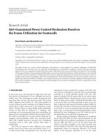
Figure 4 illustrates the timing of sending RTS/CTS using
the maximum power level, p
max
, and DATA and ACK packets
using the lowest possible power level, p
desired
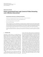
. Figure 5 shows
an example of radio range, where the transmit power level for
RTS/CTS is 30 mW and the lowest acceptable transmit power
level for DATA/ACK is 1 mW.
In BPCMP, the desired power level for transmitting
DATA/ACK is determined after RTS/CTS handshake. The
procedures for a complete transmission cycle are described
as follows.
(1) The transmitter sends RTS packets using the maxi-
mum possible power level p
max
.
(2) The receiver receives the RTS at signal power p
rec
,and
calculates the minimum desired transmit power le vel
p
data
for transmitting data packets as follows:
p
data
=
p
max
p
rec
× Rx
thresh
,(1)
where Rx
thresh
is the lowest acceptable received signal
strength. Then, the receiver marks the minimum de-
sired transmit power level in the control message field
of CTS and sends CTS back to the transmitter.
(3) Once having received CTS, the transmitter begins to
transmit data packet using the power level p
data
.
(4) The receiver sends back an ACK as soon as it receives
DATA. The transmitting power level for sending ACK
is determined in a similar way as done for DATA.
2.2.2. Problems with BPCMP
There are several problems w ith BPCMP. (1) Using the fixed
transmitting power le vel, p
max
, for RTS/CTS is not energy
efficient since the distance between the transmitter and the
receiver may change from time to time. (2) The transmis-
sion at maximum possible power level causes to interfere
other existing radio applications. (3) Different transmitting
power levels result in asymmetr ic topologies, and thus may
consume more energy [4]. Furthermore, the BPCMP was
proposed under the assumption that signal attenuation be-
tween tr ansmitters and receivers is kept the same in both
4 EURASIP Journal on Wireless Communications and Networking
Transmi t ter
Receiver
P
max
P
desired
Power levels
0
DA T A
ACK
RTS
CTS
Figure 4: Timing diagram of different power level in BPCMP.
DA T A
ACK
RTS
CTS
Range of 1 mW
AB
Figure 5: Ranges of different power levels in BPCMP.
transmission directions. It may make the communications
unreliable if the assumption is not held.
In summary, the BPCMP adopts the maximum possi-
ble transmitting power level for sending RTS/CTS packets
and the minimum desired transmitting power level for send-
ing DATA/ACK packets for implementing power control in
MANETs. As indicated by our simulation results, it does not
work so well in terms of energy efficiency. In addition, it de-
grades the overall network capacity.
3. AUTONOMOUS POWER CONTROL MAC PROTOCOL
In this section, we propose a novel autonomous power con-
trol MAC protocol that can adjust the transmitting power for
DATA/ACK packets as well as RTS/CTS packets according to
the current network condition in order to reduce the energy
consumption whereas the performance of the whole network
should not be much sacrificed. The main idea for the pro-
tocol is to use an appropriate power levels for transmitting
DATA/ACK packets and the RTS/CTS packets followed. We
will show through simulation that the new protocol is more
energy efficient and more spatial reusable than BPCMP (ba-
sic power control MAC protocol), and at the same time it is
simple to be implemented. In the sections below, we explain
the consideration and the design of the proposed MAC pro-
tocol.
One of the salient features of a MANET is its dynamic
network topology. As mobile nodes may move randomly in
a MANET, the distances between transmitters and receivers
may change arbitrarily. The transmitting power level should
be adjustable depending on the distance. Existing BPCMP
adjusts the transmitting power for sending DATA and ACK
packets to a minimum required level. However, it still needs
a fixed maximum possible power level to transmit RTS and
CTS packets. Since the network topology changes dynami-
cally, the power level for sending RTS and CTS also needs to
be adjusted according to the current node density. The ap-
propriate power level brings in several advantages, such as
energy saving, spatial reuse, and collisions reduction.
Using the adjustable transmitting power level, however,
may result in different power levels used by different trans-
mitters in the network. It may in turn cause excessive col-
lisions. Furthermore, it seems that it is impossible to have
the optimal transmitting power level according to global net-
work condition dynamically. Here we try to adjust the trans-
mitting power level locally within a local neighboring node
group and to have an approximately similar power level for
all the neighboring nodes. In the proposed protocol, trans-
mitting power level for a local node group is adjusted to an
approximately similar value in two ways. One is to adopt
an appropriate power level for tr ansmitting DATA/ACK, de-
pending on the average distance from the transmitter to all
current neighbors. The other one is to adjust the power level
for transmitting next RTS/CTS to a value proportional to the
DATA/ACK power level. Thus the energy consumption can
be reduced by collisions avoidance.
In a MAC protocol, we note that the distance can be es-
timated by using the transmitting power level at a transmit-
ter and the actual received signal power level at a receiver.
Thus, bidirectional links between transmitters and receivers
can be ensured, as long as the transmitters/receivers trans-
mit packets using some suitable power level, at which the re-
ceivers/transmitters can receive the same signal power level.
Using the estimated distance infor mation, the adjust power
level could be calculated.
Furthermore, the power control should also be con-
ducted in conjunction with routing, since it needs to keep
connectivity. Conversely, routing depends on power control
since the available coverage of transmitters depends on the
transmitting power levels. A key feature of a wireless chan-
nel is that it is a shared medium. An excessively high power
level causes excessive interference. This consequently reduces
the traffic carrying capacity of the network in addition to
reduced battery life time. Therefore, it is desirable to use a
transmitting power level as low as possible [7].
Based on aforementioned considerations, in our protocol
the transmitting power for sending RTS/CTS packets should
be adjusted to a level just slightly higher than that required
for transmitting DATA/ACK packets. On the other hand, to
Hsiao-Hwa Chen et al. 5
guarantee connectivity of the network, we increase the t rans-
mitting power level gradually if it is too low to reach any
other node.
3.1. Calculation of transmitting power level
In the proposed power control MAC protocol, the distance
information is used to determine the transmitting power
level. Assume that the noise level at a receiver is lower than
the signal level. It is common to model signal attenuation by
d
1/k
,whered is the distance between a transmitter and a re-
ceiver and k is a coefficient for k
≥ 2. Thus, the distance d
can be estimated by
d
=
k
p
∗
RTS/CTS
α
p
rec
,(2)
where p
RTS/CTS
is the transmitting power level for the
RTS/CTS packet, p
rec
is the received signal power level, and
α is a constant depended on the antenna gain, system loss,
and wavelength, and so forth. For brevit y, we set α
= 1inthe
paper.
For a given transmitter, suppose that there are already
m
− 1 mobile nodes being its neighboring nodes (i.e., it can
send data directly without passing through a relaying neigh-
boring nodes). For the implementation, we can let the trans-
mitter to keep the most current m
−1 records of the estimated
distances to its m
− 1 neighbor nodes, respectively. Now con-
sider that the transmitter wants to send a data packet to
another mobile node, namely, the mth node. At first, the dis-
tance from the transmitter to the mth mobile node is esti-
mated. Then, the average estimated distance from the trans-
mitter to the m mobile nodes (neighbors) is calculated as
follows:
d =
1
m
m
i=1
d
i
,(3)
where d
i
is the estimated distance from the transmitter to the
ith neighbor.
The power level for transmitting DATA or ACK, p
data/ack
,
from the transmitter to the mth neighbor is determined by
p
data/ack
= d
k
× Rx
thresh
,(4)
where Rx
thresh
is the minimum necessary received signal
strength.
Note that in the proposed protocol, p
data/ack
from the
transmitter to the mth neig hbor is determined depending
on average estimated distance
d instead of d
m
. For the case
d
m
> d, the transmitter may have to cancel the transmission
to the mth mobile node directly due to the insufficient trans-
mitting power level and the data packet has to be transmitted
via one of its neighbors, which is closer to it. The reason for
using the average estimated distance
d is trying to obtain a
similar power level for the data packet transmission to all m
mobile nodes and the packet is routed by shorter hops.
In the proposed protocol, the transmitting power level
for the next RTS/CTS, p
RTS/CTS
is given as follows:
p
RTS/CTS
= p
data/ack
× c,(5)
where c is a parameter related with the network situation,
and c>1.
It is to be noted that changing the power le vel for
RTS/CTS will affect the number of neighbors seen by each
transmitter, and thus the number of neighbors it has to con-
tend with for medium access. At the same time, changing the
radio coverage range of a transmitter will change the num-
ber of hops in routing, and consequently the amount of traf-
fic that each node has to carry. The parameter c may depend
on the local node density and traffic load. When the node
density is larger, for example m>5, it is reasonable to have
asmallervalueofc. Otherwise, we should set a larger value
for c.
3.2. APCMP algorithm
The algorithm carried out in the APCMP consists of four
major steps as introduced below.
(1) First, a transmitter sets the values of p
RTS/CTS
(also
denoted by p
RTS
T
)andp
ack
R
, which is stored in the routing
table, into the RTS packet, where p
ack
R
is the transmitting
power level for the receiver to transmit ACK. If the value of
p
RTS
T
is NULL (which means that it is not available), it will
be set to the value of the current transmitter’s power level
for transmitting DATA (i.e., p
data
). Then the transmitter will
send the RTS using the tr ansmitting power level p
RTS/CTS
.
In the receiver’s side, the receiver will receive the RTS
packet by power level p
rec
and obtain p
RTS
T
and p
ack
R
carried
in RTS packet. With these values, it can calculate the desired
power level p
data
T
for transmitting DATA packets as follows:
p
data
T
=
p
RTS
T
p
rec
× Rx
thresh
. (6)
The receiver estimates the distance from the current trans-
mitter by using p
ack
R
. With the estimated distance informa-
tion, new power level p
data/ack
and p
RTS/CTS
for the receiver is
calculated from (4)and(5). The value p
RTS/CTS
is set as the
new p
RTS/CTS
for the receiver. Then, the receiver sends the val-
ues of p
RTS/CTS
(as p
CTS
R
)andp
data
T
in the CTS packet to the
transmitter with the new power level p
RTS/CTS
.
(2) The transmitter receives the CTS packet by p
rec
and
obtains the values of p
CTS
R
and p
data
T
carried in the CTS
packet. The desirable power level p
ack
R
for the receiver to
transmit ACK packet is obtained from
p
ack
R
=
p
CTS
R
p
rec
× Rx
thresh
. (7)
The transmitter calculates and saves the estimated distance
to the current receiver d
r
. The average distance d to all the
neighbors that have been stored recently is calculated. Then,
it can calculate p
data/ack
, p
RTS/CTS
and set p
RTS/CTS
as the new
p
RTS/CTS
. After that, the transmitter begins to transmit data
using p
data/ack
.
6 EURASIP Journal on Wireless Communications and Networking
Table 1: The network components and parameters for a mobile
node using a modified CMU’s wireless model.
phyType Phy WirelessPhy
antType Antenna/OminiAntenna
ifqType Queue/DropTail/PriQueue
MacType Set to 3 MAC protocols, respectively
addressType Flat
adhocRouting
DSDV (destination-sequenced
distance vector)
Max. transmit power 281.8mW
Radio range of Max power 250 m
Max packet in ifq 50
Channel width 2 Mbps
(3) If the transmitter does not receive CTS packet after
a time out, it will increase the power level for transmitting
RTS/CTS to a predefined value and send RTS again.
(4) The receiver will send back the ACK packet using the
power level p
data/ack
after receiving the data packet. When
the transmitter receives ACK before the time out expires,
the t ransmission cycle is finished successfully. Otherwise, the
transmitter will t ransmit again in a similar way up to the
maximum retransmission times.
4. PERFORMANCE EVALUATION
The performance of APCMP is evaluated through computer
simulation. At first, we implement autonomous power con-
trol MAC protocol by NS-2 (network simulator version 2)
[5] (v2.27), which is a discrete event-driven simulator. The
NS-2 is widely used for MANETs research. Some existing
MAC protocols used in MANETs, such as IEEE 802.11, have
been also implemented in it. The NS-2 was developed in
two languages, C++ and OTcl. C++ language runs faster but
is difficult to debug, making it suitable mostly for detailed
protocol implementation. On the other hand, the OTcl runs
much slower but is easier to modify, making it ideal for sim-
ulation configuration and setup. Currently, the NS-2 runs in
Unix/Linux operating system. In our simulation it was in-
stalled into a Linux-like environment on Windows XP oper-
ating system, which is provided by Cygwin [8].
4.1. Simulation models
A modified CMU’s wireless model [9] for MANETs was used
as a basic wireless interface model. The network components
and parameters for a mobile node are listed in Tab le 1.
In order to thoroughly simulate a new protocol for
MANETs, it is important to use a mobility model that ac-
curately represents the mobile nodes. In our simulation,
the node movements are modeled by the random waypoint
(RWP) model [10], which was developed by CMU and has
been popularly used in the simulation of MANETs. The RWP
is a simple synthetic mobility model based on random di-
rections and speeds to realistically represent the behaviors of
mobile nodes.
In the RWP model, each node chooses uniformly at ran-
dom a destination node in a rectangular region. A node
moves to this destination with a velocity chosen at random
uniformly in the predefined interval (i.e., (min. speed, max.
speed)). When it reaches the destination, it remains static for
a pause time and then starts moving again according to the
same rule. It has been observed in [11, 12] that the spatial
distribution of mobile nodes according to the RWP model is
nonuniform. For the cases where a node can remain static for
the entire simulation time, the pause time is predefined as a
constant in our simulation.
The traffic is modeled by CBR (constant bit rate) packet
flows with fixed generation rate of ten packets per second.
The size of a CBR packet is 512 kB, and it becomes 20 kB
larger after a routing header is added in case of DSDV
(destination-sequenced distance vector) routing. The max-
imum packet number for a session is set to 10 000. And the
transmitter and the receiver of a CBR session are chosen ran-
domly among the nodes. The starting time of a session is also
randomly chosen between 0 and 200 seconds, so a session al-
ways finishes at the end of the simulation. The trafficload
varies by increasing the number of CBR sessions. For exam-
ple, 10 CBR sessions will be generated when the number of
nodes is set to 20.
4.2. Performance metrics
To judge the merit of a protocol for MANETs, three common
qualitative metrics are used in our performance evaluation as
explained below.
(i) Delivery ratio: it is ratio of the number of data pack-
ets correctly delivered out of the total number of data
packets sent. In fact it is an external measure of con-
nectivity performance. This value (always less than
one) should be as large as possible.
(ii) Throughput: it is the number of data bits delivered per
second. It also implies the performance of network ca-
pacity. The higher the value is, the better the perfor-
mance becomes.
(iii) Rate of energy efficiency: it is the number of data bits
delivered per joule energy consumed, which indicates
the energy efficiency. The higher the rate means the
more energy efficient.
4.3. Simulation results
The proposed APCMP protocol has been compared with
IEEE 802.11 and BPCMP based on the aforementioned three
metrics for performance evaluation. The effects of the num-
ber of nodes and the maximum moving sp eeds are studied.
The results are plotted in the figures with respect to the above
three per formance metrics.
4.3.1. Effects of number of nodes
First, we study the effects of number of nodes in a MANET.
The parameter setting is generated as fol lows. Nodes are
placed in a 500 m
× 500 m square area. The constants, k, c,
Hsiao-Hwa Chen et al. 7
Table 2: The number of nodes and tr affic sessions for simulation
runs in scenario 1.
Numberofnodes 246810
Number of CBR sessions 1 2 3 4 5
and m used in the proposed protocol are set to be 2, 1.2, and
5, respectively. The random way point model with pause time
being two seconds was used to model the node movements.
And the maximum speed of each node is set to be zero and
ten m/s, respectively. Total simulation time for each scenario
is 221 seconds. The number of nodes and traffic sessions are
listed in Ta ble 2.
The simulations were carried out for IEEE 802.11 MAC
protocol, BPCMP, and APCMP, respectively. Figures 6, 7,and
8 plot the results when nodes do not move, while Figures 9,
10,and11 provide results when the maximum node moving
speed is 10 m/s. All the simulation results were obtained w ith
95% confidence interval.
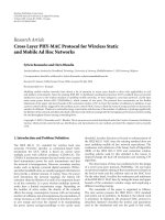
Figure 6 shows that when nodes keep static and the num-
ber of nodes and traffic increase, our protocol (denoted by
the line for “proposed”) keeps a high delivery ratio that can
be higher than 0.99, which is very close to IEEE 802.11.
Whereas the BPCMP performs the worst in delivery ratio,
whichcanreachtoabout0.94. For the throughput, there
is not much difference among the three protocols as shown
in Figure 7. Figure 8 shows that the proposed protocol is the
most energy efficient one, where the energy consumption of
APCMP protocol is about 83% of the BPCMP protocol, and
only about 49% of the 802.11 protocol.
When the node mov ing speed is 10 m/s, the delivery ra-
tio of the proposed protocol is a little lower than that of the
802.11 MAC protocol, especially when the number of nodes
increases to 10, as shown in Figure 9. The reason is that, as
the number of nodes increases, the node density also in-
creases and thus transmitting power le vel wil l be adjusted
autonomously to a smaller value, leading to a temporary dis-
connection between the transmitter-receiver pair, which is
too far away from each other. Therefore, the unsuccessful de-
liver y will increase if compared with the 802.11, which uses
a fixed maximum transmitting power. Nevertheless, APCMP
still per forms better than the BPCMP, which is just 95%. Al-
though the 801.11 performs a little bit better than APCMP
on the delivery ratio, it performs much worse than APCMP
on the energy efficiency rate, as shown in Figure 11.From
Figure 11, the rate of energy efficiency of the 802.11 is still the
worst one. For more details, it is shown that the energy effi-
ciency of APCMP is about 20% higher than that of BPCMP
and 120% higher than that of 802.11 protocol. Figure 10
plots that the throughput of three protocols is close to each
other.
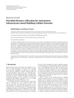
4.3.2. Effects of the maximum node moving speed
Here we study the effects of the maximum node moving
speed as it increases from zero to 21 m/s. The parameter
setting is the same as that in Section 4.3.1 except the follow-
ings: (1) nodes are placed in a 1000 m
× 1000 m square area;
108642
Number of nodes
0.94
0.95
0.96
0.97
0.98
0.99
1
1.01
Delivery ratio
APCMP
BPCMP
802.11
Figure 6: Comparison of delivery ratio (max. moving speed = 0).
108642
Number of nodes
0
5
10
15
20
25
×10
4
bps
APCMP
BPCMP
802.11
Figure 7: Comparison of throughput (moving speed = 0).
108642
Number of nodes
0
20
40
60
80
100
×10
4
Bits/joule
APCMP
BPCMP
802.11
Figure 8: Comparison of energy efficiency (moving speed = 0).
8 EURASIP Journal on Wireless Communications and Networking
108642
Number of nodes
0.9
0.92
0.94
0.96
0.98
1
1.02
Delivery ratio
APCMP
BPCMP
802.11
Figure 9: Comparison of delivery ratio (max. moving speed =
10 m/s).
108642
Number of nodes
0
5
10
15
20
25
×10
4
bps
APCMP
BPCMP
802.11
Figure 10: Comparison of throughput (max. moving speed =
10 m/s).
(2) the number of nodes is set to be 20; and (3) the num-
ber of CBR sessions is set to be ten. The simulation results of
deliver y ratio, throughput, and rate of energy efficiency are
shown in Figures 12, 13,and14,respectively.Theconfidence
interval is 95% in the simulations.
It is known from Figures 12 and 13 that the delivery ra-
tio and throughput of our protocol is better than BPCMP
but worse than 802.11, being about 118% of BPCMP and
90% of 802.11. In addition, it is to be noted that the deliv-
ery ratio and throughput decrease in general as node moving
speed increases from zero to 12 m/s, as shown in Figures 12
and 13. However, when speed increases further from 12 m/s
to 18 m/s, all the three protocols perform better. It is reason-
able as faster node movements may generate more successful
transmissions [13].
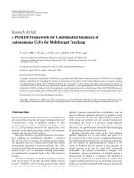
Figure 14 shows the ratio energy efficiency as node mov-
ing speed increases. APCMP protocol performs again the
best, being about 60% of that for BPCMP and 73% of that
for 802.11. It it seen from Figure 14 that BPCMP performs
108642
Number of nodes
0
20
40
60
80
100
×10
4
Bits/joule
APCMP
BPCMP
802.11
Figure 11: Comparison of energy efficiency (max. moving speed =
10 m/s).
211815129630
Max. moving speed (m/s)
0.4
0.5
0.6
0.7
0.8
0.9
1
Delivery ratio
APCMP
BPCMP
802.11
Figure 12: Comparison of delivery ratio (number of nodes: 20,
CBR: 10).
really badly as node moving speed increases and the number
of nodes increases. It consumes more energy even than IEEE
802.11; whereas APCMP protocol is very robust in such a
network scenario and provides the best energy saving per-
formance.
In summary, the proposed APCMP protocol offers su-
perb performance in terms of energy efficiency and mobility
support and in particular suits applications in MANETs. Be-
sides, APCMP protocol is simple to implement and can be
incorporated easily into popular IEEE 802.11 protocol.
5. CONCLUSION
To reduce energy consumption is of great importance for
providing QoS assurance in MANETs. The focus of this pa-
per is on the design of power control MAC protocol for
MANETs. A brief introduction of IEEE 802.11 MAC proto-
colandbasicpowercontrolMACprotocolforMANETsmo-
tivated us to propose a simple and yet efficient autonomous
Hsiao-Hwa Chen et al. 9
211815129630
Max. moving speed (m/s)
55
75
95
115
135
155
175
195
215
×10
3
bps
APCMP
BPCMP
802.11
Figure 13: Comparison of throughput (number of nodes: 20, CBR:
10).
211815129630
Max. moving speed (m/s)
0
5
10
15
20
25
×10
4
Bits/joule
APCMP
BPCMP
802.11
Figure 14: Comparison of energy efficiency (number of nodes: 20,
CBR: 10).
power control MAC protocol (APCMP), in which transmit-
ting power can be adjusted autonomously to an appropriate
level according to network condition. The APCMP protocol
has been evaluated by simulations under NS-2 and compared
with other MAC protocols. It has b een shown from the simu-
lation results that APCMP protocol offers a very good energy
efficiency and throughput under various mobility scenarios
and is in particular suitable for the applications in MANETs.
ACKNOWLEDGMENTS
TheworkreportedinthispaperwassupportedpartlybyRe-
search Grants NSC 94-2213-E-110-014 and NSC 94-2213-E-
110-013. The work of Jie Li has been supported in part by
JSPS under Grant-in-Aid for Scientific Research.
REFERENCES
[1] Internet Engineering Task Force (IETF) Mobile Ad Hoc
Networks Working Group Charter, />charters/manet-charter.html.
[2] B. Chen, K. Jamieson, H. Balakri shnan, and R. Morris, “Span:
an energy-efficient coordination algorithm for topology main-
tenance in ad hoc wireless networks,” in Proceedings of 7th A n-
nual International Conference on Mobile Computing and Net-
working (MOBICOM ’01), pp. 85–96, Rome, Italy, July 2001.
[3] J. Gomez, A. T. Campbell, M. Naghshineh, and C. Bisdikian,
“Conserving transmission power in wireless ad hoc networks,”
in Proceedings of the 9th International Conference on Network
Protocols (ICNP ’01), pp. 24–34, Riverside, Calif, USA, Novem-
ber 2001.
[4] E S. Jung and N. H. Vaidya, “A power control MAC protocol
for ad hoc networks,” in Proceedings of the 8th Annual Interna-
tional Conference on Mobile Computing and Networking (MO-
BICOM ’02), pp. 36–47, Atlanta, Ga, USA, September 2002.
[5] The Network Simulator—NS-2, 2004, />nsnam/ns/.
[6] Institute of Electrical and Electronics Engineers, USA, IEEE
802.11 Draft Standard for Wireless LAN: Medium Access Con-
trol and Physical Layer Specification, draft p802.11d5.0 edi-
tion, July 1996.
[7] P. Gupta and P. R. Kumar, “The capacity of wireless networks,”
IEEE Transactions on Information Theory,vol.46,no.2,pp.
388–404, 2000.
[8] .
[9] The CMU Monarch Project, The CMU Monarch Project’s
Wireless and Mobility Extensions to NS.
[10] C. Bettstetter, G. Resta, and P. Santi, “The node distribution of
the random waypoint mobility model for wireless ad hoc net-
works,” IEEE Transactions on Mobile Computing,vol.2,no.3,
pp. 257–269, 2003.
[11] C. Bettstetter, “Mobility modeling in wireless networks: cate-
gorization, smooth movement, and border effects,” ACM Mo-
bile Computing and Communications Review, vol. 5, no. 3, pp.
55–67, 2001.
[12] C. Bettstetter and O. Krause, “On border effects in modeling
and simulation of wireless ad hoc networks,” in Proceedings of
IEEE International Conference on Mobile and Wireless Commu-
nication Networks (MWCN ’01), Recife, Brazil, August 2001.
[13] M. Grossglauser and D. N. C. Tse, “Mobility increases the ca-
pacity of ad hoc wireless networks,” IEEE/ACM Transactions
on Networking, vol. 10, no. 4, pp. 477–486, 2002.
Hsiao-Hwa Chen is currently a Full Pro-
fessor in National Sun Yat-Sen Univer-
sity, Taiwan. He has authored or coau-
thored over 150 technical papers in ma-
jor international journals and conferences,
and four books, and three book chap-
ters in the areas of communications. He
served as a TPC Member and Sympo-
sium Chair of major international con-
ferences, including IEEE VTC, IEEE ICC,
IEEE Globecom, IEEE WCNC, and so forth. He served or is
serving as an Editorial Broad Member or/and Guest Editor for
IEEE Communications Magazine, IEEE Transactions on Wireless
Communications, IEEE Vehicular Technology Magazine, Wireless
Communications and Mobile Computing (WCMC) Journal and
International Journal of Communication Systems, and so forth.
10 EURASIP Journal on Wireless Communications and Networking
He has been a Guest Professor of Zhejiang University, Shanghai Jiao
Tung University, China.
Zhengying Fan was born in Shaanxi, China.
She received her B.S. degree in electronic
sciences from Northwest University, China,
in 1999, and her M.S. degree in information
sciences and electronics from the University
of Tsukuba, Japan, in 2005. Currently she is
with the Tech. Department of FDC Inc. Ltd.
Co, Japan.
Jie Li received the B.E. degree in com-
puter science from Zhejiang University,
Hangzhou, China, in 1982, the M.E. degree
in electronic engineering and communica-
tion systems from China Academy of Posts
and Telecommunications, Beijing, China, in
1985. He received the Dr. Eng. degree from
the University of Electro-Communications,
Tokyo, Japan, in 1993. Since April 1993, he
has been with University of Tsukuba, Japan.
He has been an Associate Professor since 1997. His research inter-
ests are in mobile distributed multimedia computing and network-
ing, OS, network security, modeling, and performance evaluation
of information systems. He received the Best Paper Award from
IEEE NAECON’97. He is a Senior Member of IEEE, and a Mem-
ber of ACM. He has served as a secretary for the Study Group on
System Evaluation of the Information Processing Society of Japan
(IPSJ) and on several editorial boards for IPSJ (Information Pro-
cessing Society of Japan) Journal, and so on, and on Steering Com-
mittees of the SIG of System EVALuation (EVA) of IPSJ, the SIG of
DataBase System (DBS) of IPSJ, and the SIG on Mobile Computing
and Ubiquitous Communications of IPSJ. He has also served on the
program committees for several international conferences such as
IEEE Infocom, IEEE Globecom, and IEEE Mass.