Báo cáo hóa học: " Routing and Power Allocation in Asynchronous Gaussian Multiple-Relay Channels" potx
Bạn đang xem bản rút gọn của tài liệu. Xem và tải ngay bản đầy đủ của tài liệu tại đây (1.04 MB, 11 trang )
Hindawi Publishing Corporation
EURASIP Journal on Wireless Communications and Networking
Volume 2006, Article ID 56914, Pages 1–11
DOI 10.1155/WCN/2006/56914
Routing and Power Allocation in Asynchronous Gaussian
Multiple-Relay Channels
Zigui Yang and Anders Høst-Madsen
Department of Electrical Engineering, University of Hawaii at Manoa, Honolulu, HI 96822, USA
Received 31 October 2005; Revised 28 April 2006; Accepted 2 May 2006
We investigate the cooperation efficiency of the multiple-relay channel when carrier-level synchronization is not available and
all nodes use a decode-forward scheme. We show that by using decode-forward relay signaling, the transmission is effectively
interference-free even when all communications share one common physical m edium. Furthermore, for any channel realization,
we show that there always exist a sequential path and a corresponding simple power allocation policy, which are optimal. Although
this does not naturally lead to a polynomial algorithm for the optimization problem, it greatly reduces the search space and makes
finding heuristic algorithms easier. To illustrate the efficiency of cooperation and provide prototypes for practical implementation
of relay-channel signaling, we propose two heuristic algorithms. The numer ical results show that in the low-rate regime, the gain
from cooperation is limited, while the gain is considerable in the high-r ate regime.
Copyright © 2006 Z. Yang and A. Høst-Madsen. This is an open access article distributed under the Creative Commons
Attribution License, which permits unrestricted use, distribution, and reproduction in any medium, provided the original work is
properly cited.
1. INTRODUCTION
A wireless ad hoc network is an infrastructureless network,
in w hich the communications between two nodes are typi-
cally maintained by the cooperation of other nodes. The tra-
ditional multihopping operation lets each intermediate node
receive information only from its immediate predecessor and
then send it to its immediate successor. A more advanced op-
eration is to use relay-channel signaling. The essential dif-
ference between the traditional multihopping and the relay-
channel signaling is that in the latter, a node uses the infor-
mation from all its upstream nodes instead of the informa-
tion from the closest one.
The relay channel was first introduced by van der Meulen
[1, 2]. In a simplest case, a relay channel has only one relay
to assist the transmission between the source and the destina-
tion. The relay channel can be denoted by (X
1
, X
2
, p(y
2
, y
3
|
x
1
, x
2
), Y
2
, Y
3
), where X
1
, X
2
are the transmitter alphabets
of the source and the relay, respectively, Y
2
, Y
3
are the re-
ceiver alphabets of the relay and the destination, respectively,
and a collection of probability p(
·, ·|x
1
, x
2
)onY
2
, Y
3
,one
for each (x
1
, x
2
) ∈ X
1
, X
2
.Herex
1
, x
2
are the channel inputs
by the source and the relay and y
2
, y
3
are the outputs of the
relay and the destination, respectively. The relay channel was
extensively studied in [3], where two cooperation schemes,
decode-forward and compress-forward, were proposed. In-
spired by a renewed interest in ad hoc networks and network
information theory, much research has been done recently
on relay channels and cooperative diversity [4–14].
We assume that every node uses a decode-forward
scheme. Although the other two relaying schemes, amplify-
forward and compress-forward, can achieve higher rates un-
der certain channel realizations [4, 6, 7], they are difficult
to scale to large networks. In an amplify-forward scheme,
the relays essentially act as analog repeaters, and therefore
enhance the system noise. Another challenge in using the
amplify-forward scheme in large networks is the difficulty
of implementing routing algorithms. Compress-forward re-
quires complex Wyner-Ziv coding, which is difficult to be
implemented in practice [15], especial ly when scaled to large
networks. Decode-forward has its own drawback in that it re-
quires full decoding at each relay, and therefore may cause er-
ror propagation. However, this can be compensated by s trong
channel coding.
The achievable rate of a one-relay channel using a
decode-forward scheme is [3]
R
≤ max
P(x
1
,x
2
)
min
I
X
1
; Y
2
| X
2
, I
X
1
, X
2
; Y
3
. (1)
The interpretation is that the relay first fully decodes the
message from the inputs of the source, which results in the
first term in the min
{·} function, and then the destination
decodes the messages from the inputs of both the source
and the relay, and thus gives the second term in the min
{·}
2 EURASIP Journal on Wireless Communications and Networking
function. An adaptive transmission scheme will allow the
source to communicate directly with the destination if the
relay has a poor link to the source—one form of routing. It
then gives the following achievable rate:
R
≤ max
P(x
1
,x
2
)
max
min
I
X
1
; Y
2
| X
2
, I
X
1
, X
2
; Y
3
,
I
X
1
; Y
3
| X
2
.
(2)
For a physically degraded channel, that is, when X
1
→
(X
2
, Y
2
) → Y
3
forms a Markov chain, (1) achieves the ca-
pacity. However, for a general relay channel, the capacity is
unknown even for one-relay case. Therefore, most of the re-
search on multiple-relay channels concentrated on achiev-
able rates and capacity bounds [5, 6, 8, 16] or on the capac-
ity for some special type of multiple-relay channels such as
the degraded multiple-relay channel [17]. A multiple-relay
channel is generally a multilevel structure, in which each level
contains one or more nodes and the nodes in the same level
decode a message at the same time.
The wireless communication broadcast property is re-
ferred to as “wireless multicast advantage” (WMA) or “wire-
less broadcast advantage” (WBA) and may be used in the
routing algorithm in wireless networks to reduce power con-
sumption and improve reliability [18, 19]. If different trans-
mitters can be synchronized at car rier level and thus are able
to coordinate to use beamforming techniques, it is shown
that cooperation achieves significant gain in reducing to-
tal power consumption [20]. Relay-channel signaling further
exploits the broadcast transmission and multiaccess recep-
tion properties by allowing a node to accumulate the soft in-
formation of all its received signals, that is, a node’s decoding
may depend on multiple received signals. Although it is ob-
vious that relay-channel signaling can further improve the
performance, it is at the cost of higher complexity. One fun-
damental question is whether it pays off using relay-channel
signaling or not. In this paper, we will investigate the cooper-
ation efficiency in the multiple-relay-channel setting. Specif-
ically, we consider the quasistatic Gaussian wireless multiple-
relay channel.
A quasistatic channel here means that the channel real-
ization remains unchanged during the transmission of one
message and goes to another independent realization in the
transmission period of the next message. One useful mea-
sure of the performance in this scenario is outage probabil-
ity, which is the probability that the channel cannot support
a particular communication rate under certain constraints.
The quasistatic model is suitable for delay-sensitive services
that have strict delay requirements. For delay-insensitive ser-
vices, the source and the relay may choose to adjust their
transmission rate according to the channel condition [7]. In
many applications such as sensor networks, the nodes typ-
ically operate on limited-energy batteries, which are usually
not rechargeable or replaceable, and thus results in severe en-
ergy constraints. A main concern is therefore optimizing en-
ergy consumption in the network.
Consider at first a simple point-to-point channel in Ray-
leigh fading with a channel gain h.Ifitisdesiredtotrans-
mitatacertainconstantrateR, the required power is
proportional to h
−2
and the average power is proportional
to E[h
−2
], which can be shown to be infinite. Thus, it is im-
possible to transmit in all channel conditions, and a thresh-
old h
0
has to be chosen so that if h<h
0
, no transmission
is done and an outage is declared. Equivalently, a threshold
power P
0
can be set so that if the required power P for trans-
mission at rate R is larger than P
0
, transmission is given up
and an outage is declared. The average power consumption
is an increasing function of P
0
, while the outage probabil-
ity is a decreasing function of P
0
, which should therefore be
chosen as a compromise between power consumption and
acceptable outage probability. Notice that P
0
is not related to
the physical power constraint of the transmission circuit of
the terminal, although of course P
0
must be chosen less than
this.
Generalizing this to networks, we consider a total power
constraint, that is, at any time, the overall power consump-
tion cannot exceed a particular amount of power P
0
. This
seems the most reasonable point of view: if the total power
(energy) needed in the network exceeds a certain thresh-
old, transmission is given up. A precise statement of this is
as follows. Assuming that the source-destination pair in the
multiple-relay channel wants to maintain a constant com-
munication rate R,wedefineanoutageeventforagiven
transmission scheme T and the channel realization H as
E
1
: R
T
P
0
, H
≤ R,(3)
where R
T
(P, H ) is the maximal rate that the transmission
scheme T can achieve for the channel realization H with a
total power consumption of at most P
0
. For all reasonable
transmission schemes T , R
T
(P, H ) is a nondecreasing func-
tion of P.WedefineP
T
(R, H) as the minimum total power
required by transmission scheme T to achieve the rate R for
the channel realization H. Then the outage event is equiva-
lent to the event
E
2
: P
T
(R, H) >P
0
. (4)
Therefore, we can minimize outage probability by minimiz-
ing the total power needed to achieve the target rate R for
each channel realization. T his problem was investigated for
parallel (two-hop) relay channels in [21, 22]. Here we gen-
eralize this to multihop channels where arbitrary interrelay
communication is allowed. The problem then becomes more
complicated, requiring finding both an optimal arrangement
of nodes and a corresponding power allocation policy.
Apart from the above overall power constraint, individ-
ual node power constraints may also be relevant. Firstly, the
power allocation can result in uneven power consumption
among the nodes. However, with channel variations, this is
averaged out; furthermore, if all nodes at sometime or other
act as source-destination pairs, the power consumption can
be expected to be fairly distributed. Secondly, the power al-
location could result in a solution where an individual node
power consumption is above what the node is physically ca-
pable of. However, taking this into account would just com-
plicate the solution without giving further insight.
The rest of the paper is organized as follows. In Section 2,
we give the model for the Gaussian multiple-relay channel,
Z. Yang and A. Høst-Madsen 3
for which we will find an optimum arrangement of nodes,
shown to be a sequential path, and its corresponding opti-
mal power allocation policy is given in Section 3.Toinves-
tigate the performance of the relay-channel signaling and to
provide some prototype algorithms for practical implemen-
tation of relay-channel signaling, we provide two heuristic
algorithms for the cooperative relay-channel signaling prob-
lem in Section 4.InSection 5, we extend our discussion to
the case when nodes have only limited signal processing ca-
pability. The numerical results are provided in Section 6 and
a brief summarization is given in Section 7.
2. CHANNEL MODEL
In this paper, we consider a quasistatic multiple-relay chan-
nel with N nodes, numbered from 1 to N. Without loss of
generality, we assume that 1 and N is the source-destination
pair and that the other nodes act as relays. We assume that all
nodes operate in full-duplex mode, and thus they can receive
and transmit in the same frequency band at the same time.
Full-duplex communication is generally regarded as difficult
to achieve in practice, but there are techniques that make it
possible [23].
Another important assumption is on synchronization
among nodes. There are three levels of synchronization:
frame, symbol, and carr ier. We assume that the receivers
are completely synchronized at all levels. For transmitters,
it is realistic to assume that frame- and symbol-level syn-
chronizations are available. The contentious point is on
carrier-level synchronization, which requires that separate
microwave oscillators at different nodes are synchronized.
This seems highly unrealistic. Left by themselves, the drift
of the oscillators makes synchronization impossible. It might
be possible to couple oscillators, and ver y closely spaced
nodes could even autocouple, but this requires nontrivial mi-
crowave innovation, and in general this seems quite improb-
able especially for sensor networks with simple nodes. We
will therefore assume that there is no carrier synchroniza-
tion. The link between any pair of nodes (i, j)canbepa-
rameterized by a complex channel gain h
ij
, which is assumed
to be symmetric, that is, h
ij
= h
ji
. The channel gains h
ij
are independent random variables as a result of the random
movement of nodes and (or) fading. They are assumed to
be fixed during one-message transmission period and go to
another independent realization in the next-message trans-
mission period.
The source wants to send a message w to the destination
during the duration of each channel realization H
={h
ij
:
i, j
∈{1, , N}, i = j}.LetX
i
(k), i ∈{1, , N − 1},
be the channel input of node i at time k and let Y
j
(k),
j
∈{2, , N}, be the channel output of node j at time k,
we have
Y
i
(k) =
j∈{1, ,N−1}, j=i
h
ij
X
j
(k)+Z
i
(k), i ∈{2, , N},
(5)
where Z
i
(k) ∼ CN (0, 1) are i.i.d. unit power white Gaus-
sian noises for all i, k. We assume that full channel state
information is available noncausally to all nodes. While this
may not be realistic in fast-changing channels, it is possi-
ble if the channel is not varying too quickly. Furthermore,
this gives a bound on performance as for the case when less
knowledge is available.
3. ACHIEVABLE R ATES OF THE GAUSSIAN
MULTIPLE-RELAY CHANNEL
In [5], Gupta and Kumar demonstrated an achievable region
for a multiple-relay channel, and later Xie and Kumar [16]
established an explicit formula for the achievable rate, which,
in general, exceeds the rate in [5]. Here we restate the theo-
rem i n [16] as follows.
Theorem 1 (see [16, Theorem 3.4]). For a discrete memory-
less multiple-relay channel with source node 1, destination node
N, and the other nodes arranged into L
−1 levels with each le vel
k consisting of a set of nodes Γ
k
, k = 1, , L − 1, the following
rate is achievable:
R< max
P(X
0
, ,X
L−1
)
min
1≤k≤L
min
i:i∈Γ
k
I
X
0
, , X
k−1
; Y
i
| X
k
, , X
L
,
(6)
where boldface characters de n ote vectors for inputs of the nodes
in each group. Here Γ
0
:={1} and Γ
L
:={N}.
For an asynchronous Gaussian multiple-relay channel,
we have the following corollary of Theorem 1.
Proposition 1. Assume that node j uses transmission power
P
j
. For an asynchronous Gaussian multiple-relay channel with
L
− 1 levels of relay nodes, the following rate is achievable:
R
≤ min
1≤l≤L
min
i∈Γ
l
1
2
log
1+
l−1
m=0
j∈Γ
m
P
j
h
ij
2
. (7)
Proof. The message w is first split into B blocks w
1
, , w
B
of nR bits each. Each node i generates a codebook with 2
nR
i.i.d. n-sequences with i.i.d. Gaussian components and index
them as x
i
(w
j
), w
j
∈{1, ,2
nR
}. The whole transmission
is performed in B + L
− 1 time slots, and thus the overall
rate is R
· B/(B + L − 1) bits per channel use. By making B
large, we can get the rate arbitrarily close to R.Ineachof
the first B time slots, the source node 1 transmits the code-
word x
1
(w
i
)foreachw
i
, i ∈{1, , B}, and in the remain-
ing time slots, it transmits constant signals x
1
(1). A node i in
level k,1
≤ k ≤ L, starts the decoding of w
1
at the end of
kth time slot and sends out x
i
(w
1
) in time slot k +1.Itcon-
tinues the same decoding and encoding procedure in each
time slot thereafter until it has decoded and sent out all the
messages. It transmits some constant signals x
i
(1) in the re-
maining slots. To illustrate the encoding scheme, we give an
example of a relay channel of 5 nodes, in which (1, 5) is the
source-destination pair. Nodes 2 and 3 are assigned to level 1
and node 4 is in level 2. The message w is split into 6 message
blocks. The encoding scheme is shown in Figure 1.
The relays and the destination decode each w
i
, i ∈
{
1, , B}, using similar sliding-window decoding technique
4 EURASIP Journal on Wireless Communications and Networking
Block 1
x
1
(w
1
)
x
2
(1)
x
3
(1)
x
4
(1)
Block 2
x
1
(w
2
)
x
2
(w
1
)
x
3
(w
1
)
x
4
(1)
Block 3
x
1
(w
3
)
x
2
(w
2
)
x
3
(w
2
)
x
4
(w
1
)
Block 4
x
1
(w
4
)
x
2
(w
3
)
x
3
(w
3
)
x
4
(w
2
)
Block 5
x
1
(w
5
)
x
2
(w
4
)
x
3
(w
4
)
x
4
(w
3
)
Block 6
x
1
(w
6
)
x
2
(w
5
)
x
3
(w
5
)
x
4
(w
4
)
Block 7
x
1
(1)
x
2
(w
6
)
x
3
(w
6
)
x
4
(w
5
)
Block 8
x
1
(1)
x
2
(1)
x
3
(1)
x
4
(w
6
)
Figure 1: Encoding scheme.
[6, 24]. A node i in level l can decode w
1
at the end of lth
time slot using a window of the first l received blocks. After
decoding the first message, the window is shifted by one and
the part due to the transmission of the first message is sub-
tracted from the received signals in the new window and then
the second message is decoded. It continues until all messages
are decoded. For each message, node i is actually receiving
information from l independent parallel channels [25]. Thus
for node i to successfully decode the message, we have
R< max
P(X
0
, ,X
L−1
)
I
X
0
, X
1
, , X
l−1
; Y
i
| X
l
, , X
L−1
(8)
≤
1
2
log
1+
l−1
m=0
j∈Γ
m
P
j
h
ij
2
,(9)
where P
j
is the power assigned to node j.Sinceeachnodeex-
cept for the source needs to fully decode each message block,
we have
R
≤ min
1≤l≤L
min
i∈Γ
l
1
2
log
1+
l−1
m=0
j∈Γ
m
P
j
h
ij
2
. (10)
Here for simplification of notation, we assume that
−1
k=0
t∈Γ
k
P
t
|h
it
|
2
= 0, ∀i. (11)
Remark 1. Note that we do not introduce any correlation
between the inputs of the nodes as it will not produce any
gain if no carrier-level synchronization between transmitters
is available [ 6, 7].
Remark 2. To achieve the rate in (7), all X
i
’s are Gaussian
distributed and mutually independent.
Remark 3. Ascanbeseenfrom(9), the interference from
other nodes is effectively cancelled out after a node subtracts
from its received signals the part contributed from the mes-
sages it knows. From (9), we obtain an equivalent form of
(7).
Corollary 1. Fix a rate R and define d
ij
= (2
2R
− 1)/|h
ij
|
2
.
For the rate R to be achievable, the power s P
1
, P
2
, , P
N
have
to satisfy
l−1
m=0
j∈Γ
m
P
j
d
ij
≥ 1 (12)
for all l.
3.1. The optimal multilevel structure
and power allocation policy
As we have shown, in order to minimize the outage prob-
ability in a quasistatic channel, we need to find a multilevel
structure S and a corresponding power allocation policy T(S)
such that the total power to achieve the rate requirement R is
minimized. Assuming that a multilevel structure S has L +1
levels, we denote the nodes in each level 0
≤ l ≤ L by Γ
l
and
the size of Γ
l
by |Γ
l
|.WehaveΓ
0
={1} and Γ
L
={N}.Denote
the level of a node i as (i). Note that S may not include all
the nodes, that is, some nodes may be chosen not to partici-
pate in the transmission. Denote the power assigned to node
i
∈ S by a power allocation policy T(S)forS as P
i
(T, S). We
then need to solve the following optimization problem:
min
T,S
i∈S
P
i
(T, S) such that R
≤ min
1≤l≤L
min
i∈Γ
l
1
2
log
1+
l−1
m=0
j∈Γ
m
P
j
(T, S)
h
ij
2
.
(13)
Since a Gaussian multiple-relay channel in general is not
a degraded channel as the one studied in [17], it does not
have a natural arrangement of nodes that is optimal. How-
ever,itdoeshavesomespecialpropertiesforanoptimalmul-
tilevel structure S and its corresponding optimal power allo-
cation policy T(S) as stated in the next two theorems.
Theorem 2. For any channel realization H and rate re-
quirement R, the overall power allocation is minimized by a
sequential-path multilevel structure S, that is, one with
|Γ
l
|=1
for all l.
Proof. We need to show the existence of a sequential path P
that is optimal. For any channel realization H, there always
exist a multilevel structure S and a corresponding power al-
location policy T(S) that are optimal. Assuming that S has
L + 1 le vels, we prove by induction that it can always be con-
verted to an equivalent path P without increasing total power
consumption by properly removing some nodes in S and ad-
justing transmission power of the remaining nodes.
First, for level L, Γ
L
={N},thus|Γ
L
|=1. Suppose that
for decoding orders l
≥ T +1(T<L), we have |Γ
l
|=1.
We wil l then show that we can always make
|Γ
T
|=1 without
violating the constraints. For convenience of presentation, we
denote the only node in Γ
l
, l ≥ T +1,byζ
l
.
If
|Γ
T
|=1, we are done. Otherwise, assume that |Γ
T
|=
M (M ≥ 2) and Γ
T
={t
m
:1≤ m ≤ M}. Without risk of
confusion, we simplify the notation of P
i
(T, S)toP
i
and we
have P
i
> 0, for all i ∈ S.
Z. Yang and A. Høst-Madsen 5
We consider two cases.
Case 1. There exists
{t
1
, t
2
}∈Γ
T
such that d
t
i
ζ
T+1
> 0, i =
1, 2.
We perform the following recursive power updating pro-
cedure.
(1) Fix the transmission power of all nodes that reside
in level T or higher except for t
1
and t
2
. Adjust the
transmission power P
t
1
of t
1
to P
new
t
1
= P
t
1
+ δ,whereδ
is a small value.
(2) Adjust the transmission power P
t
2
of t
2
such that
the left-hand side of the constraint (12)forζ
T+1
re-
mains unchanged. Therefore, we have P
new
t
2
= P
t
2
−
(d
t
2
ζ
T+1
/d
t
1
ζ
T+1
)δ.
(3) Adjust the transmission power of ζ
T+1
such that the
left-hand side of constraint (12) is kept the same for
ζ
T+2
to get
P
new
ζ
T+1
= P
ζ
T+1
+
d
t
2
ζ
T+1
d
ζ
T+1
ζ
T+2
d
t
1
ζ
T+1
d
t
2
ζ
T+2
−
d
ζ
T+1
ζ
T+2
d
t
1
ζ
T+2
δ. (14)
(4) Recursively update the transmission power of node
i, i
= ζ
T+2
, , ζ
L−1
, such that the left-hand side of the
constraint (12) is kept the same for the node right be-
hind it.
This recursive updating procedure guarantees that the
constraint (12) is still satisfied at all relay nodes and at the
destination. Since we vary the transmission power of only
one node at each step, the total amount of power change
is proportional to δ. Denote the total transmission power
for the multilevel structure S and the corresponding power
allocation policy T(S)asξ(S, T(S)), that is, ξ(S, T(S))
=
i∈S
P
i
(T, S). Then
ξ
S, T
new
(S)
= ξ
S, T(S)
+ f (S)δ, (15)
where T
new
is the new power allocation policy after the power
updating procedure and f (S) is a constant that does not de-
pend on δ but only on the multilevel structure S if
|δ| is small
enough. Obviously, δ isallowedtobeeitherpositiveorneg-
ative, that is, we can either increase or decrease the transmis-
sion power of t
1
.Thus,if f (S) = 0, we can always choose
the sign of δ such that the total amount of power change
f (S)δ<0, and hence
ξ
S, T
new
(S)
<ξ
S, T(S)
. (16)
This contradicts the fact that the original multilevel structure
and power allocation policy pair (S, T(S)) is optimal. There-
fore we must have f (S)
= 0, and thus (S, T
new
(S)) is also
optimal. In this case, we can repeatedly perform the same
updating procedure by decreasing the transmission power
of t
1
(or t
2
) and increasing the transmission power of t
2
(or
t
1
) until either the transmission power of node i, P
new
i
= 0,
i
∈{ζ
T+1
, , ζ
L−1
} or P
new
t
i
= 0, i = 1, 2. If P
new
i
= 0,
i
∈{ζ
T+1
, , ζ
L−1
}, then node i can be removed from the
relaying structure and we can continue the updating proce-
dure above. If P
t
i
= 0, i = 1, 2, it means that we c an remove
t
i
from the structure S.
If there still exist two or more nodes with decoding order
T, we can always take out two of them and repeat the same
procedureabovetoremoveonenodeeachtimeuntilonly
onenodeiskept.
Case 2. d
t
i
ζ
T+1
= 0, for all t
i
∈ Γ
T
\{t
1
},andd
t
1
ζ
T+1
> 0.
In this case, there is only one node t
1
in level T that has
finite-length link to node ζ
T+1
. This case is actually essentially
the same as in Case 1. Pick a node t
2
in Γ
T
, t
2
= t
1
,anda
node ζ
T+i
∈{ζ
T+2
, , ζ
L
} such that (ζ
T+i
) <(k), for all
k
∈{ζ
T+2
, , ζ
L
}, k = ζ
T+i
,andd
t
2
ζ
T+i
> 0. Then we can
perform the same recursive power updating algorithm as in
Case 1.Theonlydifference is that node ζ
T+i−1
takes the place
of t
1
in Case 1. Thus we can always reduce the power of t
2
to
0 and thus remove it from the multilevel relaying structure.
Combining our discussions of Cases 1 and 2,wecancon-
clude that we are always able to keep only one node at decod-
ing order T without increasing the total power consumption.
By induction l,forall1
≤ l ≤ L,wemayhave|Γ
l
|=1
and this establishes the proof.
Note that the new relaying path P does not necessary have
the same number of levels as S.
The implication of Theorem 2 is that we can restrict our
search to sequential paths without loss of optimality. In doing
so, we greatly reduce the search space. The following theorem
shows how power is optimally allocated given a sequential
relaying path.
Theorem 3. For a sequential relaying path P, the optimal
power allocation policy T(P) can be implemented by a recur-
sive power-filling procedure, that is, along path P, starting from
the source, each node i adjusts its t ransmission powe r such that
the constraint (12) is satisfied w ith equality sign at its immedi-
ate successor j, (j)
= (i)+1.
Proof. Let the relaying path be P
= (ζ
0
, ζ
1
, , ζ
L
), where
ζ
0
= 1, ζ
L
= N. Initially we set the power of all nodes to
0. Since node ζ
1
only receives information fr om the source
ζ
0
, we must let the source transmit at a power level such that
constraint (12) is exactly satisfied at node ζ
1
. Now the mes-
sage is known to ζ
0
and ζ
1
and only they are eligible to trans-
mit. With the objective to save transmission power, at any
time we always let the node whose transmission is most ef-
ficient (results in less total transmission power) increase its
transmission power. Now the transmission of node ζ
1
will be
more efficient. Otherwise, if the transmission of ζ
0
is more
efficient, it will increase its transmission power until a node
other than node ζ
1
satisfies constraint (12). That node can
then decode in the same decoding order as node ζ
1
and it
contradicts the fac t that there is only one node in each level.
Thus the source has to stop increasing its transmission power
as long as node ζ
1
satisfies (12). Node ζ
1
then adjusts its
power level such that ζ
2
satisfies constraint (12)withequal-
ity sign. This procedure proceeds until the destination meets
condition (12)exactly.
Here we do not need to know how to exactly determine
the efficiency of the transmission of a particular node. What
6 EURASIP Journal on Wireless Communications and Networking
we only need to know is that it depends on the structure of
the relaying path and the state of the relaying path, that is,
whether constraint (12) is satisfied at the nodes in the path or
not. Therefore, before the state of the relaying path changes,
the transmission efficiency of any node that has satisfied (12)
remains unchanged. Theorem 3 implies that every node ex-
cept for the destination transmits with certain level of posi-
tive power and every node except for the source receives ex-
actly enough information from its upstream nodes.
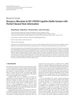
3.2. Example
Nowwegiveasimpleexampletoillustratethebenefitof
cooperative relay signaling. Figure 2 shows a multiple-relay-
channel network with 4 nodes in which (1, 4) is the source-
destination pair. The label attached to the link (i, j) is the
value d
ij
as defined before. All 4 possible sequential relaying
paths and their corresponding total power consumption are
presented in Table 1. The path 1
→ 3 → 2 → 4isnotanel-
igible relaying path as by the power allocation policy, node
2 cannot decode after node 3. The total power consumption
is calculated using the recursive power-filling procedure. For
example, for the path 1
→ 2 → 4, in order to make node
2abletodecode,wehaveP
1
= 10. To make node 4 able to
decode, we have P
1
/42 + P
2
/30 = 1, and thus P
2
≈ 22.86.
The overall power consumption is then P
1
+ P
2
= 32.86. A
traditional multihop operation that uses the shortest path al-
gorithms will find 1
→ 2 → 4astheoptimalpathwithover-
all power consumption 40. However, the transmission from
node 1 to node 2 will give rise to interference to the commu-
nications between node 2 and node 4. Therefore, the actual
power consumption will be larger than 40. From Table 1,itis
interesting to see that the best relaying path 1
→ 2 → 3 → 4
is the worst one from the point of view of traditional multi-
hopping algorithms.
4. HEURISTIC ALGORITHMS
From Theorems 2 and 3, we have shown that for any chan-
nel realization H, there exist an optimal relaying path P and
a corresponding simple power allocation policy T(P). Thus
limiting our search to sequential paths can greatly reduce the
search space for optimal solutions. There have been some ele-
gant shortest path algorithms to find a shortest path in a net-
work [ 26]. However, the Bellman pr inciple used in these tra-
ditional shortest path algor ithms is not satisfied here. For ex-
ample, consider a relay network with 4 nodes V
={1, 2, 3, 4}
and costs d
21
= 3, d
32
= 4, d
31
= 6, d
41
= 7, d
42
= 12,
d
43
= 0.1. We may verify that the optimal relaying path
is 1
→ 3 → 4. By the Bellman principle, the optimal co-
operative relaying path from 1 to 3 should be the direct
link from 1 to 3, which requires a total power consump-
tion of 34. However, from 1 to 3 we can find that the path
1
→ 2 → 3 actually requires a smaller total power consump-
tion of (10 + (34
− 10)/34 × 25) ≈ 27.65. This shows that the
Bellman principle does not apply to the cooperative routing
problem.
Another difference between the optimal relaying path
problem in this paper and the traditional shortest path
1
2
10
34
3
4
8
30
42
25
Figure 2: A multiple-relay channel with 4 nodes.
Table 1: Relaying paths and overall power consumptions.
Path Overall power
1→ 442
1
→ 2 → 4 32.86
1
→ 3 → 4 35.52
1
→ 2 → 3 → 4 28.99
problem is that in the former we have to use a node-based
metric instead of a link-based metric since we want to min-
imize the total power consumption of all nodes. Therefore,
we cannot expect using standard shortest path algorithms
to find an optimal relaying path. An exhaustive search al-
gorithm that searches through all multilevel structures has a
complexity of O((N
− 2)
(N−2)
). Theorem 2 reduces this com-
plexity to O((N
− 1)!). We may improve on this using the
property of an optimal relaying path in Theorem 3 to remove
many unqualified candidates. As implied in Theorem 3,
when selecting the node for a particular level, it is not nec-
essary to consider those nodes that have already satisfied
condition (12). Otherwise, they will receive more informa-
tion than necessary. This reduces the worst case complex-
ity to 2
N−2
candidate paths, which makes it possible to find
the optimum solution for small networks (i.e., less than 20
nodes). Still, for larger networks, the complexity is too high.
We therefore consider heuristic algorithms for finding relay-
ing paths and the corresponding power allocation p olicies
for general multiple-relay channels. The algorithms provide
achievable rates which might not be optimal for the given
coding scheme, but simulation results show that one of the
heuristic algorithms is essentially equal to the optimum so-
lutions for small networks where the optimal solution can be
found. Furthermore, the heuristic algorithms provide pro-
toty pe algorithms for practical (central) implementation of
relay-channel signaling.
The following heuristic algorithms are based on Theo-
rems 2 and 3.FromTheorem 2, although it is still difficult to
find an optimal path, we may try to search for a path that is
close to optimum. We then enforce the optimal power allo-
cation policy in Theorem 3 on the path selected.
Z. Yang and A. Høst-Madsen 7
4.1. Heuristic algorithm 1: CTNCR
A traditional noncooperative multihopping algorithm finds
a shortest path assuming no interference from upstream
nodes and, in general, it generates a suboptimal path. How-
ever, it might be a starting point for finding a good relay-
signaling cooperative path. In this heuristic, we first find a
shortest noncooperative path using standard Dijkstra’s al-
gorithm based on the link-based metric and then use the
power allocation policy in Theorem 3 to determine the over-
all power consumption and possibly remove some nodes
from the path. The algorithm works as follows.
Step 1 (initialization). Find a noncooperative path P using
Dijkstra’s algorithm. Set the transmission power of all nodes
in P to 0. Set the source as the ac tive node, which is the only
one that can adjust transmission power.
Step 2. Among the active nodes’ downstream nodes that have
not satisfied (12), find node K such that it requires the least
transmission power of the active node to decode the message
(satisfying condition (12)). Remove the nodes between the
active node and K from P.SetK as the active node.
Step 3 (stop criterion). Stop if K is the destination and the
new P is the final path with the transmission power of nodes
as determined in Step 2; otherwise go to Step 2.
The computational complexity of Dijkstra’s algorithm is
O(N
2
)[26]. In Step 2, we note that there are |P|−1itera-
tions and the number of operations in each iteration is pro-
portional to
|P|. Therefore in the worst case, the computa-
tion in Step 2 is O(
|P|
2
). Thus the computation of CTNCR is
O(N
2
+ |P|
2
). Since |P|≤N, in the worst case, the computa-
tion of CTNCR is O(N
2
).
4.2. Heuristic algorithm 2: SNER
This heuristic a lgorithm is essentially a greedy algorithm
similar to the Prim-Dijkstra spanning-tree algorithm but it
stops whenever the destination is included in the tree. The
algorithm works as follows.
Step 4 (initialization). Form a set of nodes Ξ
d
,whichiscalled
the decoded set, with only the source node included and a
nondecoded set Ξ
n
= V − Ξ
d
,whereV is the set of all nodes.
Step 5. For each node K
∈ Ξ
n
,findanodeT in Ξ
d
as its pre-
decessor that requires the least total power consumption for
K to satisfy (12) using the recursive power-filling procedure.
Record the path and the corresponding overall power alloca-
tion for K to satisfy (12). Among all K
∈ Ξ
n
, find the node
that requires the least overall power, denote it by K
min
.Add
K
min
to Ξ
d
and remove it from Ξ
n
.
Step 6 (stop criterion). If K
min
is the destination, stop; other-
wise, go to Step 5.
To estimate the computation required by SNER algo-
rithm, we note that in the worst case there are N
− 1
iterations. In each iteration, for each node K
∈ Ξ
n
, we need
to do N
−|Ξ
n
| comparisons. Hence in each iteration, the
computation is
|Ξ
n
|(N −|Ξ
n
|). In the worst case, the com-
putation of SNER is
N−1
i
=1
i(N − i) = N
3
/6 − N
2
+ N/6. Thus
the computation complexity of SNER is O(N
3
). However,
since we only need
|P|−1 iterations, the actual computa-
tion of SNER is then
|P|−1
i
=1
i(N − i) = (N|P|
2
− N|P|)/2 −
(2|P|
3
− 3|P|
2
+ |P|)/6. Since N>|P|, the computational
complexity of SNER algorithm is O(N
|P|
2
).
5. COMPLEXITY-CONSTRAINED NETWORKS
In our previous discussion, ever y node is assumed to be able
to store and process all related received signals to decode a
message. In some applications, the relays may have only lim-
ited memory and signal processing capability, and thus can-
not combine all these signals, especially if the path is long.
On the other hand, the signals received from remote up-
stream nodes bring insignificant information or interference
to the decoding of the message and it may not pay off to in-
clude these signals in the decoding of the message. There-
fore we may treat them as pure noise with possibly only a
slight increase of the overall power consumption. We hence
consider a variation of decode-forward relaying path prob-
lem by adding a constraint that the relays and the destina-
tion decode each message only based on the most current
F received signals. The encoding scheme is the same as in
Section 2.Thedifference lies in the decoding of the relays
and the destination in that the sizes of their decoding win-
dows are at most F. Note that the relays in level i, i
≤ F,can
use all the related received signals. We still assume that a node
can subtract all interferences from downstream nodes. Since
a node has already decoded the message downstream nodes
are transmitting, it also knows precisely what signal down-
stream nodes are transmitting. This interference subtraction
is much less complex than the joint decoding required to
handle the signal transmitted by upstream nodes, so the al-
gorithm is complexity constrained. However, in practice, the
complexity could be reduced more by only subtracting the
signal from the first few nodes downstream.
Again using the parallel channels argument [25], for
node i with decoding order l
≥ 1inapathP to decode a
message at rate R,wehave
R
≤
l−1
m=l−F
log
1+
P
m
h
im
2
1+
m−1
k
=0
P
k
h
ik
2
=
log
1+
l−1
m=l−F
P
m
h
im
2
1+
l−F−1
k
=0
P
k
h
ik
2
,
(17)
where
x=max(0, x) and again for notation simplification,
we assume that
−1
k
=0
P
k
|h
ik
|
2
= 0. Notice that there is no
interference from downstream nodes in (17) in accordance
with the assumption of interference subtraction for down-
stream nodes.
To reduce the complexity of signal processing at the re-
lays and the destination, it is always desirable to keep F small.
On the other hand, to be more power efficient, it is desirable
8 EURASIP Journal on Wireless Communications and Networking
to choose a larger F. Therefore, there is a tradeoff in properly
selecting the value of F. Again, as in the unlimited signal pro-
cessing case, any optimal multilevel relaying structure can be
converted to a relaying path without increasing power con-
sumption.
Theorem 4. For any channel realization H, rate requirement
R, and signal processing length F, there always exist a sequential
path P and a corresponding power allocation policy T(P) that
minimize overall power consumption.
Proof. The proof is essentially the same as for Theorem 2.
The only difference is that f (S)ischangedto f (S, T(S)),
that is, it also depends on the original power allocation pol-
icy.
Similarly, the optimal power allocation policy T(P)for
any limited data processing path P is still the recursive power-
filling procedure as before.
Theorem 5. For a sequential relaying path P with limited sig-
nal processing capability, the optimal power allocation policy
can be implemented by a recursive power-filling procedure as
stated in Theorem 3.
The proof is similar to the proof of Theorem 3.
The two heuristic algorithms CTNCR and SNER can b e
easily adapted to the limited signal processing capability case.
Here we only consider the variation of SNER algorithm and
we denote the SNER algorithm with signal processing length
L as SNERvL.
6. NUMERICAL RESULTS
In this section, we illustrate the performance of the relay-
channel signaling by simulation. Since our results only de-
pend on the amplitude of channel gains h
ij
, we consider only
the theoretical model of
|h
ij
|, the model of which we use in
our simulations is
h
ij
=
α
ij
ij
n/2
, (18)
where
ij
is the distance between i and j, n is the path loss ex-
ponent, and α
ij
is a constant or a random variable. We con-
sider two cases.
(1) α
ij
= 1, for all i, j.Inthiscase,asignalisattenu-
ated only by path loss. The randomness of the channel
realization comes from the random movement of the
nodes.
(2) α
ij
is a unit-variance Rayleigh distributed random
variable. A signal is then attenuated not only by path
loss but also by small scale fading characterized by the
parameters α
ij
.Allα
ij
’s are assumed to be mutually in-
dependent.
A typical value of the path loss exponent n is between 2 and 5.
In our simulations, we consider the cases when n
= 2,alow
attenuation regime; and n
= 4, a high attenuation regime.
To simulate the random movement of nodes, for each chan-
nel realization we randomly place all the nodes, in our sim-
ulations 20 or 50 nodes, in a 100
× 100 grid and randomly
pick two of them as the source-destination pair. For n
= 2,
we consider a desired rate of either R
= 0.5orR = 1; and
for n
= 4 a desired rate of either R = 0.5orR = 2. The
results are based on 100 000 simulation runs for each case.
The noncooperative multihopping routes are found by the
Bellman-Ford algorithm using the link-based metric. As in
Section 5, we assume that nodes can subtract interference
from all downstream nodes. Traditional multihopping sys-
tems most likely do not have this ability, and the curves for
performance of noncooperative multihopping should there-
fore be seen as a lower bound for the performance of prac-
tical multihopping. Multihopping is therefore identical to
SNERv1, except that SNERv1 uses an interference sensitive
routing. The optimal solution for network size 2 0 is found
by exhaustive search over all paths according to Theorems 2
and 3. The simulation results are presented in Figures 3 , 4 , 5,
6, 7,and8, which show the outage performance of various
algorithms under different total power constraints.
The first that can be noticed is that in all the 20 node
cases, the heuristic optimization algorithm SNER gives a per-
formance which is essentially identical to the optimal perfor-
mance, while the less complex CTNCR has a performance
slightly worse. We do not present the optimal solutions for
network size 50 due to the overwhelming computational
task, but based on the results for network size 50 we can ex-
pect SNER to be representative also of the optimal solution.
The second remarkable result is the qualitative difference
between the low-rate case (R
= 0.5) and the high-rate case
(R
= 1orR = 2). In the low-rate case, the gain from cooper-
ation is limited—at most 5 dB
1
for n = 2 and network size 50,
and for the high-attenuation case n
= 4, no gain at all. On the
other hand, for high rate, the gain from cooperation is very
large, up to 18 dB in Figure 5. Recall that the noncooperation
curve is actually a lower bound for practical multihopping, so
the gain could very well be even larger. This indicates that a
main advantage of cooperation is interference avoidance, as
interference increases with rate for traditional multihopping,
while relay-channel signaling completely avoids interference.
The results for n
= 4 confirm the results in [16, 27, 28] that
multihopping is a reasonable choice, but only in the high-
attenuation/low-rate regime.
The results for SNERvL show that it is not necessary to
use the full relay-channel signaling to get significant gains. In
all cases considered, SNERv4 gets very close to the optimal
relay-channel signaling, so that it would be enough to decode
the transmission of the 4 “nearest” neighbors upstream.
7. CONCLUSIONS
In this paper, we show that the optimal operation of an
asynchronous Gaussian multiple-relay channel with decode-
forward signaling is given by a path with a corresponding
simple power allocation policy. This reduces the complexity
1
All dB gains discussed are for outage probability 10
−3
.
Z. Yang and A. Høst-Madsen 9
20 25 30 35 40 45 50 55 60
Power (dB)
10
5
10
4
10
3
10
2
10
1
10
0
Outage probability
R = 0.5
R
= 1
L
= 1
L
= 4
L
= 4
L
= 1
Noncooperative
CTNCR
SNER
Optimal
SNERvL
Figure 3: Outage probability versus total power consumption for
path loss exponent 2 and network size 20 with pure path loss.
20 25 30 35 40 45 50 55 60
Power (dB)
10
5
10
4
10
3
10
2
10
1
10
0
Outage probability
R = 0.5
R
= 1
L
= 1
L
= 4
L
= 4
L
= 1
Noncooperative
CTNCR
SNER
Optimal
SNERvL
Figure 4: Outage probability versus total power consumption for
path loss exponent 2 and network size 20 with path loss and Ray-
leigh fading.
of finding the optimal solution, although the complexity is
still exponential. We therefore propose heuristic polynomial-
time algorithms for path finding, and numerical results show
that these heuristic algorithms give solutions very close to the
optimal solution.
Our numerical results show that in the low-attenuation
regime, b oth with and without Rayleigh fading, cooperation
through relay-channel signaling shows significant gains over
traditional noncooperative operation. The gains increase as
20 25 30 35 40 45 50 55 60
Power (dB)
10
5
10
4
10
3
10
2
10
1
10
0
Outage probability
R = 0.5
R
= 1
L
= 1
L
= 4
L
= 4
L
= 1
Noncooperative
CTNCR
SNER
SNERvL
Figure 5: Outage probability versus total power consumption for
path loss exponent 2 and network size 50 with pure path loss.
20 25 30 35 40 45 50 55 60
Power (dB)
10
5
10
4
10
3
10
2
10
1
10
0
Outage probability
R = 0.5
R
= 1
L
= 1
L
= 4
L
= 4
L
= 1
Noncooperative
CTNCR
SNER
SNERvL
Figure 6: Outage probability versus total power consumption for
path loss exponent 2 and network size 50 with path loss and Ray-
leigh fading.
the rate increases because of the interference explosion for
a noncooperative a lgorithm. In the high-attenuation regime,
however, for low rate, more traditional multihopping oper-
ation that uses single-signal-based decoding can be a quite
reasonable choice as cooperation brings little gain. For high
rate, the cooperative algorithms still show significant gain be-
cause of the poor performance of the traditional multihop-
ping algorithm, which, however, may be g reatly improved by
carefully choosing paths to try to avoid heavy interference.
10 EURASIP Journal on Wireless Communications and Networking
40 50 60 70 80 90 100 110
Power (dB)
10
5
10
4
10
3
10
2
10
1
10
0
Outage probability
R = 0.5
R
= 2
L
= 1
L
= 4
Noncooperative
CTNCR
SNER
Optimal
SNERvL
Figure 7: Outage probability versus total power consumption for
path loss exponent 4 and network size 20 with pure path loss.
40 50 60 70 80 90 100 110
Power (dB)
10
5
10
4
10
3
10
2
10
1
10
0
Outage probability
R = 0.5
R
= 2
L
= 4
L
= 1
Noncooperative
CTNCR
SNER
Optimal
SNERvL
Figure 8: Outage probability versus total power consumption for
path loss exponent 4 and network size 20 with path loss and Ray-
leigh fading.
The heuristic algorithms developed here for calculating
rate can be used as a starting point for developing practical
routing algorithms for relay channels. In challenge, however,
is the assumption of full network information at each node.
This requirement can be mitigated considering further sim-
plification to the proposed heuristic algorithm. For example,
we may consider further simplification of SNERvL by find-
ing the path using some rough channel state information, for
example, the positions of nodes, and cancelling only the in-
terference from the transmissions of the most immediate L
downstream nodes. In this case, a node only needs to know
the positions of other nodes and the perfect channel gains
between itself and its 2L closest nodes in the path selected.
The heuristic algorithms can also be adapted to distributed
(distance-vector or link-state-based) versions.
Another basic assumption is that nodes use full duplex.
It will be interesting to extend the results to half-duplex case,
which, however, is not trivial as it involves an additional
complicated scheduling problem of time slots or frequency
bands. Another interesting problem that we may consider in
future work is the optimization problem when nodes have
individual power constraints in addition to a global power
constraint.
ACKNOWLEDGMENT
This work was supported in part by NSF Grant CCR03-
29908.
REFERENCES
[1] E. C. van der Meulen, “Three- terminal communication chan-
nels,” Advances in Applied Probability, vol. 3, no. 1, pp. 120–
154, 1971.
[2] E. C. van der Meulen, Transmission of information in a T-
terminal discrete memoryless channel, Ph.D. thesis, Depart-
ment of Statistics, University of California, Berkeley, Calif,
USA, 1968.
[3] T.M.CoverandA.A.ElGamal,“Capacitytheoremsforthere-
lay channel,” IEEE Transactions on Information Theory, vol. 25,
no. 5, pp. 572–584, 1979.
[4] J.N.Laneman,D.N.C.Tse,andG.W.Wornell,“Cooperative
diversity in wireless networks: efficient protocols and outage
behavior,” IEEE Transactions on Information Theory, vol. 50,
no. 12, pp. 3062–3080, 2004.
[5] P. Gupta and P. R. Kumar, “Towards an information theory of
large networks: an achievable rate region,” IEEE Transactions
on Information Theory, vol. 49, no. 8, pp. 1877–1894, 2003.
[6] G. Kramer, M. Gastpar, and P. Gupta, “Cooperative strategies
and capacity theorems for relay networks,” IEEE Transactions
on Information Theory, vol. 51, no. 9, pp. 3037–3063, 2005.
[7] A. Høst-Madsen and J. Zhang, “Capacity bounds and power
allocation for the wireless relay channel,” IEEE Transactions on
Information Theory, vol. 51, no. 6, pp. 2020–2040, 2005.
[8] A. Høst-Madsen, “Capacity bounds for cooperative diversity,”
IEEE Transactions on Information Theory,vol.52,no.4,pp.
1522–1544, 2006.
[9] B. Schein and R. Gallager, “The Gaussian parallel relay net-
work,” i n Proceedings of IEEE International Symposium on In-
formation Theory, p. 22, Sorrento, Italy, June 2000.
[10] G. K. Karagiannidis, T. A. Tsiftsis, and R. K. Mallik, “Bounds
for multihop relayed communications in Nakagami-m fad-
ing,” IEEE Transactions on Communications,vol.54,no.1,pp.
18–22, 2006.
[11] G. K. Karagiannidis, “Performance bounds of multihop wire-
less communications with blind relays over generalized fad-
ing channels,” IEEE Transactions on Wireless Communications,
vol. 5, no. 2, pp. 498–503, 2006.
[12] K. Azarian, H. El Gamal, and P. Schniter, “On the achiev-
able diversity-multiplexing tradeoff in half-duplex cooperative
channels,” IEEE Transactions on Information Theory, vol. 51,
no. 12, pp. 4152–4172, 2005.
Z. Yang and A. Høst-Madsen 11
[13] A. Bletsas, A. Khisti, D. P. Reed, and A. Lippman, “A simple co-
operative diversity method based on network path selection,”
IEEE Journal on Selected Areas in Communications, vol. 24,
no. 3, pp. 659–672, 2006, special i ssue on 4G.
[14] E. Perevalov and R. S. Blum, “Delay limited capacity of ad
hoc networks: asymptotically optimal transmission and relay-
ing strategy,” IEEE Transactions on Communications, vol. 52,
no. 11, pp. 1957–1968, 2004.
[15] S. Cheng and Z. Xiong, “Successive refinement for the Wyner-
Ziv problem and layered code design,” in Proceedings of Data
Compression Conference (D CC ’04), p. 531, Snowbird, Utah,
USA, March 2004.
[16] L L. Xie and P. R. Kumar, “A network information theory for
wireless communication: scaling laws and optimal operation,”
IEEE Transactions on Information Theory,vol.50,no.5,pp.
748–767, 2004.
[17] A. Reznik, S. R. Kulkarni, and S. Verd
´
u, “Degraded Gaussian
multirelay channel: capacity and optimal power allocation,”
IEEE Transactions on Information Theory, vol. 50, no. 12, pp.
3037–3046, 2004.
[18] J. E. Wieselthier, G. D. Nguyen, and A. Ephremides, “On the
construction of energy-efficient broadcast and multicast trees
in wireless networks,” in Proceedings of 19th Annual Joint Con-
ference of the IEEE Computer and Communications Societies
(INFOCOM ’00), vol. 2, pp. 585–594, Tel Aviv, Israel, March
2000.
[19] A. Srinivas and E. Modiano, “Minimum energy disjoint path
routing in wireless ad hoc networks,” in Proceedings of the
Annual International Conference on Mobile Computing and
Networking (MOBICOM ’03), pp. 122–133, San Diego, Calif,
USA, September 2003.
[20] A. Khandani, J. Abounadi, E. Modiano, and L. Zheng, “Co-
operative routing in wireless networks,” in Proceedings of 41st
Annual Allerton Conference on Communications, Control and
Computing, pp. 1270–1279, Monticello, Ill, USA, October
2003.
[21] I. Maric and R. D. Yates, “Bandwidth and power allocation for
cooperative strategies in Gaussian relay networks,” in Proceed-
ings of Asilomar Conference on Signals, Systems and Computers,
vol. 2, pp. 1907–1911, Monterey, Calif, USA, November 2004.
[22] I. Maric and R. Yates, “Forwarding strategies for parallel-relay
networks,” in Proceedings of Information Sciences and Systems
(CISS ’04), Princeton, NJ, USA, March 2004.
[23] S. Chen, M. A. Beach, and J. P. McGeehan, “Division-free du-
plex for wireless applications,” Electronics Letters, vol. 34, no. 2,
pp. 147–148, 1998.
[24] A. B. Carleial, “Multiple-access channels with different gen-
eralized feedback signals,” IEEE Transactions on Information
Theory, vol. 28, no. 6, pp. 841–850, 1982.
[25] M. C. Valenti and B. Zhao, “Capacity approaching distributed
turbo codes for the relay channel,” in Proceedings of the 57th
IEEE Semiannual Vehicular Technology Conference, Jeju, Korea,
April 2003.
[26] D. Bertsekas and R. Gallager, Data Networks, Prentice-Hall,
Englewood Cliffs, NJ, USA, 1987.
[27] F. Xue, L L. Xie, and P. R. Kumar, “The transport capacity of
wireless networks over fading channels,” IEEE Transactions on
Information Theory, vol. 51, no. 3, pp. 834–847, 2005.
[28] A. Chakrabarti, A. Sabharwal, and B. Aazhang, “Multi-hop
communication is order-optimal for homogeneous sensor
networks,” in Proceedings of the 3rd International Symposium
on Information Processing in Sensor Networks (IPSN ’04),pp.
178–185, Berkeley, Calif, USA, April 2004.
Zigui Yang received his B.S. degree in
electronics science from Nankai Universi-
ty, Tianjin, China, in 1998, and his M.Eng.
degree in telecommunications engineering
from Beijing University of Posts and Tele-
communications, Beijing, China, in 2001.
He is currently a Ph.D. student in Electr ical
Engineering Department at the University
of Hawaii at Manoa. His research interests
include wireless communications and mul-
tiuser information theory.
Anders Høst-Madsen wasborninDen-
mark in 1966. He received the M.S. de-
gree in electrical engineering in 1990 and
the Ph.D. degree in mathematics in 1993,
both from the Technical University of Den-
mark. From 1993 to 1996, he was with Dan-
tec Measurement Technology A/S, Copen-
hagen, Denmark, from 1996 to 1998, he was
an Assistant Professor at Kwangju Institute
of Science and Technology, Kwangju, Korea,
and from 1998 to 2000, he was an Assistant Professor at Depart-
ment of Electrical and Computer Engineering, University of Cal-
gary,Calgary,AB,Canada,andaStaff Scientist at TRLabs, Calgary.
Since 2001, he has been with the Department of Electrical Engi-
neering, University of Hawaii at Manoa, Honolulu, currently as an
Associate Professor. He has also been a visitor at Department of
Mathematics, University of California, Berkeley, through 1992. His
research interests are in statistical sig n al processing, information
theory, and wireless communications, including multiuser detec-
tion, equalization, ad hoc networks, and wireless sensor networks.
He currently serves as the Editor for Multiuser Communications
for the IEEE Transactions on Communications and as an Associate
Editor for Detection and Estimation for the IEEE Transactions on
Information Theory.