Báo cáo hóa học: " On Cross-Layer Design for Streaming Video Delivery in Multiuser Wireless Environments" pptx
Bạn đang xem bản rút gọn của tài liệu. Xem và tải ngay bản đầy đủ của tài liệu tại đây (1.05 MB, 10 trang )
Hindawi Publishing Corporation
EURASIP Journal on Wireless Communications and Networking
Volume 2006, Article ID 60349, Pages 1–10
DOI 10.1155/WCN/2006/60349
On Cross-Layer Design for Streaming Video Delivery
in Multiuser Wireless Environments
Lai-U Choi,
1
Wolfgang Kellerer,
2
and Eckehard Steinbach
1
1
Media Technology Group, Institute of Communication Networks, Department of Electrical Engineering and Information Technology,
Munich University of Technology, 80290 Munich, Germany
2
Future Networking Lab, DoCoMo Communications Laboratories Europe GmbH, 80687 Munich, Germany
Received 1 October 2005; Revised 10 March 2006; Accepted 26 May 2006
We exploit the interlayer coupling of a cross-layer design concept for streaming video delivery in a multiuser wireless environment.
We propose a cross-layer optimization b etween application layer, data link layer, and physical layer. Our aim is to optimize the
end-to-end quality of the wireless streaming video application as well as efficiently utilizing the wireless resources. A possible
architecture for achieving this goal is proposed and formulated. This architecture consists of the process of parameter abstraction,
a cross-layer optimizer, and the process of decision distribution. In addition, numerical results obtained with different operating
modes are provided. The results demonstrate the potential of this proposed joint optimization.
Copyright © 2006 Lai-U Choi et al. This is an open access article distributed under the Creative Commons Attribution License,
which permits unrestricted use, distribution, and reproduction in any medium, provided the original work is properly cited.
1. INTRODUCTION
Since the introduction of digital p ersonal wireless networks
around 1990, wireless communication has evolved from an
add-on into the key business of large telecommunication
companies. At the beginning of the 21st century, personal
wireless communication has become part of the daily life of
most people in developed areas. Together with the daily life
usage, the service provided by the telecommunication com-
panies is evolving from voice-based telephony to more de-
manding multimedia service, including email, web browsing,
database access, video on demand, video conferencing, re-
mote sensing, and medical applications. Multimedia services
require much higher data rates than voice-centered service
and they make the design of future wireless communication
networks ever more challenging.
Cross-layer design was proposed to address those chal-
lenges. The concept of cross-layer design introduces inter-
layer coupling across the protocol stack and allows the ex-
change of necessary information between different layers.
Although this concept can be employed in all communi-
cation networks, it is especially important in wireless net-
works because of the unique challenges of the wireless envi-
ronment, like the time-varying and the fading nature of the
wireless channels. This wireless nature and user mobility lead
to random variation in network performance and connectiv-
ity.
On the other hand, the introduction of independent lay-
ers has proven to be a robust and efficient design approach,
and has served extremely well in the development a nd im-
plementation of both past and current communication sys-
tems. The interlayer dependencies which are introduced by
the proposed cross-layer design should therefore be kept to a
minimum, to preserve the layered structure as much as pos-
sible. It is important that cross-layer design does not run at
cross-purposes with sound and long-term architectural prin-
ciples of existing communication systems [1].
In this paper, we exploit the interlayer coupling of a cross-
layer design concept for streaming video delivery in a multi-
user wireless environment. We focus on a cross-layer opti-
mization between application layer, data link layer, and phys-
ical layer. Our aim is to optimize the end-to-end quality of
the wireless streaming video application as well as efficiently
utilizing the wireless resources. To achieve this aim, an ar-
chitecture for the joint layer optimization is proposed, which
provides a potential solution for the implementation of the
cross-layer optimization concept. This architecture does not
require a redesign of the existing protocols, but may require
extra modules to implement the function of the joint opti-
mization.
The proposed architecture is general and consists of the
process of parameter abstraction, a cross-layer optimizer, and
the process of decision distribution. It is designed with the
goal of increasing compatibility and stability, and the goal of
2 EURASIP Journal on Wireless Communications and Networking
Streaming
client 1
Base
station
Streaming
client 2
Streaming
server
Streaming
client 3
Figure 1: Streaming video server and mobile clients in a wireless
multiuser environment.
reducing the signaling overhead. Every part in this architec-
ture is formalized and its performance potential is demon-
strated by sample numerical results.
An important issue in cross-layer design is the amount of
the required information exchange between the layers and
the time scale at which the optimization is performed. In
general, the lower the amount of information exchange and
the longer the time-scales are, the more robust and imple-
mentable the design becomes. In this way, our proposed
cross-layer optimization interacts with the lower layers (data
link layer and physical layer) on a long-term basis. This long-
term approach can be extended also to the higher layers as
shown in [2, 3]. This long-term approach has recently been
successfully applied in [4].
There is plenty of research activity c urrently going on in
the field of cross-layer design focusing on the interaction be-
tween physical, data link, and higher layers, sometimes also
including the application layer. A review of some of these cur-
rent research activ ities can be found in [5, 6].
In this paper, we focus on the joint optimization of three
layers in the protocol stack, namely the application layer
(layer 7), the data link layer (layer 2), and the physical layer
(layer 1). We include the application layer in the joint op-
timization because the end-to-end quality observed by the
users directly depends on the application a nd the application
layer has firsthand information about the impact of each suc-
cessfully decoded piece of media data on the perceived qual-
ity. We also include the physical layer and the data link layer
in our consideration because the unique challenge of mobile
wireless communication results from the nature of the wire-
less channel, which these two layers have to cope with. The
main contribution of this work includes the following:
(1) possible architecture for cross-layer optimization which
provides a potential solution of joint optimization of the
physical, data link, and application layer;
(2) mathematical description of the proposed architecture
and optimization;
Parameter abstraction
Parameter abstraction
Cross-layer
optimizer
Application
layer
Transport laye r
Network layer
Radio link
layer
(MAC + PHY)
Decision
Distribution
Distribution
Figure 2: Proposed system architecture: parameter abstraction,
cross-layer optimization, and decision dist ribution.
(3) simulation results which show the possible gains that
could be achieved with the proposed optimization architec-
ture and scheme.
The structure of this paper is as follows. In Section 2,
the system architecture under consideration is introduced.
Then, Sections 3, 4,and5 present the formalism of the three
components in the proposed optimization architecture, re-
spectively. We provide numerical results in Section 6 which
demonstrate the potential of the proposed joint optimiza-
tion. Finally, we conclude our work and discuss some further
research in Section 7.
2. SYSTEM ARCHITECTURE
We consider a video streaming server located a t the base sta-
tion
1
and multiple streaming clients located in mobile de-
vices. As shown in Figure 1, streaming clients or users are
assumed to be sharing the same air interface and network
resources but requesting different video contents. Note that
only the protocol stack necessary for the wireless connection
has to be considered since in our scenario the video stream-
ing server is located directly at the base station. Therefore, the
transport layer and the network layer in the protocol stack
can be excluded from our optimization problem. We focus
on the interaction between the application layer and the ra-
dio link layer, which incorporates both the physical (PHY)
layer and the data link layer.
At the base station, an architecture as shown in Figure 2 is
proposed to provide end-to-end quality-of-service optimiza-
tion. This figure illustrates information flows and the tasks
required for the joint optimization. The tasks can be split into
three main subtasks.
(1) Parameter abstraction: necessary state information is
collected from the application layer and the radio link layer
1
Alternatively, we assume a proxy server is installed at the base station, in
case the streaming server is remote.
Lai-U Choi et al. 3
through the process of parameter abstraction. The process of
parameter abstraction results in the transformation of layer-
specific parameters into parameters that are comprehensible
for the cross-layer optimizer, so-called cross-layer parame-
ters.
(2) Cross-layer optimization: the optimization is carried
out by the cross-layer optimizer with respect to a particular
objective function. From a given set of possible cross-layer
parameter tuples, the tuple optimizing the objective function
is selected.
(3) Decision distributi on: after the decision on a particular
cross-layer parameter tuple is made, the optimizer distributes
the decision information back to the corresponding layers.
Note that an excellent discussion of other architec-
tures, so-called top-down and bottom-up approaches, can be
foundin[3]. In the following, the necessity and the details of
the parameter abstraction will be provided in Section 3, while
the cross-layer optimization and decision distribution are cov-
ered in Sections 4 and 5,respectively.
3. PARAMETER ABSTRACTION
In order to carry out the joint optimization, state informa-
tion or a set of key parameters have to be abstracted from
the selected layers and provided to the cross-layer optimizer.
This is necessary because the direct exchange of layer-specific
parameters may be difficult because of the following reasons.
(1) Compatibility: layer-specific parameters may easily be
incomprehensible or of no use for other layers. For instance,
a fading correlation matrix which is meaningful at the PHY
layer may well have no meaning at any of the higher layers.
Its influence on system performance therefore has to be ab-
stracted into a form which is meaningful for the other layers
involved in the cross-layer optimization.
(2) Signaling overhead: cross-layer design requires addi-
tional signaling between the layers, which produces access
delays. A reduction of the number of parameters which needs
to be exchanged is therefore most welcomed. Abstraction
of layer parameters can help in achieving this reduction by
mapping several layer parameters into just a few abstrac ted
parameters.
(3) Stability: cross-layer design introduces coupling be-
tween otherwise independent layers. Because of the latency
time required in interlayer signaling, the system may become
instable. Abstraction of layer parameters can facilitate stabil-
ity analysis as a consequence of the reduction of signaling
overhead and the increase of compatibility. The number of
the parameters is reduced and their influence on the individ-
ual layer performance may be better understood than those
of the original layer parameters.
In wireless networks, the physical layer and the data link
layer are dedicatedly designed for the dynamic variation of
the wireless channel during the provision of a particular ser-
vice. This is in contrast to wireline networks which experi-
ence much less dynamic variation. The physical layer deals
with the issues including t ransmit power (through transmit
power control), channel estimation, synchronization, signal
shaping, modulation and signal detection (through signal
processing), while the data link layer is responsible for ra-
dio resource allocation (multiuser scheduling or queuing)
and error control (by channel coding, usually a combina-
tion of forward error-correction coding (FEC) and automatic
retransmission (ARQ)). Since both of these two layers are
closely related to the unique characteristics of the wireless na-
ture, it is useful to consider them together. In the following,
we refer to their combination as the radio link layer.
The application layer is the layer where the media data
is compressed, packetized, and scheduled for transmission.
The key parameters to be abstracted for the cross-layer opti-
mization are related to the characteristics of the compressed
source data. This implies that these abstracted key param-
eters may depend on the type of application or service be-
cause the characteristics of the compressed source data may
depend on the application or service. In this paper, we con-
sider a video streaming service application.
3.1. Data link layer and physical layer parameters
To formalize the data link layer and physical layer parameter
abstractions, we follow the approach proposed in [7, 8]and
define the set
R
=
r
1
, r
2
,
(1)
of tuples r
i
= (r
1
i
, r
2
i
, ) of radio-link-layer-specific parame-
ters r
j
i
(e.g., modulation alphabets, code rate, airtime, t rans-
mit power, decorrelation time). Since these radio-link-layer-
specific parameters may be variable, the set R contains all
possible combinations of their values and each tuple r
i
repre-
sents one possible combination. In this way, R canbeanin-
finite, countably infinite, or finite set, depending on the dis-
crete or continuous nature of the parameter tuples. In order
to formalize parameter abstraction, we define the set
R =
r
1
,r
2
,
(2)
of tuples
r
i
= (r
1
i
, r
2
i
, )ofabstractedparameters.There-
lationship between the set R of all possible radio link layer
parameter tuples and the set
R of all possible abstracted ra-
dio link layer parameter tuples is established by the relation
G ⊆ R ×
R (3)
with domain R and codomain
R. Here, the symbol × refers
to the Cartesian product. The relation
G is a subset of R ×
R
that defines the mapping between R and
R. That is, only and
all valid pairs (r
i
,r
j
) are elements of G. We call this mapping
process the radio link layer parameter abstraction.
Let us look at an example. In a single-user scenario, we
could, for example, abst ract four key parameters: transmis-
sion data rate d, transmission packet error ratio e,datapacket
size s, and the channel decorrelation time t.Thisleadsto
the abstracted parameter tuple
r
i
= (d
i
, e
i
, s
i
, t
i
). In a K user
scenario, one can extend the parameter abstraction for each
user. T he parameter tuple
r
i
then contains 4K parameters,
4 EURASIP Journal on Wireless Communications and Networking
p
q
1
p
1
q
GB
Figure 3: A two-state Markov channel model.
r
i
= (d
(1)
i
, e
(1)
i
, s
(1)
i
, t
(1)
i
, , d
(K)
i
, e
(K)
i
, s
(K)
i
, t
(K)
i
), in which a
group of four parameters belongs to one user. The trans-
mission data rate d is influenced by the modulation scheme,
the code rate of the used channel code, and the multi-user
scheduling. The transmission packet error ratio e is influ-
enced by the transmit power, channel estimation, signal de-
tection, modulation scheme, channel coding, the current
user position, and so forth, The channel decorrelation time t
of a user is related to the user’s velocity and its surrounding
environment, while the data packet size s is normally defined
by the wireless system standard. These interrelationships de-
fine the relation
G from (3). A detailed discussion of the re-
lation
G can be found in [2].
Alternatively, it is possible to transform the transmission
packet error ratio e and the channel decorrelation time t into
the two parameters of a two-state Markov model as shown
in Figure 3, which are the transition probabilities (p and q)
from one state to another. In Figure 3, the states G and B rep-
resent the good and bad states, respectively. The transforma-
tion is given by [9]as
p
=
es
td
, q
=
(1 − e)s
td
,(4)
where p is the transition probability from the good to the bad
state and q is the transition probability from the bad to the
good state. In this way, the abstracted parameter tuples take
on the form
r
i
= (d
(1)
i
, s
(1)
i
, p
(1)
i
, q
(1)
i
, , d
(K)
i
, s
(K)
i
, p
(K)
i
, q
(K)
i
).
One advantage of this transformation is that the resulting pa-
rameter tuple is more comprehensible for high layers in the
protocol stack.
3.2. Application layer parameters
Similar to the parameter abstraction in Section 3.1, for a for-
mal description, let us define the set
A
=
a
1
, a
2
, ,
(5)
of tuples a
i
= (a
1
i
, a
2
i
, , ) of application-layer-specific pa-
rameters a
j
i
. Since these application-layer-specific parame-
ters may be variable, the set A contains all possible combi-
nations of their values and each tuple a
i
represents one pos-
sible combination. We further define the set
A ={a
1
, a
2
, }
of tuples a
i
= (a
1
i
, a
2
i
, )ofabstractedparametersa
j
i
.The
relationship between A and
A is established by the relation
F ⊆ A ×
A (6)
0
100
200
300
400
500
600
700
800
900
Distortion D
i
123456789101112131415
Index i
Foreman
Carphone
Mother-daughter
Figure 4: Measured loss distortion profile for a GOP in three video
sequences.
with domain A and codomain
A. The relation F is a subset
of A
×
A that defines the mapping between A and
A. That is,
onlyandallvalidpairs(a
i
, a
j
) are elements of F. We call this
mapping process the application layer parameter abstraction.
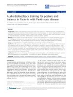
In this paper, we assume a streaming video service. The
abstracted parameters of this service include the source data
rate, the number of frames (or pictures) per second, size (in
terms of bytes), and maximum delay of each frame (or pic-
ture). Other important information for the optimizer is the
distortion-rate function (encoding distortion) and the so-
called loss distortion profile, which shows the distortion D
i
that is introduced in case the ith frame of the GOP is lost.
Figure 4 shows an example of the loss distortion profile of
lost frames for three different video sequences. This profile
is generated from a group of picture (GOP) with 15 frames,
starting with an independently decodable intraframe and fol-
lowed by 14 interframes. The interframes can only be suc-
cessfully decoded if all previous frames of the same GOP are
decoded error-free. The index in Figure 4 indicates the loss
of a particular frame, w hile the distor tion D
i
is quantified
by the mean-squared reconstruction error (MSE), which is
measured between the displayed and the transmission error-
free decoded video sequence. It is assumed that as part of
the error concealment strategy, all the following frames of
the GOP are not decodable and the most recent correctly de-
coded frame is displayed instead of the nondecoded frames
(copy the previous frame error concealment).
3.3. Cross-layer parameters
The abstracted parameter sets (
R and
A) from both the ap-
plication layer and the radio link layer form the input to
the cross-layer optimizer. Since any combination of the ab-
stracted parameter tuples from the two input sets is valid, it
Lai-U Choi et al. 5
is convenient to define the cross-layer parameter set
X =
R ×
A (7)
which combines the two input sets into one input set for
the optimizer. The set
X ={x
1
, x
2
, } consists of tuples
x
n
= (r
i
, a
j
). Note that the cardinality of the set
X grows
exponentially with the number of cross-layer parameters.
2
This means that the complexity of the cross-layer optimiza-
tion grows exponentially with the number of cross-layer pa-
rameters.
4. THE CROSS-LAYER OPTIMIZER
With the formalism introduced in Section 3, the operation of
the cross-layer optimizer Ω can now be described by
Ω :
X −→
Y ⊂
X. (8)
The optimizer gets as input the set
X of all possible ab-
stracted cross-layer parameter tuples and returns a true non-
empty subset
Y as its output. In the following, we assume
that
|
Y|=1, that is, the output of the optimizer is a single
tuple and
Y =
x
opt
∈
X. (9)
The decision or output
x
opt
of the cross-layer optimizer is
made with respect to a particular objective function
Γ :
X −→ R, (10)
where
R is the set of real numbers. Therefore, the output of
the optimizer can be expressed as
x
opt
= arg min
x∈
X
Γ
x
. (11)
Notice that because
X is a finite set, the optimization
(11) is performed by exhaustive search guaranteeing the
global optimal solution. The choice of a particular objective
function Γ depends on the goal of the system design, and the
output (or decision) of the optimizer might be different for
different objec tive functions. In the example application of
streaming video, one possible objective function in a single-
user scenario is the MSE between the displayed and the orig-
inal video sequence, that is, the sum of loss distortion MSE
L
and source distortion MSE
S
:
MSE
= MSE
S
+MSE
L
, (12)
where MSE
L
can be computed from the distortion profile by
MSE
L
=
15
i=1
D
i
P
i
, (13)
2
For instance, assume that all, say n, cross-layer parameters are quantized
to a fixed number, say q, of values. Then the cardinality of the set
X be-
comes q
n
, which shows exponential growth in the number of cross-layer
parameters.
where P
i
is the probability that the ith frame is the first frame
lost during transmission of this GOP and D
i
is the mean-
square er ror that is introduced by this l oss. Note that the
D
i
is taken from the measured distortion profile and is usu-
ally different for each GOP. Figure 4 shows an example dis-
tortion profile. The P
i
can be computed from the 2-state
Markov model as shown in Figure 3. For details, we refer to
[2, 10, 11].
For a multiuser situation, different extensions of the MSE
are possible. For example, the objective function can be the
sum of MSE of all the users. That is,
Γ(
x) =
K
k=1
MSE
k
(x), (14)
where MSE
k
(x) is the MSE of user k for the cross-layer pa-
rameter tuple
x ∈
X. This objective function will optimize
the average performance in terms of MSE among all users.
Another common definition of the objective function is
Γ(
x) = max
k∈{1,2, ,K }
MSE
k
(x) (15)
which ensures that the MSE is minimized with the constraint
that all users obtain the same MSE.
3
Yet another definition
Γ(x) =
K
k=1
MSE
k
(x) (16)
leads to a maximization of the average PSNR among all users.
5. DECISION DISTRIBUTION
Once the output
x
opt
=(r
opt
, a
opt
) of the cross-layer optimizer
is obtained, the decisions
r
opt
∈
R and a
opt
∈
A have to be
communicated back to the radio link layer and the applica-
tion layer, respectively. During this, the process of parameter
abstraction has to be reversed and the abstracted parameters
r
opt
and a
opt
have to be transformed back to the layer-specific
parameters r
opt
∈ R and a
opt
∈ A. This reverse transforma-
tion is given by
r
opt
∈
r |
r,r
opt
∈ G
,
a
opt
∈
a |
a, a
opt
∈ F
.
(17)
In case that
{r | (r, r
opt
) ∈ G} or {a | (a, a
opt
) ∈ F} has more
than one element, the choice of particular elements r
opt
and
a
opt
, respectively, can be made a t the corresponding layers in-
dividually.
6. SAMPLE NUMERICAL RESULTS
In this section, we provide sample simulation results to eval-
uate the performance of the proposed joint optimization. We
3
In practice, some or all of the cross-layer parameters may only take on
values from a finite set. The resulting gr anularity in general leads to not
allusershavingthesamequalityofserviceaswouldbethecaseifallpa-
rameters were continuously adjustable.
6 EURASIP Journal on Wireless Communications and Networking
Table 1: Multiuser scheduling: TDMA airtime assignment.
Case → 1234567
User 1 3/9 4/9 4/9 3/9 2/9 3/9 2/9
User 2 3/9 3/9 2/9 4/9 4/9 2/9 3/9
User 3 3/9 2/9 3/9 2/9 3/9 4/9 4/9
assume K = 3 users or clients (users 1, 2, and 3), each of
which requests a different video sequence. We assume that
users 1, 2, and 3 request the carphone (CP), foreman (FM),
and mother & daughter (MD) video test sequence, respec-
tively.
4
6.1. Objective function
We choose the peak-signal-to-noise ratio (PSNR) as our per-
formance measure. The PSNR is defined as
PSNR
= 10 · log
10
255
2
MSE
. (18)
The larger the PSNR is, the smaller the MSE is, which is com-
puted between the original video sequence and the recon-
structed sequence at the client or user. Therefore, the larger
the PSNR is, the better the performance is. As an example, we
use the objective function given in (15), which maximizes the
worst-case user’s performance. Therefore, the cross-layer op-
timizer chooses the parameter tuple that minimizes the max-
imum of MSE (or equivalently maximizes the minimum of
the PSNR) among the users. This leads to all users having the
same PSNR. However, the PSNR may nevertheless come out
different for each user because of granularity of the cross-
layer parameters (see footnote 3).
6.2. Physical layer and data link layer parameters
In the simulation, it is assumed that the data packet size s at
the radio link layer equals 432 bits, which is the same as the
specified packet size of the IEEE802.11a or HiperLAN2 stan-
dard [12]. The channel decorrelation time t is assumed to be
50 milliseconds for all the three users, which corresponds to a
pedestrian speed (about 2 Km/h at 5 GHz carrier frequency).
Since the transmission data rate d is influenced by the
modulation scheme, the channel coding, and the multiuser
scheduling, two different modulations (BPSK and QPSK)
are assumed. It is further assumed that there are 7 cases
4
We have chosen these particular video test sequences as they emphasize
different situations in a real-world video sequence. FM contains a scene
change with rather quick camera movement, MD has no camera move-
ment or scene change, while CP has a quickly moving background ac-
companied by medium foreground movement. These situations typically
occur in real-life video sequences and lead to rather different properties
of the encoded data streams, especially bit sizes of frames and sensitivity
to frame losses.
Table 2: Resulting transmission data rates in kbps for each user.
Case → 1234567Mod.
User 1 150 200 200 150 100 150 100
User 2 150 150 100 200 200 100 150
BPSK
User 3 150 100 150 100 150 200 200
Case → 8 9 10 11 12 13 14 Mod.
User 1 300 400 400 300 200 300 200
User 2 300 300 200 400 400 200 300 QPSK
User 3 300 200 300 200 300 400 400
of time arrangement in a time-division multiplexing-based
multiuser scheduling as shown in Tabl e 1 . A user’s transmis-
sion data rate is assumed to be equal to 100 kbps provided
that BPSK is used and 2/9 of the total transmission time is
assigned to it. Therefore, if QPSK is used and 4/9 of the total
transmission time is assigned, the user can have a transmis-
sion data rate as high as 400 kbps. Table 2 shows the resulting
transmission rate for each user as a function of the time ar-
rangement and modulation scheme (BPSK or QPSK).
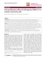
The transmission error rate on the other hand depends
on the transmission data rate, the average SNR, and the
error-correcting capability of the channel code. Usually, the
performance of a channel code is evaluated in terms of the
residual error rate (after channel decoding) for a given re-
ceive SNR. In our simulation, we assume a convolutional
code of code rate 1/2 and a data packet size of 432 bits. The
residual packet er ror ratio is shown in Figure 5(a) as a func-
tion of SNR [12]. However, in the wireless link, the receive
SNR is not constant, but is fluctuating around the mean
value (long-term SNR), which is due to fast fading caused
by user mobility. In this way, the receive SNR can be mod-
eled as a random variable with a certain probability distri-
bution, which is determined by the propagation property of
the physical channel (e.g., Rayleigh distribution, Rice distri-
bution). The residual packet error rate in a fading wireless
link is computed by averaging this packet error ratio (e.g.,
taken from Figure 5(a)) with the fading statistics. Assum-
ing Rayleigh fading, the resulting average packet error rate
is given in Figure 5(b) as a function of the average signal-to-
noise ratio
SNR. This resulting average packet error ratio is
used as the parameter e in (4) in our simulation.
User’s position-dependent path loss and shadowing com-
monly observed in wireless links are taken into account by
choosing the long-term average SNR randomly and indepen-
dently for each user uniformly within the range from 1 to 100
(0 dB to 20 dB).
In summary, the abstracted parameters, namely date rate
d
i
,packetsizes
i
, and Markov model parameters (p
i
, q
i
)for
each user and each of the 7 or 14 cases of modulation and
TDMA scheduling scheme (according to Table 1 or 2,resp.),
have to be communicated to the cross-layer optimizer.
Lai-U Choi et al. 7
10
3
10
2
10
1
10
0
Packet error rate
0 5 10 15
SNR (dB)
BPSK
QPSK
(a)
10
2
10
1
10
0
Average packet error rate
0 5 10 15 20
Average SNR (dB)
BPSK
QPSK
(b)
Figure 5: Example decoding error performances of a convolutional code with different modulations in an AWGN and a Rayleigh fading
channels: (a) packet error ratio after channel decoding as a function of the signal-to-noise ratio (SNR) in an AWGN channel [12]; (b) packet
error ratio after channel decoding as a function of the average signal-to-noise ratio
SNR in a Rayleigh fading channel.
6.3. Application layer parameters
At the application layer, it is assumed that the video is en-
coded using the H.264/AV C [13] video compression stan-
dard with 30 frames per second and 15 frames per GOP (i.e.,
0.5-second GOP duration). Two different values of the source
rate (100 kbps and 200 kbps) are considered. To this end, the
video has been pre-encoded at these two different target rates
and both versions are stored on the streaming server. We can
switch from one source stream to the other a t the beginning
of any GOP. In each GOP, the first frame is an I-frame and
the following 14 frames are P-frames. We use the measured
distortion profile of a particular lost frame and the encod-
ing distortion for the 3 requested videos. Figure 4 shows an
example of a distortion profile in terms of MSE for a GOP
at a source rate of 100 kbps. Also, note that since successful
decoding of P-frames depends on error-free reception of all
previous frames of the same GOP, losing the first frame of
a GOP leads to the largest distortion, while losing the last
frame of a GOP leads to the least distortion. Furthermore,
it is assumed that each video frame (or picture) is packe-
tized with maximum size of 432 bits and each packet only
contains data from one frame. The size of each frame is de-
termined during the H.264/AVC encoding. These values are
stored along with the bit stream and the distortion profile as
well as the value of the source distortion. Table 3 gives the
measured size (in terms of packets) for a GOP in the three
video sequences at a source rate of 100 kbps, w here I and Pn
(n
= 1, 2, , 14) denote the I-frame and the nth P-frame,
respectively. We can see that the size of an I-frame is much
larger than that of a P-frame and the size of a P-frame varies
from frame to frame. This is related to the contents of a video.
In summary, the abstracted parameters, namely the loss
distortion profile as shown in Figure 4 and the frame sizes as
shown Ta ble 3 for each user, have to be communicated to the
cross-layer optimizer.
6.4. Operating modes
An operation mode without ARQ (referred to as forward
mode) and an operation mode with ARQ (referred to as ARQ
mode) are investigated. We consider every GOP as a unit and
assume that each GOP has to be transmitted within the du-
ration of 0.5 second.
(i) Forward mode: we assume no acknowledgment from
the clients is available and the video frames of every GOP
for a particular client are repeatedly transmitted when the
transmission data rate is larger than the source data rate. For
instance, e very GOP is transmitted twice if the transmission
data rate is twice as large as the source data rate. If the trans-
mission data rate is 1.5 times the source data rate, a GOP is
transmitted once followed by retr ansmitting the I-frame, the
first P-frame, the second P-frame, and so forth, until the pe-
riod of 0.5 second for the GOP is expired.
(ii) ARQ mode: here we assume that instantaneous ac-
knowledgment of a transmitted packet is available from the
clients and the data packets of every GOP for a particular
client are retransmitted in the way that the data packets in a
GOP are received s uccessfully i n time o rder. That i s, before
transmitting a new packet, it is guaranteed that its previous
packets in the GOP are received correctly.
In the following, both modes of operation will be inves-
tigated.
6.5. Simulation results and discussion
Figures 6 and 7 provide simulation results of the following
three scenarios.
8 EURASIP Journal on Wireless Communications and Networking
Table 3: Measured sizes (in number of packets) of the encoded frames of a GOP for three different video sequences at 100 kbps.
Frame →
I P1P2P3P4P5P6P7P8P9P10P11P12P13P14
Sequence
↓
Carphone 43777658677 6 6455
Foreman 47567567655 6 5534
Mother&daughter50123334445 6 8 101214
0.1
0.2
0.3
0.4
0.5
0.6
0.7
0.8
0.9
1
Cumulative probability density function (CDF)
20 22 24 26 28 30 32 34 36 38
PSNR of the worst performing user (dB)
Forward mode w/oJO
Forward mode w/J O
ARQ mode w/oJ O
ARQ mode w/J O
(a)
0.1
0.2
0.3
0.4
0.5
0.6
0.7
0.8
0.9
1
Cumulative probability density function (CDF)
20 22 24 26 28 30 32 34 36 38
PSNR of the worst performing user (dB)
Forward mode w/oJO
Forward mode w/J O
ARQ mode w/oJ O
ARQ mode w/J O
(b)
Figure 6: Cumulative probability density function (CDF) of the PSNR of the worst performing user: (a) results for scenario 1, BPSK
modulation, and source rate of 100 kbps; (b) results for scenario 2, BPSK/QPSK modulation, and source rate of 100 kbps.
(1) Scenario 1: we restrict ourselves that only BPSK mod-
ulation is used at the radio link layer and only the source rate
with 100 kbps is available at the application layer. Therefore,
only one constant abstr acted parameter tuple (with 100 kbps
for all 3 users) is provided by the application layer (i.e.,
|
A|=1) in this scenario, while the radio link layer provides
7 abstracted parameter tuples (
|
R|=7), which result from
the 7 cases of time arrangement shown in Table 1. The cross-
layer optimizer selects one out of the 7 combinations of the
input parameter tuples (
|
X|=|
R|·|
A|=7) such that our
objective function given in (15) is optimized.
(2) Scenario 2: the same abstracted parameter tuple as in
scenario 1 is assumed at the application layer but the radio
link layer provides 14 abstracted parameter tuples, which re-
sult from the 7 cases of time arrangement with BPSK and
another 7 cases of time arrangement with QPSK.
(3) Scenario 3: it is assumed that the two different source
rates of 100 kbps and 200 kbps for each of the 3 users are pro-
vided by the application layer. This results in
|
A|=2
3
= 8
abstracted par ameter tuples from the application layer. The
same 14 abstracted parameter tuples as in scenario 2 are pro-
vided by the radio link layer.
The distortion MSE given in (12)isarandomvari-
able controlled by the two factors, namely fast fading and
user’s position-dependent path loss and shadowing. In gen-
eral, fast fading takes place on a much smal l er time scale
than the path loss and shadowing. In this paper, we eval-
uate the MSE averaged over fast fading by taking the ex-
pected value of the MSE with respect to the fast fading
for a particular position of the users or equivalently for a
particular long-term SNR. Based on this value, the cross-
layer optimizer makes its decision. We also look at its sta-
tistical properties for an ensemble of user positions. There-
fore, the cumulative probability density function (CDF) of
this average MSE is chosen to show the performance of
both modes (for w ard mode and ARQ mode). The perfor-
mance of the worst performing user in the system with the
proposed joint optimization (w/JO) is compared with that
in a system without joint optimization (w/oJ O). A system
without joint optimization is assumed to assign the same
amount of transmission time to all the users (i.e., Case 1 in
Table 1) and use BPSK modulation, while the source data
rate is fixed to 100 kbps. It can be seen from Figure 6(a)
that the PSNR of the worst performing user improves sig-
nificantly in the system w/JO. For instance, there is about
1
− 40% = 60% chance that the PSNR of the worst perform-
ing user is larger than 30 dB in the system w/JO in forward
mode, which improves to 2 dB when compared to the system
w/oJ O.
Lai-U Choi et al. 9
0.1
0.2
0.3
0.4
0.5
0.6
0.7
0.8
0.9
1
Cumulative probability density function (CDF)
20 22 24 26 28 30 32 34 36 38
PSNR of the worst performing user (dB)
Forward mode w/oJO
Forward mode w/J O
ARQ mode w/oJ O
ARQ mode w/J O
(a)
0.1
0.2
0.3
0.4
0.5
0.6
0.7
0.8
0.9
1
Cumulative probability density function (CDF)
02468
Δ PSNR (dB)
Scenario 1
Scenario 2
Scenario 3
(b)
0.1
0.2
0.3
0.4
0.5
0.6
0.7
0.8
0.9
1
Cumulative probability density function (CDF)
02468
Δ PSNR (dB)
Scenario 1
Scenario 2
Scenario 3
(c)
Figure 7: (a) Cumulative probability density function (CDF) of the PSNR of the worst performing user for scenario 3, B PSK/QPSK mod-
ulation and source rate of 100 kbps/200 kbps; (b) performance improvement for the three scenarios in forward mode; (c) performance
improvement in ARQ mode.
A similar trend of improvement can be observed in
Figure 6(b) and Figure 7(a) for scenarios 2 and 3, respec-
tively. The performance improves when more abstracted pa-
rameter tuples are provided because more degrees of free-
dom can be obtained. This can be observed in Figure 7(b)
and Figure 7(c) more clearly, where the performance im-
provement of the three investigated scenarios is shown. Here,
ΔPSNR is defined as the difference between the PSNR of
the worst performing user in the system w/JO and that in
the system w/oJ O. A close observation of Figure 7(b) reveals
that the amount of performance improvement of scenario
2 is much larger than that of scenario 1 in forward mode,
while the amount of performance improvement of scenario
3 is only slightly larger than that of scenario 2. This indicates
that the choice of higher transmission data rate (by using
QPSK) provided by the radio link layer is favorable in for-
ward mode, and the optimizer chooses it frequently. In con-
trast, the choice of higher source rate (200 kbps) provided by
the application layer is not so favorable in this mode and the
optimizer seldom chooses it. On the other hand, this choice
of a higher source rate is favorable in ARQ mode, which can
be seen from the graph in Figure 7(b), where the amount of
performance improvement of scenario 3 is fairly larger than
that of scenario 2. Therefore, choosing a suitable set of ab-
stracted parameters tuples is important in order to obtain
large performance improvements while optimizing at low
complexity.
7. CONCLUSION AND OUTLOOK
We have exploited the interlayer coupling of a cross-layer
design concept and proposed an architecture for the joint
optimization with three principle concepts, namely param-
eter abstraction, cross-layer optimization, and decision dis-
tribution. Although we have focused on the application layer
and radio link layer in a wireless system with a video stream-
ing service, this architecture can be easily generalized for dif-
ferent layers and different services. Our study reveals that
this proposed architecture can provide a potential way to
improve the performance and therefore help dealing with
the future challenges in wireless multimedia communica-
tion. Even when considering a small number of degrees of
freedom of the application layer and the radio link layer, we
obtain significant improvements in user-perceived quality of
our streaming video application by joint optimization. Note
that we only consider the wireless hop in this study. Further
sophisticated research might be required in order to exploit
this cross-layer design concept more completely. This work
has been partially presented at ICIP’04 [14].
ACKNOWLEDGMENTS
The authors would like to thank the DoCoMo Communica-
tion Laboratories Europe GmbH, Munich, and the Alexan-
der von Humboldt Foundation (AvH) for kindly supporting
this research and thank Dr. Michel T. Ivrla
ˇ
cforveryvaluable
input and discussion.
REFERENCES
[1] V. Kawadia and P. R. Kumar, “A cautionary perspective on
cross-layer design,” IEEE Wireless Communications, vol. 12,
no. 1, pp. 3–11, 2005.
[2] L. Choi, M. T. Ivrla
ˇ
c, E. Steinbach, and J. A. Nossek, “Bottom-
up approach to cross-layer design for vi deo transmission over
10 EURASIP Journal on Wireless Communications and Networking
wireless channels,” in Proceedings of the IEEE Vehicular Tech-
nology Conference (VTC ’05), pp. 3019–3023, Stockholm, Swe-
den, May 2005.
[3]M.T.Ivrla
ˇ
c, Wireless MIMO Systems - Models, Performance,
Optimization, Shaker, Aachen, Germany, 2005.
[4] J. Brehmer and W. Utschick, “Modular cross-layer optimiza-
tion based on layer descriptions,” in Proceedings of the Wire-
less Personal Multimedia Communications Symposium (WPMC
’05), Aalborg, Denmark, September 2005.
[5] M. Van Der Schaar and S. Shankar N, “Cross-layer wire-
less multimedia transmission: challenges, principles, and new
paradigms,” IEEE Wireless Communications,vol.12,no.4,pp.
50–58, 2005.
[6] S. Khan, Y. Peng, E. Steinbach, M. Sgroi, and W. Kellerer, “Ap-
plication-driven cross-layer optimization for video stream-
ing over wireless networks,” IEEE Communications Magazine,
vol. 44, no. 1, pp. 122–130, 2006.
[7] M.T.Ivrla
ˇ
c and F. Antreich, “Cross OSI layer optimization -
an equivalence class approach,” Tech. Rep. TUM-LNS-TR-03-
09, Institute for Circuit Theory and Signal Processing, Munich
University of Technology, Munich, Germany, May 2003.
[8] M. T. Ivrla
ˇ
c and J. A. Nossek, “Cross layer design - an equiva-
lence class approach,” in Proceedings of the International Sym-
posium on Signals, Systems, and Electronics (ISSSE ’04), Linz,
Austria, August 2004.
[9] M. T. Ivrla
ˇ
c, “Parameter selection for the Gilbert-Elliott
model,” Tech. Rep. TUM-LNS-TR-03-05, Institute for Circuit
Theory and Signal Processing, Munich University of Technol-
ogy, Munich, Germany, May 2003.
[10] L.U.Choi,M.T.Ivrla
ˇ
c, E. Steinbach, and J. A. Nossek, “Anal-
ysis of distortion due to packet loss in streaming video trans-
mission over wireless communication links,” in Proceedings of
the International Conference on Image Processing (ICIP ’05),
vol. 1, pp. 189–192, Genova, Italy, September 2005.
[11] Y. Peng, S. Khan, E. Steinbach, M. Sgroi, and W. Kellerer,
“Adaptive resource allocation and frame scheduling for wire-
less multi-user video streaming,” in Proceedings of the Inter-
national Conference on Image Processing (ICIP ’05), vol. 3, pp.
708–711, Genova, Italy, September 2005.
[12] J. Khun-Jush, G. Malmgren, P. Schramm, and J. Torsner,
“HIPERLAN type 2 for broadband wireless communication,”
Ericsson Review, vol. 77, no. 2, pp. 108–119, 2000.
[13] T. Wiegand, G. J. Sullivan, G. Bjontegaard, and A. Luthra,
“Overv iew of the H.264/AVC video coding standard,” IEEE
Transactions on Circuits and Systems for Video Technology,
vol. 13, no. 7, pp. 560–576, 2003.
[14] L. Choi, W. Kellerer, and E. Steinbach, “Cross layer optimiza-
tion for wireless multi-user video streaming,” in Proceedings
of the International Conference on Image Processing (ICIP ’04),
vol. 3, pp. 2047–2050, Singapore, Republic of Singapore, Oc-
tober 2004.
Lai-U Choi received the B.Eng. degree from
the University of Macau, Macau, in 1998.
She was educated in the Hong Kong Univer-
sity of Science and Technology (HKUST),
Hong Kong, for the M .Phil. and the Ph.D.
study from 1998 to 2003, all in electrical and
electronic engineering. During this period,
she has also been a Research Assistant con-
ducting research on MIMO signal process-
ing for downlink wireless communications
at HKUST. After she obtained her Ph.D. degree in 2003, she has
joined the Department of Electrical Engineering and Information
Technology at Munich University of Technology, Germany. Her
current research interests include the areas of smart/MIMO an-
tenna systems, multiuser communications, signal processing for
wireless communications, multimedia communications, commu-
nication networks, resource allocation, and coding theory.
Wolfgang Kellerer is a Senior Manager
at NTT DoCoMo’s European Research
Laboratories, Munich, Germany, heading
the Ubiquitous Services Platform Research
Unit. His current research interests are in
theareaofmobilesystemsfocusingonmo-
bile service platforms, peer-to-peer, sensor
networks, and cross-layer design. In 2004
and 2005, he has served as the elected Vice
Chairman of the Working Group 2 (Service
Architecture) of the Wireless World Research Forum (WWRF). He
is a Member of the editorial board of Elsevier’s International Jour-
nal of Computer and Telecommunications Networking (COM-
NET) and serves as a Guest Editor for the IEEE Communications
Magazine in 2006. He has published over 60 papers in respective
journals, conferences, and workshops in the area of service plat-
forms and mobile networking and he filed more than 20 patents.
Before he joined DoCoMo Euro-Labs, he has been a Member of the
research and teaching staff at the Institute of Communication Net-
works at Munich University of Technology. In 2001, he was a Visit-
ing Researcher at the Information Systems Laboratory of Stanford
University. He received a Dipl Ing. degree (M.S.) and a Dr Ing.
(Ph.D.) degree in electrical engineering and information technol-
ogy from Munich University of Technology, Germany, in Decem-
ber 1995 and in January 2002, respectively. He is a Member of IEEE
ComSoc and the German VDE/ITG.
Eckehard Steinbach studied electrical en-
gineering at the University of Karlsruhe
(Germany), the University of Essex (Great
Britain), and Ecole Sup
´
erieme d’ Ing
´
enieurs
en
´
Electronique et
´
Electrotechnique (ES-
IEE) in Paris. From 1994 to 2000, he was a
Member of the research staff of the Image
Communication Group at the University of
Erlangen-Nuremberg (Germany), where he
received the Engineering Doctorate in 1999.
From February 2000 to December 2001, he was a postdoctoral fel-
low with the Information Systems Laboratory of Stanford Univer-
sity. In February 2002, he joined the Department of Electrical En-
gineering and Information Technology of Munich University of
Technology (Germany), where he is currently an Associate Profes-
sor for Media Technology. His current research interests are in the
area of networked and interactive multimedia systems. He served as
a Conference Cochair of “SPIE Visual Communications and Image
Processing (VCIP)” in San Jose, Calif, in 2001, and “Vision, Model-
ing and Visualization 2003 (VMV)” in Munich, in November 2003.
He has been a Guest Editor of the Special Issue on Multimedia over
IP and Wireless Networks of the EURASIP Journal on Applied Sig-
nal Processing. He currently is a Guest Editor of the EURASIP Jour-
nal on Applied Signal Processing, Special Issue on Advanced Video
Technologies and Applications for H.264/AVC and Beyond. From
2006 to 2007, he serves as an Associate Editor for the IEEE Trans-
actions on Circuits and Systems for Video Technology (CSVT).