Báo cáo hóa học: " Multiple-Channel Security Architecture and Its Implementation over SSL" pptx
Bạn đang xem bản rút gọn của tài liệu. Xem và tải ngay bản đầy đủ của tài liệu tại đây (1.14 MB, 14 trang )
Hindawi Publishing Corporation
EURASIP Journal on Wireless Communications and Networking
Volume 2006, Article ID 85495, Pages 1–14
DOI 10.1155/WCN/2006/85495
Multiple-Channel Securit y Architecture
and Its Implementation over SSL
Yong Song, Konstantin Beznosov, and Victor C. M. Leung
Department of Electrical and Computer Engineering, Faculty of Applied Sciences, University of British Columbia, 2356 Main Mall,
Vancouver, BC, Canada V6T 1Z4
Received 2 October 2005; Revised 18 April 2006; Accepted 21 April 2006
This paper presents multiple-channel SSL (MC-SSL), an architecture and protocol for protecting client-server communications.
In contrast to SSL, which provides a single end-to-end secure channel, MC-SSL enables applications to employ multiple channels,
each with its ow n cipher suite and data-flow direction. Our approach also allows for several partially trusted application proxies.
The main advantages of MC-SSL over SSL are (a) support for end-to-end security in the presence of partially trusted proxies, and
(b) selective data protection for achieving computational efficiency important to resource-constrained clients and heavily loaded
servers.
Copyright © 2006 Yong Song et al. This is an open access article distributed under the Creative Commons Attribution License,
which permits unrestr icted use, distribution, and reproduction in any medium, provided the original work is properly
cited.
1. INTRODUCTION
While the Internet is advancing from wireline to wireless
networks, a growing number of handheld devices—such
as cellular phones, PDAs, and palmtops—can access In-
ternet applications, for example, Web, e-mail, multimedia,
and so forth. Securing client-server communication between
resource-constrained handheld devices and heavily loaded
Internet servers has been a challenge. A handheld device
has many more constraints than an ordinary computer in
terms of power, processor, memory, display, and other re-
sources. The access channels of handheld devices range from
2G/2.5 G/3 G cellular networks, wireless LAN, and bluetooth
to dial-up and LAN. Some of these are slow, unreliable, and
expensive. A handheld device is still resource-constrained,
even though it uses a wireline interface such as LAN for com-
munication. Besides, the operating system and software of
a handheld device often have fewer functions than those of
an ordinary computer. However, many Internet applications
and protocols are designed mainly for ordinary computers.
For these reasons, handheld devices pose challenges to secure
client-server communications.
This paper presents a new security architecture and
protocol for securing client-server communications, named
multiple-channel SSL (MC-SSL). Although this work fo-
cuses on wireless handheld or mobile devices, MC-SSL is
designed as a general security protocol for a wide range
of client-server applications. It supports multiple channels
between a client and a server. Each channel can be either
a direct or a proxy channel with one or more intermedi-
ary proxies; moreover, each channel can have its ow n ci-
pher suite and data-flow direction. During an application
session, a client and a server establish channels according
to their specific needs for data protection and selectively
use the channels to communicate directly or through prox-
ies.
Compared to secure socket layer/transport layer secu-
rity (SSL/TLS, or SSL for short) [1], the de facto security
protocol for the Web and MC-SSL enjoys four main advan-
tages. First, it enhances end-to-end security in the presence of
partial ly trusted application proxies. Second, with MC-SSL’s
support for multiple cipher suites, both client and server can
optimize computational and communication costs while ex-
changing data with different protection requirements. Third,
it supports channel-direction restriction, which prevents a
response channel from being turned into a request channel,
and vice versa, by a malicious proxy. Finally, MC-SSL sup-
ports channel negotiation based on security policies, device
capabilities, and security requirements for the data sent over
the channels. Consequently, MC-SSL can better fulfill the di-
verse requirements of d ifferent clients, servers, applications,
and users. MC-SSL design extends SSL by introducing new
features that enable the SSL protocol and implementations
to be reused.
2 EURASIP Journal on Wireless Communications and Networking
CS
SSL
C
SSL
P
1
SSL
P
n
SSL
S
Figure 1: The point-to-point and proxy-chain models of SSL.
The rest of this paper is organized as follows: Section 2
describes the problems and limitations of SSL. Section 3
outlines related work. Section 4 presents the MC-SSL ar-
chitecture. Section 5 discusses the MC-SSL protocol design.
Section 6 demonstrates implementation. Section 7 draws
conclusions.
2. PROBLEM MOTIVATION
Although SSL is the de facto application security protocol
for the Internet, it has several limitations. First, SSL cannot
help applications protect information from partially trusted
application proxies, which leads to the necessity of uncon-
ditionally trusting proxies. Second, due to the high cost of
changing a cipher suite once an SSL connection is estab-
lished, all data, independent of differences in security re-
quirements, is protected unvaryingly, resulting in either over-
protection or underprotection. Third, SSL does not contain
sufficient negotiation capabilities to support selective protec-
tion of data and the negotiation of proxy use. After a brief
description of SSL, this section discusses these limitations in
detail.
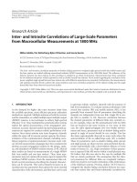
Figure 1 illustrates a simplified communication model of
SSL. The upper part of the figure shows a point-to-point se-
cure channel over a TCP connection between client C and
server S. Channel security is achieved by making use of a ci-
pher suite, which defines a key exchange algorithm, a bulk
encryption algorithm, and a hash algorithm. For example,
TLS
RSA WITH IDEA CBC SHA cipher suite uses RSA a l-
gorithm [2, 3] to perform authentication and key exchange,
IDEA (international data encryp tion algorithm) [2, 3]to
perform encryption and decryption, and SHA-1 (secure hash
algorithm) [2, 3] to generate MAC (message authentication
code) [1]. MAC protects data integrity. CBC (cipher block
chaining) [2, 3] is a mode of operation for block ciphers
such as IDEA. Please refer to RFC 2246 [1] for the details
of SSL/TLS. The following subsections use the above model
to explain the limitations of SSL addressed by MC-SSL.
2.1. Problem with trusted proxies
Application proxies pose security risks. Due to their con-
straints, many handheld devices require application proxies
to perform content transformation or scanning. For exam-
ple, most Web sites do not provide Web pages designed for
handheld devices, and so the Web browser of a handheld de-
vice is likely unable to display a Web page not transformed by
WAP
device
WAE
WSP
WTP
WTLS
WDP
Bearer
WAP
gateway
WSP
WTP
WTLS
WDP
Bearer
HTTP
SSL
TCP
IP
Web
server
WAE
HTTP
SSL
TCP
IP
Figure 2: WAP 1.X gateway architecture (adapted from [4]).
an intermediary proxy. Even desktop computers sometimes
use n application proxies, for example, an application fire-
wall for virus scanning/filtering.
The need for an application proxy is not in itself a lim-
itation, but for sensitive information in transit, it becomes
difficult to achieve end-to-end security between a client and
a server. Although SSL is the de facto security protocol on the
Web, it cannot prevent information leakage, tampering, and
impersonation by an application proxy.
As illustrated in the lower part of Figure 1, SSL enables
point-to-point protection of the communication between
any two directly connected entities through unconditionally
trusted proxies. SSL is vulnerable to malicious proxies, as any
proxy in the chain can read and/or modify data. In other
words, a proxy can compromise the end-to-end security be-
tween C and S. The use of proxies with SSL implicitly re-
quires that at least one endpoint (C or S) has unconditional
trust in the proxies used between the endpoints. This require-
ment can be satisfied only if the proxies are administered by
the organization or individual that also administers the trust-
ing endpoint. Note that if a proxy works below the applica-
tion layer, for example, at the transport layer, then C and S
can still establish an end-to-end SSL session. For this reason,
SOCKS proxy mechanism and network address translation
(NAT) do not affect the normal operation of SSL. In this pa-
per, the term “proxy” designates a proxy or gateway at the
application layer.
A typical example of using proxies with SSL is the WAP
1.X gateway architecture shown in Figure 2. The communi-
cation between a WAP device and a WAP gateway is pro-
tected by WTLS, a variant of the SSL protocol for wireless
communications. Clearly, the WAP 1.X gateway shown in
Figure 2 is an application proxy because it performs content
transformation, recoding, and/or compression for the con-
tent carried by HTTP or WSP/WTP protocols. Since this ar-
chitecture is a proxy architecture that employs SSL, it has the
same limitation as the SSL proxy chains. The architecture is
secure only when the gateway is trustworthy, for instance,
when the Web server owner provides the gateway.
2.2. Limitation of cipher suites and channel direction
The second limitation of SSL stems from the redundant cryp-
tographic protection in client-server SSL communications.
Yong Song et al. 3
Cryptographic algorithms such as RSA [2], 3DES [2], and
AES are computationally expensive, especially for a hand-
held device or a heavily loaded server. If a processor is fully
dedicated to security processing, the processing requirements
for 3DES, AES, SHA (secure hash algorithm) [2], and MD5
(message digest 5) [2] at 10 Mbps are 535.9, 206.3, 115.4,
and 33.1 MIPS (millions of instructions per second), respec-
tively [5]. In comparison, a handset processor such as Intel’s
StrongARM processor SA-1110 can deliver around 235 MIPS
at 206 MHz [5]. A common goal of designing hardware and
software for wireless handheld devices is to reduce battery
power use and processor time as much as possible.
During an SSL session, only one cipher suite can be used
at any time. Although SSL can change the cipher suite with a
full handshake, doing so is inefficient because a full hand-
shake entails communicationally expensive message inter-
action and computationally expensive public key certificate
verification. Besides, SSL does not support restriction on
channel directions, such as a simplex channel. SSL provides
only a duplex channel, in which the cipher suites for both
directions are identical. When requests and responses need
different types of data protection, for example, an applica-
tion cannot flexibly employ different cipher suites. In fact,
few applications can change their cipher suites during an SSL
session. This limitation is partially due to the high cost of
changing cipher suites. As a result, data protection is coarse-
grained.
There are several types of redundant protection. First,
not all information is confidential, but it is still encrypted
with confidential information using the same cipher in an
SSL session. For example, a Web page for online banking
contains confidential information, including account num-
bers and balances; however, other parts of the Web page,
including HTML tags, JavaScript/Java code, images, adver-
tisements, are not confidential. For example, after examining
the HTML pages sent to Web browsers by one of the online-
banking systems, we have determined that only around 4%
of the data requires both integrity and confidentialit y protec-
tion, with the rest needing just integrity or no protection at
all [6]. For that latter data, expensive encr yption operations
are unnecessary, and HMAC (keyed-hash message authenti-
cation code) based on MD5 or S HA-1 can be adequate for
providing data integrity. Our experiments with Java secure
socket extension (JSSE) show that CPU savings could be up
to 37% in those cases when 96% of data is nonconfidential
and can be sent over an integrity-only channel [6]. This value
could tra nslate to a battery-life saving, but the relationship is
different for each platform and user style.
Second, some information is already secured at the ap-
plication layer. For example, some software, e-mail messages,
and documents are already digitally signed or encrypted with
digital certificates, PGP, or XML security. Extra protection
by SSL is likely redundant in those cases. Third, many ap-
plications require authentication but do not need data pro-
tection after the login stage. In fact, different users and ser-
vice providers have different security requirements. In sum-
mary, there is a need to support selective protection. Although
choosing or switching between HTTP and HTTPS URL links
can provide selective protection to some degree, it works only
for Web applications at coarse granularity [7]. Applications
require selective protection at finer granularity.
2.3. Weak negotiation capabilities
The third problem with SSL is the lack of sufficient infor-
mation provided during the negotiation phase. To decide
whether or not and how to use proxies, multiple cipher
suites, and simplex channels, C and S must exchange suffi-
cient information to make the right decisions that optimize
the combination of different channels. Generally, C needs to
inform S of its device capabilities and security policy. For
example, C may define whether proxies are allowed to pro-
cess data with sensitivity below a certain level, what cipher
suites are strong enough to protect data with a certain level
of sensitiv ity, and so on. Lack of negotiation support is SSL’s
third limitation. Moreover, the core of these limitations is
that the negotiation and decision process of SSL does not take
the security policies, device capabilities, and other important
factors into account. These functional limitations constitute
a mismatch between SSL and the diverse requirements of
client-server applications. When handheld devices and m o-
bile applications become more popular, this gap will likely
become more apparent.
3. RELATED WORK
There are other methods for addressing the limitations de-
scribed in Section 2, namely, changing cipher suites in SSL
each time a different level of data protection is required, es-
tablishing several independent SSL connections, using SSL
extension for a cleartext channel, employing ITLS, selectively
protecting data using XML security technologies, and re-
ducing associated costs by accelerating cryptographic oper-
ations. This section explains why none of these methods ad-
dresses the problems as adequately as MC-SSL.
There are several reasons why frequently changing cipher
suites in SSL is unsuitable. First, an SSL client and SSL server
do not have enough information—such as security policies
and device capabilities—to decide if a new cipher suite is ap-
propriate. Second, a full SSL handshake , including authen-
tication and key exchange, is very inefficient for changing a
cipher suite. Third, messages traveling in opposite directions
often need different levels of protection, but it is very ineffi-
cient to change the cipher suite for each request or response
by doing a full handshake. MC-SSL does not h ave these draw-
backs.
A simple approach for improving the end-to-end secu-
rity of the SSL proxy chain model is to have two simulta-
neous connections between C and S: a direct SSL connec-
tion and an SSL proxy chain. With both connections inde-
pendent of each other, sensitive data would be transmitted
only through the direct connection. This intuitive solution
adopted by some applications (e.g., [8]) suffers from the need
of the intermediate proxy P to i mpersonate C while authen-
ticating to S. Generally, P cannot bind a connection with S to
that between C and S using its own identity, even if C uses a
4 EURASIP Journal on Wireless Communications and Networking
public key certificate for authentication. In contrast, proxies
in MC-SSL are negotiated through the direct—also referred
to in this paper as the “end-to-end”—channel before C starts
to set up a proxy channel with S.Moreover,P can then use
the session ID received from C for authenticating with S.In
brief, a proxy in MC-SSL is authenticated as a proxy, not as a
client.
Portmann and Seneviratne [7] propose a simple exten-
sion to SSL to obtain an extra cleartext channel. Their new
record-type cleartext application data (CAD) adds a clear-
text channel to an SSL connection. To some degree, this
channel resembles a cleartext end-to-end channel in MC-
SSL; however, their channel is permanent and independent,
which makes it insecure with proxies even if no sensitive
data goes through it, because undetected data can be in-
jected into the channel by any proxy. Without MAC or a
digital signature, a cleartext channel cannot prevent infor-
mation tampering or injection, and nonsensitive data could
be displayed side by side with sensitive data. For this rea-
son, an obvious drawback of the CAD-based approach is
that it is always present, even if it is considered both un-
necessary and insecure for some applications. Moreover,
a CAD-based approach can create only cleartext channels.
In comparison, MC-SSL can provide a variety of chan-
nels, including proxy channels and end-to-end channels
created with various cipher suites. Moreover, every chan-
nel is securely negotiated among client, server, and prox-
ies.
Kwon et al. [9] propose integrated transport layer se-
curity (ITLS) to avoid information leakage at a WAP gate-
way. The goal of ITLS is to prohibit the WAP gateway from
having access to the plaintext of messages exchanged be-
tween C and S. To achieve this, C encrypts a message twice
for S and P using KC
S
and KC
P
, in that order. P decrypts
the cipher text using KC
P
and then sends it to S,which
decrypts the data with KC
S
. In reverse, S encrypts a mes-
sage using KC
S
and sends it to P. P encrypts it again us-
ing KC
P
and then forwards it to C. C decrypts it twice
using KC
P
and KC
S
to get the message. With ITLS, the
gateway cannot perform content transformation and scan-
ning, a limitation that MC-SSL does not have. In addi-
tion, ITLS requires a handheld device to perform encryp-
tion/decryption twice as often as SSL, further increasing the
CPU time.
XML-based solutions to data protection such as XML
security [10, 11] and Web services security (WS-security)
[12–15] have the potential to solve the problems addressed
by MC-SSL. XML-based solutions are different from MC-
SSL in several aspects. First, they are not self-contained se-
curity protocols for client-server applications. That is, with
just XML-based encryption/signing, mutual authentication
and key exchange among client, server, and proxies can-
not be per formed individually; one has to rely on the secu-
rity infrastructure. Second, XML-based solutions do not de-
fine mechanisms for negotiating different types of channels,
while MC-SSL has such mechanisms. Third, XML-based so-
lutions generally belong to the application layer. As such, they
requirebothclientandservertosupportXMLandXML
security, which is not optimal for those applications that ex-
change mostly binary data.
MC-SSL defines a protocol between t ransport and appli-
cation layers, and works for a variety of applications, includ-
ing Web services. Besides the above differences, MC-SSL has
some advantages over XML-based solutions. First, MC-SSL
is more efficient than XML-based solutions: the latter com-
monly require binary data to be transformed into text using
base 64 encoding, which could significantly increase network
traffic and CPU consumption for certain applications. Sec-
ond, MC-SSL is an extension of SSL, and SSL is the de facto
application security protocol with its implementations be-
coming commodities in most modern distributed environ-
ments. Therefore, we expect the cost of the transition from
SSL to MC-SSL to be much smaller than to XML secur ity.
SSL splitting [16] is a technique for guaranteeing the in-
tegrity of data served from proxies without requiring changes
to Web clients. This technique reduces the bandwidth load
on the server, while allowing an unmodified Web browser to
verify that the data served from proxies is endorsed by the
originating server. With SSL splitting, the Web server sends
the SSL record authenticators, and the proxy merges them
with a stream of message payloads retrieved from the proxy’s
cache. The merged data stream that the proxy sends to the
client is indistinguishable from a normal SSL connection be-
tween the client and the server. SSL splitting is geared towards
secure public file downloads, in which the concern is data in-
tegrity rather than confidentiality.
SSL splitting is similar to MC-SSL in that it is able to pro-
vide data integrity in the presence of a partially trusted proxy.
In addition, MC-SSL can provide confidentiality by routing
sensitive data via a direct channel, and less or nonsensitive
data through a proxy channel. An MC-SSL proxy channel can
have several proxies, whereas SSL splitting supports only one.
Even though SSL splitting does not require modifications to
the client as MC-SSL does, b oth approaches make changes to
the protocol between the ser ver and the proxy.
4. MC-SSL ARCHITECTURE
MC-SSL improves end-to-end security in the presence of ap-
plication proxies by establishing proxy channels, and reduces
redundant cryptographic protection by supporting channels
with different cipher suites. MC-SSL can provide an applica-
tion session with multiple-virtual channels. The negotiation
of channels is based on security policies, device capabilities,
and the security attributes of application data of both client
and server.
In MC-SSL, a cipher suite consists of only two elements:
a cipher for data encry ption and decryption, and a hash al-
gorithm for MAC, and hence can be denoted as follows:
cipher and key size, hash algorithm for MAC
. (1)
As shown in Figure 3, a connection in MC-SSL can have
multiple cipher suites. We characterize a point-to-point con-
nection as follows:
{endpoint 1, endpoint 2, key exchange al-
gorithm,
{cipher suite 1, cipher suite 2, }}, where each ci-
pher suite for ms a channel. Every MC-SSL connection must
first have a strong cipher suite (e.g., a 128-bit cipher plus
Yong Song et al. 5
AB
4
3
1
2
Figure 3: Multiple cipher suites inside a connection.
C
S
P
1
P
n
Figure 4: Proxy channel model of MC-SSL.
SHA-1) to form the primary channel, which provides the
backbone for setting up and controlling other channels in
the same connection. A primary channel is the first chan-
nel in an MC-SSL connection, and it can be set up with the
unchanged SSL protocol. Other channels in an MC-SSL con-
nection are referred to as secondary channels. They are new
channels added to an SSL connection to support multiple ci-
pher suites. The sample connection in Figure 3 can be char-
acterized as
{A, B,RSA,{CS1, CS2, CS3, CS4}}, where RSA is
the key exchange algorithm, and CS1 through CS4 are cipher
suites for channels 1 to 4, respectively. Among them, channel
1 is the primary channel.
The proxy channel model of MC-SSL is illustrated in
Figure 4, in which the point-to-point connections collec-
tively form an arc. C-S is termed an end-to-end channel, and
C-P
1
-···-P
n
-S is called a proxy channel. In this model, C-P
1
-
···-P
n
-S is a channel that relies on the C-S channel to per-
form channel negotiation and to transport application data.
An end-to-end channel must exist before the proxy channel
negotiation is started. Through an end-to-end channel, C
and S exchange messages about what proxies they want and
the other parameters of the proxy channel. After that, C and
S interact with proxies to set up the proxy channel. The C-
S channel is also used to control data transmission through
the proxy channel. C or S can deliberately choose one of the
two channels to transport data according to the data’s secu-
rity requirements. For example, sensitive information, such
as passwords and credit card numbers, can be transported
using the end-to-end channel. An MC-SSL session can have
zero or more proxy channels. Each of them and the corre-
sponding end-to-end channel reflect the proxy architecture
shown in Figure 4.
Combining the proxy-channel architecture and multiple
cipher suites leads to the multiple-channel architecture il lus-
trated in Figure 5, with distinct SSL connections shown as
cylinders. In MC-SSL, a channel is a protected communica-
tion “pipe,” with a certain cipher suite and a number of appli-
cation proxies. If there is no application proxy in the channel,
then it is an end-to-end channel; if there is no cipher suite
for the channel (the cipher suite is null), then it is a plaintex t
CS
P
1
P
n
5
4
5
4
2
1
3
5
4
Figure 5: Multiple-channel architecture of MC-SSL.
channel. Additionally, a channel can be duplex, simplex,or
inactive. The restriction on channel direction applies only to
application data messages, not to channel control messages.
An MC-SSL channel can be characterized as follows:
channel
≡
ID, E
1
, E
2
,CS,
P
1
, P
2
, , P
n
, D
. (2)
ID is a channel’s identity number. E
1
and E
2
are either
DNS names or the IP addresses of the corresponding end-
points. Cipher suite, CS, is defined by expression (1). A proxy
(P
i
) is identified by its DNS name or IP address. A chan-
nel can have zero or more proxies. Direction, D, indicates
whether a channel is a duplex, an inactive, or a simplex one
pointing to one of the two endpoints. An inactive chan-
nel cannot be used to transmit application data, but it can
be used for transmitting channel control messages if it is
a primary channel. Channel control messages can only go
through primary channels.
We illustrate the MC-SSL architecture with Figure 5.The
sample MC-SSL session has five channels. Among them,
channels 1 and 4 are primary channels, and the others are
secondary channels. Furthermore, channel 1 is the primary
end-to-end channel, and channel 4 is a primary proxy chan-
nel; channels 2 and 3 are secondary end-to-end channels, and
channel 5 is a secondary proxy channel. Note that an MC-SSL
session can have multiple-primary channels. The number of
primary channels in an MC-SSL session is equal to the num-
ber of SSL connections with S as an endpoint. Channels 2, 3,
and 4 are negotiated through channel 1, and channel 5 is ne-
gotiated through channel 4. Additionally, only channel 1 is a
duplex channel for application data; others are simplex chan-
nels from S to C. In this application scenario, C uses channel
1 to send encrypted requests to S,andS may choose one of
the five channels to send back responses.
4.1. Application case study
In order to show that M C-SSL is practically useful, this sec-
tion discusses the application of MC-SSL in Web applica-
tions. Suppose that we would like to use a handheld device
to do online banking. In particular, we log into a banking
Website, pay a bill, and check recent statements. However,
the Web site is not compatible with the browser of the hand-
held device. We choose a proxy server provided by a wireless
telecommunication company to perform transforming. We
are not willing to expose password and financial informa-
tion to the proxy although it is relatively trustworthy. How
6 EURASIP Journal on Wireless Communications and Networking
C
S
P
4
2
3
1
4
2
Figure 6: Channel planning for online banking.
can MC-SSL address this issue? First, let us consider what
channels are required in this scenario. The primary end-to-
end channel (channel 1 in Figure 6) is always necessary in an
MC-SSL session. Moreover, channel 1 can be used to protect
the ID/password pair and other sensitive data, including pay-
ment information, account number, and bank statements.
Channel 3 is a MAC channel without encryption. The hash
algorithm could be MD5 or SHA-1. The purpose of channel
3 is to transport content that needs end-to-end authenticity
and integrity protection. To make use of the proxy service,
the handheld device must negotiate a single-hop proxy chan-
nel (channel 4 in Figure 6) with the Web server. This chan-
nel is a simplex channel that only allows data traffic from the
Web server to the handheld device. All HTTP requests gener-
ated by the handheld device are sent through channel 1, since
it is hard for a Web browser, which does not know about spe-
cific application logic, to judge the sensitiv ity of data. Chan-
nel 4 is also channel protected only with MAC. Channel 2 is
a primary proxy channel, w hich is used by MC-SSL to set up
and manage channel 4, but it is not employed for transport-
ing application data. Channels 3 and 4 can significantly re-
duce redundant encryption if they are used in the right way.
For example, in a typical Web page for paying a bill, only
the account number and payees’ information is confidential.
Other page content does not have to be encrypted by the Web
server. On the other hand, if someone is not concerned about
battery life and prefers extra data security, the Web server can
simply use channel 2 without negotiating channel 4. More-
over, one can always choose not to use an application proxy,
whether the handheld device can access a server or not.
A Web page contains roughly three types of content: the
first type is the data that a Web page is created to carr y, such
as text, URL links, images, and sound; the second type is the
data format, including HTML tags, fonts, size, colours; the
third type is executable code such as JavaScript and Java. The
first type can be sensitive or nonsensitive. The second type is
relatively nonsensitive. The third type generally (with some
exceptions) requires authenticity and integrity, but does not
require confidentiality. Since all HTTP requests go through
channel 1, the problem is how to send a Web page to C.It
seems that S can simply use channel 1 to send all the sensitive
data, channel 3 to send executable codes, and channel 4 to
send formats of data to P for transforming, but how can C
put data and codes back to a Web page after a Web page has
been changed by P?
To solve this new problem, we can use HTML and XML
tags and attributes to separate data from its formats and posi-
tions in an HTML page. Data can be kept in the same HTML
page or be moved to a new URL. HTML attributes such as
“datasrc,” “datafld,” and “src” can achieve this objective. The
following is an example that separates data in a table from its
tabular form.
<html>
<body>
<xml id
=“bs data” src= “bs data.xml”></xml>
<table border
=“1” datasrc=“#bs data”>
<tr>
<td><span datafld
=“DATE”></span></td>
<td><span datafld
=“DETAILS”></span></td>
<td><span datafld
=“DC”></span></td>
<td><span datafld
=“BALANCE”></span></td>
</tr>
</table>
</body>
</html>
The following is bs data.xml, which is the data source of
the table.
<?xml version=“1.0” encoding=“ISO-8859-1”?>
<ST
DA T A>
<TRANS>
<DA TE>2004-09-28</DATE>
<DETAILS>payroll 23456</DETAILS>
<DC>3000.00</DC>
<BALANCE>51678.26</BALANCE>
</TRANS>
<TRANS>
<DA TE>2004-10-01</DATE>
<DETAILS>cheque 00135</DETAILS>
<DC>
−600.00</DC>
<BALANCE>51078.26</BALANCE>
</TRANS>
</ST
DA T A>
In this example, S can use channel 1 to transport the
XML file, and channel 4 to process the HTML formats. How-
ever, “datasrc,” “datafld,” and “src” are not standard HTML
attributes, even in the latest HTML 4.01 [17], although
Microsoft Internet Explorer supports these attributes. For-
tunately, XHTML (extensible hypertext markup language)
[18], the successor of HTML, has defined embedding at-
tributes: “src
=URI” and “ty pe=ContentTypes.” These two at-
tributes are used to embed content from other resources into
the current element. The “src” attribute specifies the location
of a source for the contents of the element, and the “type” at-
tribute specifies the allowable content types of the relevant
URI. The following are two examples:
(i) <div src
=“bs data.xml” type=“application/xml”>
</div>,
(ii) <script src
=“popwin” type=“application/x-
javascript”/>.
By using embedded objects, files, or data, a Web page can
be divided into various parts for different channels. How-
ever, if the proxy P is compromised, the attacker could mod-
ify the “src” or “datasrc” attribute, and thus a user could be
Yong Song et al. 7
provided with tampered data. For the following reasons, this
risk is minimal. First, Web browsers will not use URL links
that point to a different Web site in a Web page protected by
SSL or MC-SSL. Second, P cannot get confidential data be-
cause all data goes through the end-to-end channel. Third, C
or S should choose a relatively trustworthy proxy to reduce
this risk. In our example of online banking, a proxy server
provided by a telecommunications company should be good
enough, although a proxy server of the associated bank is bet-
ter, if available. There are still some methods for minimizing
the risk. For example, S can collect all URI/URL in a Web
page and send a copy to C through channel 1 or 3. Alterna-
tively, S can send the hash value of all URI/URL to C .
This data (de)multiplexing does require the additional
cost of application development. However, the MC-SSL API
designers could preserve the transparency between (Web)
applications and SSL by providing an abstraction of several
independent sockets for transmitting data between the client
and server. Such modern software development techniques
as aspect-oriented software development (AOSD) [19]have
the potential for reducing the development effort by separat-
ing the concerns of data processing and transmission.
The benefit of selective protection is also demonstrated
by using the channel planning illustrated in Figure 6.Chan-
nels 3 and 4 are used for nonconfidential data, and channel
1 for confidential data. Suppose that channel 1 uses 128-bit
AES for encryption and MD5 for MAC, and channels 3 and 4
use MD5 for MAC protection. If 95 percent of a Web page is
nonconfidential, 71% of the CPU time can be saved by chan-
nels 3 and 4. If the nonconfidential part is 80%, then MC-
SSL can save 57% of the CPU time that is spent on crypto-
graphic operations. In many cases, nonconfidential informa-
tion could contribute to more than 95% of a Web page se-
cured by SSL. Depending on what algorithms are negotiated
for data encryption and MAC protection, MC-SSL channels
can commonly save 45% to 90% of the CPU time spent on
cryptographic operations.
5. PROTOCOL DESIGN
This section presents the MC-SSL protocol that implements
the multiple-channel architecture. The MC-SSL protocol
consists of seven protocols: initial handshake, primary proxy
channel, secondary channel, channel cancellation, alert pro-
tocol, abbreviated handshake, and application data. Among
them, initial handshake, primary proxy channel, and sec-
ondary channel are key protocols for establishing different
types of MC-SSL channels. The following subsections de-
scribe the MC-SSL architecture and these three key protocols.
Interested readers can refer t o [20 ] for a detailed description
of all MC-SSL protocols.
5.1. Protocol architecture
TheleftpartofFigure 7 shows the Internet protocol stack
with SSL, and the right part shows the protocol stack with
MC-SSL. The MC-SSL-protocol is deliberately designed to
consist of two layers: (1) the upper layer is a new layer—
Application
SSL
TCP
IP
Application
MC
SSL
TCP
IP
MC-SSL
Figure 7: Two-layer architecture of MC-SSL.
CS
SSL connection setup
CLIENT
HELLO
SERVER
HELLO
CLIENT
SECURITY POLICY
CLIENT
CAPABILITIES
Figure 8: Initial handshake protocol.
inserted between SSL and the application layers—that pro-
vides the application with new MC-SSL specific functional-
ity, and (2) the lower layer is SSL. The upper layer of MC-
SSL is responsible for the negotiation and control of chan-
nels, and is thus called the “MC” (multiple channel) layer.
The lower layer of MC-SSL, that is, SSL, remains un-
touched. SSL is therefore the basis of MC-SSL in terms
of protocol design, software implementation, and security
properties. Specifically, SSL is used for negotiating primary
channels in MC-SSL. Although the MC-SSL protocol is im-
plemented over SSL, the multiple-channel architecture of
MC-SSL is not bound to SSL. For example, we believe that
one can develop a new protocol from the MC architecture
using XML security [10, 11] at the application layer.
5.2. Initial handshake protocol
The initial handshake protocol sets up the first channel,
namely, the primary end-to-end channel. Figure 8 illustrates
the handshake process. First, an SSL session is established be-
tween C and S. After that, C and S exchange messages to ini-
tiate an MC-SSL session. These messages, CLIENT
HELLO
and SERVER
HELLO, contain the following information:
protocol version, session ID, MAC key, and the hash algo-
rithm for end-to-end MAC. The protocol version is the MC-
SSL version number of C or S. The session ID is a crypto-
graphically random string generated by the server to identify
an MC-SSL session. The MAC key is used by the application
data protocol to generate end-to-end MAC. Please refer to
[20] for the message formats of the initial handshake proto-
col.
C then sends its security policy and device capabilities to
S using CLIENT
SECURITY POLICY and CLIENT CAPA-
BILITIES messages. A security p olicy may define whether a
proxy is allowed when C or S delivers information at a certain
8 EURASIP Journal on Wireless Communications and Networking
CPS
PROXY
SUGGESTION S2C
PROXY
REQUEST C2S
PROXY
REQUEST RESPONSE S2C
1
SSL connection setup
PROXY
REQUEST C2P
CLIENT
AUTHEN REQ P2C
CLIENT AUTHEN RESP C2P
CLIENT CAPABILITIES
2
SSL connection setup
PROXY
REQUEST P2S
3
PROXY
FINISH
4
PROXY
FINISH
PROXY
FINISH
Indicates optional messages
Figure 9: Primar y proxy channel protocol.
level of sensitivity. The device capabilities include hardware
and software information of a device such as CPU, power,
memory, screen resolution, OS, browser capabilities. With
such information about C, S is expected to make correct sug-
gestions about what proxy channels and secondary channels
are needed.
As can be seen f rom Figure 8, the MC-SSL initial hand-
shake protocol carries communication cost of four messages,
in addition to the SSL handshake, which costs 12 messages
[1].
5.3. Proxy channel protocol
This section describes the proxy channel protocol, which can
negotiate primary proxy channels—the backbone channels
for negotiating and controlling secondary proxy channels.
We first consider the protocol for a single-hop primary proxy
channel, and then extend this protocol to the general case of
a multihop primary proxy channel.
5.3.1. Single-hop proxy channel protocol
Figure 9 illustrates a complete protocol for establishing a
single-hop proxy channel. It includes four stages: C-S hand-
shake, C-P handshake, P-S handshake, and negotiation
feedback. Apart from the SSL channel between C and S,
which is set up by the initial handshake protocol, a single-
hop proxy channel needs to set up two more SSL chan-
nels.
S or C can start the proxy-channel negotiation any time
after the initial handshake of MC-SSL. In part 1 of Figure 9,
S starts the negotiation by sending C a proxy-suggestion
message (PROXY
SUGGESTION S2C), which contains in-
formation about the proxy channel, such as the purpose of
the proxy, the host name/address, and the certificate of the
proxy, and channel direction. C then responds to S with a
proxy request message (PROXY
REQUEST C2S), which car-
ries similar information about the proxy channel. In this
message, C can use the proxy and channel parameters sug-
gested by S, change some parameters, or even use a differ -
ent proxy. S responds with the proxy request response mes-
sage (PROXY
REQUEST RESPONSE S2C) to give its final
decision. Please refer to [20] for the format of primary proxy
channel protocol messages.
Both C and S can initiate a C-S handshake to negotiate
a proxy channel. The C-S handshake can be interrupted if
C or S decides that a proxy is insecure or unnecessary. In
this handshake process, both C and S have a right to sug-
gest, change, or veto channel parameters, including the proxy
and the traffic direction. Further, proxies recommended by C
and S for different purposes can be combined to form a mul-
tihop proxy channel. It is up to C and S to implement their
Yong Song et al. 9
own (possibly application-specific) logic for determining the
above parameters of the proxy channel.
The C-P handshake starts with the C-P SSL handshake.
After that, C sends P a proxy-request message (PROXY
REQUEST C2P), which contains the following informa-
tion: the session ID, the proxy services needed, the
channel direction, the authentication methods preferred
by C, the handshake type, the IP address, and the
port number of S. CLIENT
AUTHEN REQ P2C and
CLIENT
AUTHEN RESP C2P are a pair of messages for P
to authenticate C. The former informs C of the required
authentication method, such as user ID/password, chal-
lenge/answer, or PKI certificate, and the latter returns the
corresponding authentication data to P.IfP does not require
authentication or if it can authenticate C in a special way,
these two messages may be omitted. Additionally, if C needs
to provide its capabilities to P for P to perform its service, a
CLIENT
CAPABILITIES message will follow. These optional
messages are indicated in Figure 9 by an asterisk beside their
names.
If C passes the authentication, P will set up an SSL
connection with S, and then send a proxy request message
(PROXY
REQUEST P2S) to S. This message carries a session
ID for S to bind the proxy channel with the end-to-end chan-
nel in the same session. The last three messages in Figure 9
return the result of this negotiation.
In the P-S handshake stage, there is no message for au-
thentication. If P is a public or commercial proxy server, P
can authenticate itself using its PKI certificate in the hand-
shake process of SSL. However, P could be a home com-
puter, which usually does not have a PKI certificate with
a signature chain leading to a root CA (cert ificate author-
ity). In this case, how can P authenticate itself to S?Webe-
lieve that the session ID alone is sufficient for P’s creden-
tial. Because session ID is a cryptographically random bit
string generated by S, and because it is exchanged as a se-
cret using one of the primary channels among S, C,and
P, it can serve as an acceptable token for authenticating P
to S. Therefore, P does not have to possess a certificate ac-
ceptable by S. This is a useful feature because, for exam-
ple, a handheld device user can designate a home computer
as a proxy. For a handheld device to authenticate a home
computer in the C-P handshake stage, a user can simply
generate a certificate and its accompanying private key on
the home computer, and import this “homemade” certifi-
cate into the handheld device before using the home com-
puter as a proxy. The home computer can then authenticate
to the server at the service provider site with the channel
ID.
5.3.2. Multihop proxy channel protocol
A single-hop proxy channel is normally simpler and more
secure than a multihop one. By using a proxy “cluster,” in
which one proxy works as the representative of other prox-
ies to interact with C and S, one can substitute a multi-
hop proxy channel w ith a single-hop one. However, multi-
hop proxy channels are sometimes unavoidable for various
reasons. This section describes the protocol for establishing a
multihop proxy channel.
First, we consider the simplest way to extend the pro-
tocol described in the prev ious sect ion: we can iteratively
reuse the P-S handshake (i.e., stage 3 in Figure 9)onany
two neighbouring proxies in Figure 4, for instance, from P
i
to P
i+1
. Similar to a single-hop proxy channel, this forward
process starts at C and ends at S. The proxy-request mes-
sages need smal l changes: they have to carry the parame-
ters of all proxies, not just one. In the C-S handshake, C
and S need to exchange information about DNS names, lis-
tening TCP ports, and even the certificates (or their URLs)
of all the proxies. Likewise, the proxy-request message in
the C-P
1
handshake is extended to contain information
about multiple proxies. The means of configuring client or
server with the information about proxies is an important
issue that has to be addressed by the system developers, no
matter which approach is used to support multiproxy sys-
tems. This issue is, however, beyond the scope of this pa-
per.
After the C-P
1
handshake is performed, P
1
connects to
P
2
, and the P-S handshake occurs in the single-hop proxy-
channel protocol. This forward process continues until the
last proxy, P
n
, establishes a channel with S. The feedback pro-
cess (i.e., stage 4 in Figure 9) can be easily extended for a mul-
tihop p ro xy channel without much change.
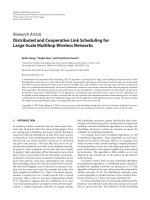
In addition to the handshake protocol described in the
previous section, the total number of messages exchanged
in sequential order is 4p + s(1 + p)+7,wheres is the
number of messages used for establishing an SSL connec-
tion and p is the number of proxies. If the cost of the
MC-SSL initial handshake protocol also counted, the to-
tal cost becomes 4p + s(2 + p) + 11 messages. For exam-
ple, the overall communication cost of establishing a proxy
channel with two proxies using SSL handshake (s is 12
messages) is 67 messages versus 36 messages needed for
client and server to connect through the same two prox-
ies using just three point-to-point SSL channels. Figure 10
shows the total communication cost (computed using the
latter expression) of establishing a multihop connection
for both MC-SSL and SSL. It suggests that the estab-
lishment of MC-SSL connections with few proxies costs
twice as much as for SSL. However, the overhead of MC-
SSL relative to SSL reduces as the number of proxies in-
creases.
After this extended handshake process is completed, if we
treat the structure in Figure 4 as a ring we can assure that ev-
ery entity has authenticated its two neighbours. As a result, C
can trust proxies from P
2
to P
n
,andS can trust proxies from
P
1
to P
n−1
, assuming the trust relation created through mu-
tual authentication is transitive. In the case of a single-hop
proxy channel, there is no need for transitive trust because C,
P,andS have directly authenticated one another. Although
the simplest protocol extension requires transitive t rust, we
expect it to be good enough for most applications because
proxy channels in MC-SSL are supposed to transport rela-
tively nonsensitive data. Sensitive data should be transported
using end-to-end channels.
10 EURASIP Journal on Wireless Communications and Networking
12345678910
Number of proxies
0
20
40
60
80
100
120
140
160
180
200
MC-SSL
SSL
Communication cost in messages
Figure 10: Communication cost of establishing simple multihop
proxy MC-SSL and SSL connections with transitive trust assump-
tion.
CS
P
1
P
n
R
C
R
C
+ R
P
1
R
C
+ R
P
1
+ + R
P
n
R = R
C
+ R
P
1
+ + R
P
n
+ R
S
(a)
CS
P
1
P
n
R, S
C
R, S
C
, S
P
1
R, S
C
, S
P
1
, S
P
2
, , S
P
n
S
C
, S
P
1
, S
P
2
, , S
P
n
(b)
Figure 11: The enhanced authentication: (a) generating random
string R, (b) signing R.
We can exclude the assumption of tr ansitive trust by ex-
panding the above negotiation process. If C and all proxies
have their own certificates, the modified protocol would con-
sist of the two stages illustrated in Figure 11. The intuition is
simple: generate a random number and ask C and all proxies
to sign the number using their private keys. The signatures
are circulated and used to verify the public key of each par-
ticipant by, potentially, each other.
Figure 11(a) shows the first stage, which generates a ran-
dom string that is a concatenation of random numbers pro-
duced by all the entities in the loop. The resulting string can
be denoted as R
= R
C
+ R
P1
+ R
P2
+ ···+ R
S
,whereR
i
is
a 32-byte cryptographically random string generated by entity
X, and “+” denotes the concatenation of two strings. This
process starts and ends at C. The message from C to P
1
con-
tains only R
C
, while the last message, which C receives from
S, is string R. In other words, each entity creates a random
number R
i
. All numbers merge into a single string R,which
is then signed by each entit y using the corresponding private
keys in the second stage. This method is actually an extension
of SSL, where only two entities (i.e., C and S) are involved in
the ring.
Figure 11(b) shows the second stage. S
i
denotes the sig-
nature generated by the ith entity. C sends P
1
a message that
contains the random string (R) generated in the first stage,
the certificate of C, and the digital signature (S
C
) generated
upon R with C’s private key. The signature can prove that
C is the key owner. Each proxy adds a new signature using
its private key; meanwhile, each proxy can verify C’s identity
using C’s certificate. When the message arrives at S,ithascol-
lected the signatures of all proxies, and therefore S can verify
all of them using their certificates. S can also forward them
to C if C wants to verify them as well. Section 5.3.1 claims
that the proxy in a single-hop proxy channel may not need
a PKI certificate since the session ID is randomly generated
by S. This is not t rue for a multihop proxy channel, however,
because any two neighbouring proxies have to authenticate
each other. A multihop proxy channel is more complex than
a single-hop one, and thus needs more support, such as pub-
lic keys, from the security infrastructure.
For the first stage, we add a new field in proxy-request
messages (PROXY
REQUEST
∗
in Figure 9) and the S-C
proxy finish message to carry the random string, a flag field to
indicate if S or C require verification of proxies’ certificates,
and another flag field to indicate if any proxy requires veri-
fication of C’s certificate. If no verification is requested, the
second stage will not start. For the second stage, we also in-
troduced a new message called CP
VERIFICATION to carry
forward all the necessary information, which ends with a
verification finish message (CP
VERI FINISH) from C to S.
While the messages of the first stage piggyback on proxy-
request messages, the second stage comes with an additional
cost of 2p + 2 messages and the same number of signature
generation and verification operations.
The protocol described above concerns the authentica-
tion of proxies and the client. We may also need to consider
the security issues of transporting and processing application
data through multiple proxies. For example, an application
might require that every chunk of data goes through every
designated proxy. To achieve this kind of data authenticity,
the client/server can ask proxies to “sign” a data chunk us-
ing their private key or MAC key. However, this requirement
introduces heavy computational costs in the case of many
proxies. Since a proxy channel is not supposed to transport
highly sensitive data unless all the proxies in the channel are
sufficiently trusted, we decided not to have additional data
authenticity protection at every proxy.
5.4. Secondary channel protocol
The protocols we have described so far do not support mul-
tiple cipher suites (a.k.a. secondary channels) in a point-to-
point connection. The only channel in a connection that
we have introduced is a primary channel provided by SSL.
Yong Song et al. 11
CP
1
P
n
S
SEC
CHAN REQ
SEC CHAN RESP
A
SEC
CHAN REQ
B
SEC
CHAN RESP
SEC
CHAN REQ
SEC
CHAN RESP
SEC
CHAN RESP
SEC
CHAN REQ
SEC
CHAN RESP
Figure 12: Negotiating secondary channels.
Message
type
Protocol
version
Channel ID Length Payload MAC
Coding /
decoding
{Cipher, hash algorithm}
Cipher suite
Mapping
Figure 13: Adding channel ID in an SSL packet.
This section describes the protocol for establishing secondary
channels. As defined in Section 4, every channel can have its
own cipher suite and channel direction.
5.4.1. Negotiation of secondary channels
Figure 12 shows the process of negotiating of secondary
channels. The negotiation of secondary direct channels is
shown in part A, and the negotiation of secondary proxy
channels is shown in part B. This protocol adds two mes-
sages to MC-SSL: the secondary-channel request message
(SEC
CHAN REQ) and the secondary-channel response
message (SEC
CHAN RESP). These messages are designed
to carry requests and responses for multiple secondary chan-
nels to reduce message interactions if an application session
needs multiple secondary channels. Additionally, the y are
designed to travel through primary channels. In MC-SSL,
channel-control messages never travel through secondary
channels, so that channel negotiation or management is as
secure as through primary channels provided by SSL.
ASEC
CHAN REQ message can specify the multiple
secondary channels to be requested. The message carries the
following information for each channel: the channel ID, a
list of cipher suites preferred by the message sender, and the
channel direction. It also carries the channel ID of the col-
laborative direct channel if the secondary channel is a proxy
channel. The collaborative direct channel of a proxy chan-
nel is the channel that an APP
DA T A CONTROL PROXY
message travels through, and it can b e the primary direct
channel or a secondary direct channel. An SEC
CHAN RESP
message carries the responses for channel requests in an
SEC
CHAN REQ message. Please refer to [20] for the mes-
sage formats of the secondary channel protocol. The overall
communication cost of establishing a secondary proxy chan-
nelis2p +5, where p is the number of proxies in the channel.
For MC-SSL to efficiently support multiple cipher suites,
a small extension is introduced to SSL. This extension is dis-
cussed in the next section. However, it is possible that the
actual SSL implementation at C or S does not support the ex-
tension. In this case, the above negotiation process will either
fail or not start, and secondary channels will not be available.
5.4.2. Extending SSL to support secondary channels
To multiplex several MC-SSL secondary channels in one SSL
connection, we add a new field, channel ID, in every SSL
packet header. When an SSL packet arrives, a receiver uses
the cipher suite corresponding to the channel ID to decrypt
and verify the payload encapsulated in the packet. Figure 13
illustrates an SSL packet and the relationship between chan-
nel ID, a cipher suite, and payload. The MC layer maintains
the mapping between channel ID and a cipher suite.
12 EURASIP Journal on Wireless Communications and Networking
Application layer
?
?
MC
SSL
Application layer
?
?
MC
SSL
Figure 14: Implementation of channel directions.
Introducing a channel ID necessitates several changes to
the SSL protocol. First, the calculation of MAC includes a
channel ID. Second, an SSL implementation needs to choose
the right cipher suite for each incoming packet according to
the channel ID field. Third, some functions in the SSL library
application programming interface (API) change: the write
function has a channel ID as an input par ameter, and the
read function returns as an output parameter the ID of the
channel from which the data comes.
Adding a channel ID field is a simple approach for sup-
porting multiple cipher suites, but the downside is that the
SSL header format has to be extended with an additional
field. In [20], we describe an alternative for realizing sec-
ondary channels. The advantage of this approach is that it
keeps the SSL protocol intact by “switching” the working ci-
pher suites with a simple handshake protocol at the upper
layer of MC-SSL. This technique changes a duplex channel
into two simplex channels with two working cipher suites.
Each endpoint maintains its own set of working cipher suites.
Since two working cipher suites are maintained for two op-
posite directions of SSL, MC-SSL does not need to switch ci-
pher suites in case one cipher suite is used for requests and a
different one for responses. In brief, this method can reduce
the frequency of switching cipher suites with the handshake
protocol, but it cannot eliminate channel renegotiation if an
application uses more than two simplex channels.
5.5. Restriction on channel directions
MC-SSL can restrict a channel’s data-flow direction. The
protocol defines four channel directions: duplex, client to
server, server to client,andnone. Duplex indicates a two-way
channel. The next two directions indicate a simplex channel
that allows application data to flow only from C to S or from
S to C.Directionnone is used for deactivating a channel. MC-
SSL inhibits any application data flow over an inactive chan-
nel. Note that a primary channel can be used for channel-
control messages in both directions even if it is marked as
client to server, server to client,ornone. This is because restric-
tion on channel directions applies only to application data
messages.
As shown in Figure 14, the restriction on channel di-
rections is enforced at the interface between the application
and the MC layers. If a channel is not duplex, it will reject
receiving data from and/or delivering data to the application
Initial
state
Initial handshake of MC-SSL
00
1
2
Data
reading
Data
writing
4
6
35
Channel
control
Send
proxy or
secondary
channel
request
Recieve
proxy or
secondary
channel
request
Handshake is finished
Figure 15: Basic state diagram of an MC-SSL session at a client or
server.
layer according to the specified channel direction. The under-
lying SSL layer is not aware of the channel directions imposed
by the MC layer. In fact, there could be another duplex chan-
nel inside the same SSL connection that allows both receiving
and delivering application data.
6. PROTOTYPE IMPLEMENTATION
To assess the feasibilit y of the MC-SSL architecture and
protocol, we have developed its prototype on Linux using
OpenSSL [21]. Based on the protocol design, the prototype
implementation has specified the message formats of MC-
SSL protocol as listed in [20, Appendix B]. The message for-
mats are defined using the language of TLS 1.0specification
[5].
After the initial MC-SSL handshake, the client and
server applications establish the primary end-to-end channel
through which they can start transporting application data
or negotiating other channels. Figure 15 shows the basic state
diagram of an MC-SSL session at C or S. There are four states
in the diagram. The exit state is omitted since an MC-SSL
session can exit from any state.
Starting from the initial state, an application could trans-
fer to the data-reading or data-writing state, depending on
the actual application protocol. For instance, an HTTP client
enters a data-writing state, and an HTTP (Web) server enters
a data-reading state. Applications at C or S can transfer be-
tween data-reading and data-wr iting states according to their
predefined application protocol.
C and S can issue a request message to set up or cancel
a channel at any time. As shown in Figure 15, MC-SSL au-
tomatically transfers from a data-reading state to a channel-
control state after receiving a channel request. In contrast,
it tr ansfers from a data-writing state to a channel-control
state when the application using MC-SSL calls an MC-SSL
API function to send a channel request. In the channel-
control state, MC-SSL is not supposed to receive or send any
Yong Song et al. 13
http proxy1
P
1
5677
TCP
Http client
C
TCP
5677
http
proxy2
P
2
TCP
5677
http
server p
File pipe
Http
server
S
5678
TCP
Figure 16: Prototype system diagram.
application data. When a channel-control process is finished,
MC-SSL immediately returns to the state it was in before en-
tering the channel-control state. As shown in Figure 15,if
MC-SSL enters the channel-control state via e dge 3, it goes
back to the data-reading state via edge 4; similarly, it goes
back to a data-writing state if it enters the channel-control
state via edge 5.
6.1. Prototype configuration
Figure 16 shows the system diagram of the prototype.
Server S is composed of two processes, http
server and
http
server p, both residing on the same host. The
http
server p is responsible for listening to and setting up
a connection between http
proxy2 and http server; there-
fore,itworkslikealocalproxyatS. The http
server and
http
server p processes communicate using a pair of file
pipes. The prototype assigns TCP port 5677 for proxy chan-
nels and TCP port 5678 for end-to-end channels. All server
and proxy server processes in the prototype are implemented
as multithreaded servers to provide HTTP over MC-SSL ser-
vices to several concurrent clients.
The prototype demonstrates that the proxy and sec-
ondary channels of MC-SSL can be implemented over SSL
and its extension. The prototype implementation of MC-SSL
can be further extended or simplified according to a spe-
cific application scenario. For instance, the C-P
1
connection
could run over the WTLS/WDP protocol stack if both C and
P
1
support the WAP protocol stack. Other details about the
proof-of-concept prototype can be found in [20].
7. CONCLUSIONS
This paper proposes multiple-channel SSL, a new architec-
ture and protocol that is an extension of SSL. MC-SSL has
three main features: first, it improves end-to-end security in
the presence of partially trusted application proxies; second,
MC-SSL supports secondary channels and channel direction
restrictions so that appropriate data protection can be se-
lectively applied to different data or content; third, MC-SSL
supports channel negotiation according to security policies,
device capabilities, and the security attributes of content. The
MC-SSL architecture is more flexible than SSL, and hence it
can better satisfy diverse requirements in different applica-
tion scenarios, especial ly for emerging mobile applications.
MC-SSL comes with its costs and gains. The higher per-
formance overhead is mainly due to the additional mes-
sages exchanged by the client, server, and proxies on top
of the established SSL channels. Once MC-SSL channels
are created, the only other performance cost is in the data
(de)multiplexing over multiple channels, which is very much
specific to the particular application and the number of sec-
ondary channels. Establishing a primary proxy channel costs
4p + s(2 + p) + 11 messages, where p is the number of proxies
and s is the communication cost (in number of messages) of
establishing each underlying SSL connection. Furthermore,
creating a secondary proxy channel costs another 2p+2 mes-
sages. A server experiences a total increase of 10 messages
(in addition to the SSL connections) that it has to either
generate or process when a client connects to it via proxies.
On the other hand, selective protection, as we discussed in
Section 4.1, can save CPU resources, a valuable asset for con-
strained mobile devices and overloaded servers. Depending
on what algorithms are negotiated for data encryption and
MAC protection, MC-SSL channels can commonly save 45%
to 90% of the CPU time spent on cry ptographic operations.
We expect that the benefits due to MC-SSL and the amortiza-
tion of the costs over long-lasting connections will outweigh
the costs of establishing channels and (de)multiplexing data.
The MC-SSL protocol presented in this paper is only one
possible implementation of MC-SSL architecture. The prin-
ciples and the architecture can be applied to improve WTLS
protocol or develop a counterpart protocol of MC-SSL for
UDP applications. One can develop a similar security proto-
col on top of UDP so that applications such as VoIP can make
use of proxy channels and multiple cipher suites. If two wire-
less terminals communicate with VoIP over RTP but do not
support the same voice coding or compression scheme, they
can use MC-SSL to set up a proxy for translating the voice
encoding. In addition, they can use different cipher suites for
user authentication and voice traffic.
ACKNOWLEDGMENTS
This work was supported by grants from Telus Mobility and
the Advanced Systems Institute of British Columbia and by
the Canadian Natural Sciences and Engineering Research
Council under Grant CRD247855-01. The authors would
like to thank Johnson Lee for conducting analysis of MC-SSL
savings [6] and Craig Wilson for improving the readability of
the paper.
14 EURASIP Journal on Wireless Communications and Networking
REFERENCES
[1] T. Dierks and C. Allen, “The TLS Protocol Version 1.0,” RFC
2246, January 1999.
[2] B. Schneier, Applied Cryptog raphy, John Wiley & Sons, New
York, NY, USA, 2nd edition, 1996.
[3] M. Y. Rhee, Internet Security : Cryptographic Principles, Algo-
rithms and Protocols, John Wiley & Sons, New York, NY, USA,
2003.
[4] WAP Forum, WAP 2.0 Specifications, nmo-
bilealliance.org/.
[5] S. Ravi, A. Raghunathan, and N. Potlapally, “Securing wireless
data: system architecture challenges,” in Proceedings of the In-
ternational Symposium on System Synthesis, pp. 195–200, Ky-
oto, Japan, October 2002.
[6]J.Lee,V.C.M.Leung,andK.Beznosov,“Analysisofscal-
able security–MC-SSL saving s,” Tech. Rep. LERSSE-TR-2005-
02, Laboratory for Education and Research in Secure Systems
Engineering (LERSSE), University of British Columbia, Van-
couver, BC, Canada, October 2005.
[7] M. Portmann and A. Seneviratne, “Selective security for TLS,”
in Proceedings of the 9th IEEE International Conference on Net-
works (ICON ’01), pp. 216–221, Bangkok, Thailand, October
2001.
[8] D. J. Kennedy, “An architecture for secure, client-driven de-
ployment of application-specific proxies,” M.S. thesis, Univer-
sity of Waterloo, Waterloo, Ontario, Canada, 2000.
[9] E. K. Kwon, Y. G. Cho, and K. J. Chae, “Integrated transport
layer security: end-to-end security model between WTLS and
TLS,” in Proceedings of 15th International Conference on Infor-
mation Networking, pp. 65–71, Oita, Japan, January-February
2001.
[10] W3C, XML Signature Recommendations, February 2002,
/>[11] W3C, XML Encryption Recommendations, December 2002,
/>[12] OASIS Open, “Web Services Security: SOAP Message
Security,” />php?wg
abbrev=wss, August 2003.
[13] OASIS Open, “Web Services Security X.509 Certificate To-
ken Profile,” working draft 11, October 2003, http://www.
oasis-open.org/committees/documents.php?wg
abbrev=wss.
[14] OASIS Open, “Web Services Security Kerberos Certificate To-
ken Profile,” working draft 03, January 2003, http://www.
oasis-open.org/committees/documents.php?wg
abbrev=wss.
[15] OASIS Open, “Web Services Security User name Token Pro-
file,” working draft 04, October 2003, is-open.
org/committees/documents.php?wg
abbrev=wss.
[16] C. Lesniewski-Laas and M. Frans Kaashoek, “SSL splitting: se-
curely serving data from untrusted caches,” in Proceedings of
the 12th USENIX Security Symposium, pp. 187–200, Washing-
ton, DC, USA, August 2003.
[17] W3C, HTML 4.01, December 1999, />html4/.
[18] W3C, XHTML 2.0, July 2004, />[19] G. Kiczales, J. Lamping, A. Mendhekar, et al., “Aspect-oriented
programming,” in Proceedings of the 11th European Conference
on Object-Oriented Programming, pp. 220–242, Jyvaskyla, Fin-
land, June 1997.
[20] Y. Song, “Multiple-channel security model and its implemen-
tation over SSL,” M.S. thesis, University of British Columbia,
Vancouver, BC, Canada, 2004, />search.py?recid
=94.
[21] OpenSSL Project, 2004, />Yong Song is a Database Engineer at
Datawave Services Inc., Richmond, BC,
Canada. He completed his Master’s degree
at the UBC in 2004 with the thesis on
“Multiple-Channel Security Model and Its
Implementation over SSL.” Prior to UBC,
Yong was a Software Engineer at Guang-
dong Telecommunication Academy of Sci-
ence and Technology, China. He also re-
ceived a Master’s degree from South China
University of Technology, and a Bachelor’s degree from Huazhong
University of Science and Technology, China.
Konstantin Beznosov is an Assistant Pro-
fessor at the Department of Electrical and
Computer Engineering, the U niversity of
British Columbia, where he founded and
directs the Laboratory for Education and
Research in Secure Systems Engineering
(lersse.ece.ubc.ca). His primar y research in-
terests are distributed systems security, se-
curity and usability, secure software engi-
neering, and access control. Prior to UBC,
Dr. Beznosov was a Securit y Architect with Quadrasis, Hitachi
Computer Products (America) Inc., where he designed and devel-
oped products for security integration of enterprise applications,
as well as consulted large telecommunication and banking com-
panies on the architecture of security solutions for distributed en-
terprise applications. Dr. Beznosov did his Ph.D. research on en-
gineering access control for distributed enterprise applications at
the Florida International University. He actively participated in
standardization of security-related specifications (CORBA Secu-
rity, RAD, SDMM) at the Object Management Group, and served
as a co-chair of the OMG’s Security SIG. Having published research
papers on security engineering in distributed systems, he is also a
coauthor of Enterprise Security w ith EJB and CORBA and Mastering
Web Se rvices Security both by John Wiley & Sons, Inc.
Victor C. M. Leung received the B.A.S.
(honors) and Ph.D. degrees, both in elec-
trical engineering, from the University of
British Columbia (UBC) in 1977 and 1981,
respectively. He was the recipient of many
academic awards, including the A PEBC
Gold Medal as the head of the 1977 grad-
uating class in the Faculty of Applied Sci-
ence, UBC, and the NSERC Postgraduate
Scholarship. From 1981 to 1987, Dr. Leung
was a Senior Member of Technical Staff at MPR Teltech Ltd. In
1988, he was a Lecturer in Electronics at the Chinese University
of Hong Kong. He returned to UBC as a faculty member in 1989,
where he is a Professor and holder of the TELUS Mobility Re-
search Chair in Advanced Telecommunications Engineering in the
Department of Electrical and Computer Engineering. His research
interests are in mobile systems and wireless networks. Dr. Leung
is a Fellow of IEEE and a Voting Member of ACM. He is an edi-
tor of the IEEE Transactions on Wireless Communications, an as-
sociate editor of the IEEE Transactions on Vehicular Technology,
and an editor of the International Journal of Sensor Networks.