Báo cáo hóa học: " Research Article Equalization of Multiuser Wireless CDMA Downlink Considering Transmitter Nonlinearity Using Walsh Codes" pdf
Bạn đang xem bản rút gọn của tài liệu. Xem và tải ngay bản đầy đủ của tài liệu tại đây (1.27 MB, 9 trang )
Hindawi Publishing Corporation
EURASIP Journal on Wireless Communications and Networking
Volume 2007, Article ID 49525, 9 pages
doi:10.1155/2007/49525
Research Article
Equalization of Multiuser Wireless CDMA Downlink
Considering Transmitter Nonlinearity Using Walsh Codes
Stephen Z. Pinter and Xavier N. Fernando
Department of Electrical and Computer Engineering, Ryerson University, Toronto, ON, Canada M5B 2 K3
Received 25 February 2006; Revised 11 November 2006; Accepted 13 November 2006
Recommended by David I. Laurenson
Transmitter nonlinearity has been a major issue in many scenarios: cellular wireless systems have high power RF amplifier (HPA)
nonlinearity at the base station; satellite downlinks have nonlinear TWT amplifiers in the satellite transponder and multipath con-
ditions in the ground station; and radio-over-fiber (ROF) systems consist of a nonlinear optical link followed by a wireless channel.
In many cases, the nonlinearity is simply ignored if there is no out-of-band emission. This results in poor BER performance. In
this paper we propose a new technique to estimate the linear part of the wireless downlink in the presence of a nonlinearity using
Walsh codes; Walsh codes are commonly used in CDMA downlinks. Furthermore, we show that equalizer performance is sig-
nificantly improved by taking into account the presence of the nonlinearit y during channel estimation. This is shown by using a
regular decision feedback equalizer (DFE) with both wireless and RF amplifier noise. We perform estimation in a multiuser CDMA
communication system where all users transmit their signal simultaneously. Correlation analysis is applied to identify the channel
impulse response (CIR) and the derivation of key correlation relationships is shown. A difficulty with using Walsh codes in terms
of their correlations (compared to PN sequences) is then presented, as well as a discussion on how to overcome it. Numerical
evaluations show a good estimation of the linear system with 54 users in the downlink and a signal-to-noise ratio (SNR) of 25 dB.
Bit error rate (BER) simulations of the proposed identification and equalization algorithms show a BER of 10
−6
achieved at an
SNR of
∼25 dB.
Copyright © 2007 S. Z. Pinter and X. N. Fernando. This is an open access article distributed under the Creative Commons
Attribution License, which permits unrestricted use, distribution, and reproduction in any medium, provided the original work is
properly cited.
1. INTRODUCTION
The quality of channel estimation has a prominent impact on
the accuracy of equalization and hence system performance.
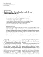
The general wireless CDMA downlink for cellular networks
is shown in Figure 1. In order to properly equalize this chan-
nel, an accurate estimation of both the nonlinear and linear
channel parameters is required. Some example systems are
cellular CDMA network downlink, radio-over-fiber (ROF)
[1] downlink, and satellite downlink. In all these cases, the
system of interest consists of a mildly nonlinear part followed
by a linear part, in that particular order. This interconnection
is considered a Hammerstein system. The breakdown of the
nonlinear/linear downlink systems as described above is the
following:
(1) wireless CDMA network downlink: RF amplifier/wire-
less channel;
(2) satellite downlink: TWT amplifier/wireless channel;
(3) ROF downlink: optical channel/wireless channel.
Some of the dominant issues associated with the above sys-
tems include intersymbol interference (ISI), RF amplifier
nonlinearity, and the presence of noise. In order to limit
the effects of these distort ions, estimation and subsequently
equalization of the concatenated channel should be done.
The most common approach is to ignore the nonlinearity
and just attempt to estimate the linear channel. This will re-
sult in inferior equalization performance. The goal in this
paper is to estimate first the channel parameters, and then
devi se appropriate equalization.
Some work in identifying Hammerstein systems has been
done by Billings and Fakhouri [2]. In [2], the Hammerstein
model was analyzed in a single control signal (or single user)
continuous-time baseband environment. Correlation analy-
sis was used to decouple the identification of the linear and
nonlinear component subsystems by using wh ite Gaussian
inputs. The generation of white noise inputs has practical
difficulties, therefore in this paper we substitute the white
Guassian inputs with the summation of multiple Walsh code
2 EURASIP Journal on Wireless Communications and Networking
Central base
station
RF amplifier
nonlinearity
F(
)
Access point
Multipath wireless
channel
To mobile unit
To mobile unit
To mobile unit
.
.
.
.
.
.
Figure 1: General wireless downlink.
F( )
q(t) r(t)
(a) Single complex-valued sys-
tem.
F
I
( )
F
Q
( )
q(t) r(t)
Σ
90
(b) Two real-valued systems.
Figure 2: Inphase and quadrature phase model for a nonlinear system.
sequences. We then apply the concept of Hammerstein rep-
resentation and correlation analysis to a multiuser CDMA
discrete-time passband communication system. The use of
Walsh codes for estimation of the downlink is attractive be-
cause these spreading codes are already widely used in spread
spectrum communications [3].
1
Any mildly nonlinear sys-
tem that can be described by an lth-order polynomial can be
identified using our technique. Other Hammerstein system
identification methods involve frequency domain techniques
[5], subspace-based state-space system identification [6], and
noniterative algorithms based on orthonormal functions [7].
The wireless downlink has a nonlinear element (e.g.,
HPA) common to all users, but each user will have a sep-
arate multipath wireless channel. We considered this mul-
tiuser scenario, where a summation of Walsh codes travels
through this concatenated channel. Following the channel
estimation, the downlink is equalized. A decision feedback
equalizer (DFE) is used to equalize for the wireless channel
dispersion. It is shown that equalizing for the nonlinearity is
not a strict requirement, however, consideration of the non-
linearity is required for the accurate estimation and equaliza-
tion of the linear channel.
Although the work in this paper is tailored to a multiuser
CDMA communication system, it can also be applied to areas
outside of the communication field where a parallel connec-
tion of multiple linear systems is encountered in series with
a single nonlinearity.
1
3G systems use scrambling codes as opposed to Walsh codes. Our ap-
proach is still justified since 3G downlink systems use both an initial
channelization code spreading (i.e., orthogonal Walsh code) followed by
a scrambling code spreading [4]. So in 3G downlink systems, Walsh codes
are still used, only in combination with scrambling codes, and we be-
lieve that system identification w i th Walsh codes will be of interest to re-
searchers in this area.
2. MULTIUSER CDMA DOWNLINK SYSTEM MODEL
In this section the theory for a multiuser CDMA downlink
will be presented with the help of discrete-time nonlinear
systems theory discussed in [2]. But before proceeding with
the estimation theory, a short section regarding complex no-
tation will be discussed.
2.1. Passband complex consideration
Communication signals and systems are passband. In order
to use baseband signal processing, communication signals
in the passband (i.e., real-valued signals [8]) must be ap-
propriately translated from the passband to the baseband.
Generally, this translation results in complex-valued base-
band signals [ 8]. Therefore, in a passband system, the sig-
nals as wel l as the channel impulse response (CIR) and non-
linear component are complex valued. We now show how
these complex-valued quantities can be split into real-valued
quadrature components for easy handling.
When an RF signal undergoes a nonlinear transforma-
tion one of the major concerns is the AM-AM and AM-
PM distortions. The complex-valued nonlinear system in
Figure 2(a) introduces both of these distortions [9]. It has
been shown in [10, 11] that a bandpass memoryless nonlin-
earity can be modeled with a baseband complex nonlinear
model. Then the nonlinear distortion can be expressed by
inphase and quadrature phase components that are real. Let
the input signal in Figure 2(a) be given as
q(t)
= A(t)cos
ω
c
t + θ(t)
. (1)
Then the output r(t)is
r(t)
= R
A(t)
cos
ω
c
t + θ(t)+φ
A(t)
,(2)
S. Z. Pinter and X. N. Fernando 3
x
1
(n)
x
2
(n)
x
N
(n)
F(
)
u(n) q(n)
n
amp
(n)
Σ
Σ
h
1
(n)
h
2
(n)
h
N
(n)
Σ
Σ
Σ
n
w(1)
(n)
n
w(2)
(n)
n
w(N)
(n)
r
1
(n)
r
2
(n)
r
N
(n)
.
.
.
.
.
.
.
.
.
.
.
.
Base station Nonlinearity
Access
point
Wireless channel
To m ob il e
units
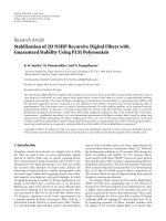
Figure 3: Downlink in a multiuser CDMA environment with a single nonlinearity (amplifier) and separate wireless channels for each user.
where R is the AM-AM distortion and φ is the AM-PM dis-
tortion. The output r(t) can also be expressed as
r(t)
= R
A(t)
cos
φ
A(t)
cos
ω
c
t + θ(t)
− R
A(t)
sin
φ
A(t)
sin
ω
c
t + θ(t)
,
(3)
using the trigonometric identity cos(A + B)
= cos(A)cos(B)
− sin(A) sin(B). Equation (3) can then be written as
r(t)
= r
i
A(t)
cos
ω
c
t + θ(t)
− r
q
A(t)
sin
ω
c
t + θ(t)
,
(4)
where
r
i
A(t)
= R
A(t)
cos
φ
A(t)
,
r
q
A(t)
=
R
A(t)
sin
φ
A(t)
.
(5)
Equation (4) shows that the bandpass nonlinearity can be
separated into an inphase component and a quadrature
phase component with only AM-AM distortion. Therefore,
the two real-valued systems shown by the quadrature model
in Figure 2(b) are equivalent to the complex-valued system
shown in Figure 2(a). Similarly, the bandpass CIR can also
be separated into inphase and quadrature phase components
[8].
Mathematically, real quantities are easier to work with
and therefore the quadrature model is the representation of
choice in this paper. As a result of this, it can be stated that
for the linear system in this paper the real-valued inphase and
quadrature phase components are estimated individually. All
variables introduced hereafter are real quantities unless oth-
erwise specified.
2.2. Wireless channel estimation theory
This section presents an investigation into the estimation of
the wireless channel of the downlink in a multiuser CDMA
environment using Walsh codes. As mentioned in Section 1,
the system of interest consists of a mildly nonlinear part
Table 1: Symbol descriptions for the downlink.
Symbol Description
x
j
(n) Input Walsh code spreading sequence, 1 ≤ j ≤ N
u(n) Compound Walsh sig nal input
F(·) Nonlinear function
n
amp
(n) RF amplifier Gaussian noise
q(n) Signal sent through multiple wireless channels
h
j
(n) Wireless channel impulse response, 1 ≤ j ≤ N
n
w( j)
(n) Wireless channel Gaussian noise, 1 ≤ j ≤ N
r
j
(n) Signal sent to mobile units, 1 ≤ j ≤ N
(HPA) followed by a linear part (wireless channel), w hich
can be modeled by a Hammerstein system. An investigation
into the single signal estimation of a Hammerstein system
has been covered in [ 2], but Gaussian inputs were used and
there was no extraction of the term R
uw
1
(σ). In this section,
the theory is extended to the multiuser case where varying
wireless channels are encountered for each mobile user. It is
also shown that multilevel testing (via the Vandermonde ma-
trix) alleviates anomalies that would otherwise be encoun-
tered with direct correlation.
The scenario of a multiuser CDMA downlink is shown
in Figure 3 (all signals u sed in analyzing the downlink, along
with their descriptions, are shown in Ta ble 1). In this sce-
nario: (1) the base station generates an independent Walsh
code for each user and combines them, (2) the combined sig-
nal is then transmitted through the common nonlinear link
followed by the addition of HPA noise, (3) the signal is then
transmitted through separate wireless channels followed by
the addition of an independent wireless channel noise,
2
and
2
Different “initial seed” settings are used during simulation to ensure in-
dependence.
4 EURASIP Journal on Wireless Communications and Networking
finally, (4) the signal is sent to the mobile user for further
processing. This scenario generates a multitude of signal im-
pairments such as: (1) ISI from the wireless channels, (2)
different path loss affecting dynamic range, (3) addition of
wireless and RF amplifier noise, and (4) carrier regrowth, in-
band distortion, and cross-multiplication of terms, all result-
ing from the nonlinearity.
The channel of interest in the estimation theory to follow
will be that of the first user, and so the output signal used
in all following derivations will be r
1
(n). The first step in the
estimation is to define the output of the system. According
to the theorem of Weierstrass [12], any function which is
continuous within an interval may be approximated to any
required degree of accuracy by polynomials in this interval.
Therefore, the output of the nonlinear system plus the am-
plifier noise is given by a polynomial of the form
q(n)
= A
1
u(n)+A
2
u
2
(n)+···+ A
l
u
l
(n)+n
amp
(n), (6)
where u(n) is a compound input of Walsh codes (of length
N
w
) that can be written as
u(n)
= x
1
(n)+x
2
(n)+···+ x
N
(n), (7)
where N is the number of Walsh codes (or equivalently the
number of users). The system output r
1
(n) can be expressed
by the convolution
r
1
(n) = q(n) ∗ h
1
(n)+n
w(1)
(n). (8)
Substituting for q(n)from(6) and expanding the convolu-
tion give
r
1
(n) = A
1
∞
m=−∞
h
1
(m)u(n − m)+A
2
∞
m=−∞
h
1
(m)u
2
(n − m)
+
···+ A
l
∞
m=−∞
h
1
(m)u
l
(n − m)
+
∞
m=−∞
h
1
(m)n
amp
(n − m)+n
w(1)
(n),
(9)
which can be written in a more compact form as
r
1
(n) =
l
k=1
A
k
∞
m=−∞
h
1
(m)u
k
(n − m)
+
∞
m=−∞
h
1
(m)n
amp
(n − m)+n
w(1)
(n)
noise terms
.
(10)
As a summation of the output of the isolated lth order kernel,
the above equation becomes
r
1
(n) = w
1
(n)+w
2
(n)+w
3
(n)+···+ w
l
(n) + noise terms.
(11)
Expressing the output in the form of (11)isacrucialstep
in developing the correlation relationships that follow. By
studying the correlation between the output r
1
(n) and the in-
put u(n), as well as the output of the first-order kernel w
1
(n)
and the input u(n), the linear and nonlinear systems can be
estimated.
3. CORRELATION RELATIONSHIPS
The next step in the estimation of the concatenated channel
is to further process the input-output relations, as defined
above, by utilizing correlation relationships.
3.1. Generalized input-output correlation
A commonly defined output is used in this derivation. The
output is given by r(n), where r(n)
= r
j
(n), 1 ≤ j ≤ N.
Using the input u(n) and the general output r(n), the cross-
covariance between them can be written as
R
ur
(σ) =
r(n) − r(n)
u(n − σ) − u(n − σ)
. (12)
The cross-covariance relationship is used widely throughout
this section. From this point onward, r(n), q(n), n
amp
(n),
u(n), and x
j
(n), n
w( j)
(n)for1≤ j ≤ N will refer to their re-
spective signals with the mean removed. In some cases [12],
a mean level is added to the input to ensure that both odd
and even terms in (11) contribute to the first-order input-
output cross-correlation. However, in this case, only the out-
put of the first-order kernel is of interest (discussed shortly)
and hence a mean level is not needed. With means removed,
the cross-covariance can be written as
R
ur
(σ) = r(n)u(n − σ). (13)
Substituting (11) into the above equation and assuming the
input and noise processes to be statistically independent, that
is,
n
amp
(n)u(n − σ) = 0forallσ and n
w( j)
(n)u(n − σ) = 0for
all σ,give
R
ur
(σ) =
w
1
(n)+w
2
(n)+···+ w
l
(n)
u(n − σ)
=
w
1
(n)u(n−σ)+w
2
(n)u(n−σ)+···+w
l
(n)u(n−σ)
= w
1
(n)u(n−σ)+w
2
(n)u(n−σ)+···+w
l
(n)u(n−σ)
= R
uw
1
(σ)+R
uw
2
(σ)+···+ R
uw
l
(σ),
(14)
which can be written in a more compact form as
R
ur
(σ) =
l
k=1
R
uw
k
(σ). (15)
However , if R
ur
(σ) is evaluated directly as defined above, the
terms
l
k
=2
R
uw
k
(σ) give rise to anomalies associated with
multidimensional autocovariances [13]. This problem can be
overcome by isolating R
uw
1
(σ) using multilevel input test-
ing. This step is crucial for successful estimation of the wire-
less channel. Multilevel testing is possible under the condi-
tion that the output can be expressed by (11). It should be
noted that if the channels were linear there would be no need
to isolate R
uw
1
(σ)becauseR
uw
1
(σ) = R
ur
(σ).
Multilevel testing is implemented prior to the nonlin-
earity by using the signal α
m
u(n), where α
m
= α
l
for all
m
= l, and repeating l times. For example, with a third-order
S. Z. Pinter and X. N. Fernando 5
nonlinearity, the output at the mobile user can be written as
r(n)
=
A
1
u(n)+A
2
u
2
(n)+A
3
u
3
(n)+n
amp
(n)
∗
h
1
(n)
+ n
w( j)
(n)
= A
1
u(n) ∗ h
1
(n)+A
2
u
2
(n) ∗ h
1
(n)
+ A
3
u
3
(n) ∗ h
1
(n)+n
amp
(n) ∗ h
1
(n)+n
w( j)
(n)
= w
1
(n)+w
2
(n)+w
3
(n) + noise terms.
(16)
With the multilevel input α
1
u(n), the above equation be-
comes
r
α
1
(n) =
A
1
α
1
u(n)+A
2
α
2
1
u
2
(n)+A
3
α
3
1
u
3
(n)+n
amp
(n)
∗ h
1
(n)
+ n
w( j)
(n)
= A
1
α
1
u(n) ∗ h
1
(n)+A
2
α
2
1
u
2
(n) ∗ h
1
(n)
+ A
3
α
3
1
u
3
(n) ∗ h
1
(n)+n
amp
(n) ∗ h
1
(n)+n
w( j)
(n)
= α
1
w
1
(n)+α
2
1
w
2
(n)+α
3
1
w
3
(n) + noise terms,
(17)
which when used to find R
ur
(σ) gives the following modified
form of (15):
R
ur
α
m
(σ) =
l
k=1
α
k
m
R
uw
k
(σ), m = 1, 2, , l (18)
where r
α
m
is the response of the system to multilevel inputs.
An important condition when using multilevel inputs is
that the number of multilevel inputs used should be equal
to the highest polynomial order. This ensures that the algo-
rithm works in the presence of any order nonlinear function.
Representing (18)inmatrixformgives
⎡
⎢
⎢
⎢
⎢
⎢
⎢
⎢
⎢
⎣
R
ur
α
1
(σ)
R
ur
α
2
(σ)
·
·
R
ur
α
l
(σ)
⎤
⎥
⎥
⎥
⎥
⎥
⎥
⎥
⎥
⎦
=
⎡
⎢
⎢
⎢
⎢
⎢
⎢
⎢
⎢
⎣
α
1
α
2
1
··α
l
1
α
2
α
2
2
··α
l
2
·····
·····
α
l
α
2
l
··α
l
l
⎤
⎥
⎥
⎥
⎥
⎥
⎥
⎥
⎥
⎦
⎡
⎢
⎢
⎢
⎢
⎢
⎢
⎢
⎢
⎣
R
uw
1
(σ)
R
uw
2
(σ)
·
·
R
uw
l
(σ)
⎤
⎥
⎥
⎥
⎥
⎥
⎥
⎥
⎥
⎦
. (19)
To check the above α matrix for singularities, it is divided
into two matrices as follows:
⎡
⎢
⎢
⎢
⎢
⎢
⎢
⎢
⎢
⎣
α
1
0 ·· 0
0 α
2
0 · 0
· 0 ·· 0
·····
00··α
l
⎤
⎥
⎥
⎥
⎥
⎥
⎥
⎥
⎥
⎦
⎡
⎢
⎢
⎢
⎢
⎢
⎢
⎢
⎢
⎣
1 α
1
α
2
1
· α
l−1
1
1 α
2
α
2
2
· α
l−1
2
·· ·· ·
·· ·· ·
1 α
l
α
2
l
· α
l−1
l
⎤
⎥
⎥
⎥
⎥
⎥
⎥
⎥
⎥
⎦
. (20)
The matrix on the left-hand side (LHS) of (20)isclearly
nonsingular for α
m
= 0. The matrix on the r ight-hand
side (RHS) of (20) is the Vandermonde matrix which has a
nonzero determinant given by
1≤i<j≤l
α
j
− α
i
, (21)
for α
i
= α
j
. Therefore, for every value of σ,(19) has a unique
solution for R
uw
i
(σ), i = 1, 2, , l. Now that R
uw
1
(σ) (the
input-kernel correlation) can be extracted, the final step in
the identification process is to find how R
uw
1
(σ)relatesto
the CIR.
3.2. Difficulties with the input-kernel correlation
The cross-covariance between the compound input u(n)and
w
1
(n)canbewrittenas
R
uw
1
(σ) = w
1
(n)u(n − σ). (22)
Substituting for w
1
(n)from(10) and expanding u(n)give
R
uw
1
(σ)
=
A
1
∞
m=−∞
h
1
(m)u(n − m)
u(n − σ)
=
A
1
∞
m=−∞
h
1
(m)u(n − m)u(n − σ)
(23)
= A
1
∞
m=−∞
h
1
(m)
x
1
(n−m)+x
2
(n−m)+···+ x
N
(n−m)
×
x
1
(n − σ)+x
2
(n − σ)+···+ x
N
(n − σ)
.
(24)
Theaboveequationcanbeconsideredintwoways:(1)byex-
panding u(n), giving (24), and (2) without expanding u(n),
giving (23).
3.2.1. Expanding u(n)
Simplifying (24) using correlation notation gives
R
uw
1
(σ)
= A
1
∞
m=−∞
h
1
(m)
R
x
1
x
1
(m − σ)+R
x
2
x
2
(m − σ)
+
···+ R
x
N
x
N
(m − σ)+R
x
i
x
j(j=i)
(m − σ)
.
(25)
Since Walsh codes do not have well-defined mathematical
correlation properties, the above equation cannot be fur-
ther simplified. Individually, Walsh codes have good corre-
lation properties only when tig htly synchronized and even
then it is only at the zeroth lag . As the lag moves away from
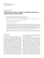
zero, the correlation becomes unacceptable. This is repre-
sented in Figure 4. This figure shows the autocovariance and
cross-covariance properties of two individual Walsh codes,
one with a code index of 396 and the other with a code index
of 882. From Figures 4(a) and 4(b) it is clear that the autoco-
variance properties of individual Walsh codes are unaccept-
able. For this reason, identification of the concatenated chan-
nel in a single user Walsh code environment is difficult. But
the situation drastically changes when many users are con-
sidered at once.
3.2.2. Without expanding u(n)
The covariance properties of the summation of Walsh codes
are very much different from that of the covariance of indi-
vidual Walsh codes. It has been found through simulations
6 EURASIP Journal on Wireless Communications and Networking
1000
500
0
500
1000
1500
Amplitude
1000 500 0 500 1000
Lag
(a) Autocovariance of Walsh code of index 396.
1000
500
0
500
1000
1500
Amplitude
1000 500 0 500 1000
Lag
(b) Autocovariance of Walsh code of index 882.
150
100
50
0
50
100
150
Amplitude
1000 500 0 500 1000
Lag
(c) Cross-covariance of the above two Walsh codes.
Figure 4: Covariance properties of individual Walsh codes of length
2
10
for two different code indices.
that, as more and more users are added, this compound in-
put of Walsh codes starts to resemble a white noise-like pro-
cess. This is an interesting outcome because it is known that
identification of the downlink is possible under the condi-
tion that the input is white noise-like (see [2, 13]). The au-
tocovariance of the input u(n) is shown in Figure 5.Thereis
some resemblance observed between this autocovariance and
that of a PN sequence, given by R
x
i
x
i
(λ) = N
c
δ
i
(λ). Aside
from the amplitudes at nonzero lags, the autocovariance of
the summation of Walsh codes can be approximated by the
1
0
1
2
3
4
5
6
10
4
Amplitude
1000 500 0 500 1000
Lag
Figure 5: Autocovariance of a summation of Walsh codes.
relationship
3
R
uu
(λ) ≈ N
w
Nδ(λ), (26)
where N is the number of Walsh codes. Applying the above
approximation to (23)gives
R
uw
1
(σ) = A
1
N
w
N
N
w
−1
m=0
h
1
(m)δ(m − σ). (27)
Using the convolution properties of the impulse function
gives
R
uw
1
(σ) = A
1
N
w
Nh
1
(σ) (28)
where the estimated CIR can be found by solving the above
expression. T herefore, it has been shown that the CIR can
be estimated by utilizing the autocovariance property of
summed Walsh codes. Using a greater number of Walsh
codes results in even better covariance properties and hence
a more accurate identification.
4. ESTIMATION: SIMULATION RESULTS
AND DISCUSSION
The simulation package used for all simulations herein
was MATLAB with Simulink. The simulations were per-
formed with Figure 3 implemented as a Simulink model. The
Simulink model was used mainly as a means to gather the
input-output data of the system. All the initializations and
identification calculations (i.e., correlations) were performed
in MATLAB by sending the Simulink inputs/outputs to the
MATLAB workspace.
4
3
Under the condition that the code indices for the Walsh codes occupy
the entire range of indices available for that certain code length, in equal
intervals.
4
MATLAB and Simulink are the trade names of their respective owners.
S. Z. Pinter and X. N. Fernando 7
4.1. Simulation parameters and
channel characteristics
4.1.1. CIR and polynomial
All CIRs used in the simulations satisfied the property of unit
energy, that is,
n
|h(n)|
2
= 1. This ensured no amplification
from the wireless channel.
The major source of nonlinearity is the RF amplifier,
which can be modeled using an lth-order polynomial. Any
mildly nonlinear system that can be described by an lth-order
polynomial can be identified using our technique. For exam-
ple, in the case of ROF, the polynomial is third-order with a
saturating characteristic (see [14, 15]).
4.1.2. Number of users and Walsh code length
Fifty four users were simulated at the base station. Simu-
lations were performed with a Walsh code length of 1024
(N
w
= 2
10
).
4.1.3. Noise
The SNR between the base station and access point was set to
25 dB, and the wireless noise power for each mobile user was
set equal to the amplifier noise power.
4.1.4. Cross-covariance
Lang and Chen showed in [16] that, for 10th degree se-
quences, the average Walsh code cross-covariances are ap-
proximately 2.53 times larger than PN sequence cross-
covariances. However, the adverse effect of these cross-
covariances is minimal because they are relatively small when
compared to the large autocovariance value. This can also be
seen by comparing Figures 4(c) and 5. From these figures it is
found that the maximum amplitude of the cross-covariance
is approximately 0.208% of the maximum autocovariance.
4.1.5. Quality of fit
The quality of fit of the estimated CIR to the actual CIR was
measured by defining a normalized estimation error param-
eter
ρ
=
L
k=0
h
actual
(k) − h
est
(k)
2
L
max
, (29)
where L
max
is the largest CIR memory amongst all users.
Dividing by L
max
makes ρ independent of CIR memory. A
smaller ρ means a better CIR estimate.
4.1.6. Synchronous communication
Synchronization can be achieved for all signals in the down-
link. The buffer period needed for the simulation of asyn-
chronous communication is not needed. All signals can start
at the same time and data is collected from the start of the
simulation to the end (i.e., the time needed to cover one pe-
riod, N
w
).
0.6
0.4
0.2
0
0.2
0.4
0.6
0.8
Amplitude
0 5 10 15 20 25 30 35 40 45
Delay (nT
c
)
Actual CIR
Estimated CIR
Figure 6: “Poor” channel impulse response (CIR) estimate.
0.4
0.2
0
0.2
0.4
0.6
0.8
1
Amplitude
0 5 10 15 20 25 30 35 40 45
Delay (nT
c
)
Actual CIR
Estimated CIR
Figure 7: “Good” channel impulse response (CIR) estimate with
ρ
= 1.462 × 10
−4
.
4.2. Wireless channel identification
Two CIR estimates are presented in this section, they are de-
fined as “good” and “poor.” The reason for this is to show that
at this point there is still an inconsistency between estimates
and that the quality of the estimate depends on the charac-
teristics of the CIR (a major factor being the spread between
multipath arrivals). Note that the linear CIRs have been es-
timated in the presence of a nonlinearity. We performed a
large number of trials by varying the gain of each path using
the Rayleigh fading model. The worst and the best case esti-
mation errors from these trials were ρ
= 4.241 × 10
−3
and
ρ
= 1.462 × 10
−4
. These two cases are shown in Figures 6
and 7, respectively. Most of the time ρ was smaller than the
8 EURASIP Journal on Wireless Communications and Networking
Channel Equalizer
n
amp
(n)
+/
1
n
w
(n)
x(n)
Base
station
Nonlinearity
Wireless
channel
r(n)
F(
) h(n)ΣΣDFE
q(n)
q(n)
Figure 8: Block diagram for downlink equalization.
mean value, which we found gives a reasonably good chan-
nel estimate. Note that since there is a greater spread between
multipath arrivals in the “poor” estimate of Figure 6, the al-
gorithm is not so accurate but it is still able to recover the
general structure of the desired CIR.
4.3. Nonlinearity identification
Once the CIRs are known, the internal signal q(n)mustbe
estimated so that polynomial fitting can be done between the
signals u(n)and
q(n). The accuracy of the nonlinear identi-
fication is highly dependent on the CIR estimates and so it
is important that the CIR estimation algorithm works well.
One possible method to estimate the internal signal is by de-
convolving h
1, ,N
(n) with their respective outputs r
1, ,N
(n).
Estimating the nonlinearity is left for future work.
5. HAMMERSTEIN-TYPE DOWNLINK EQUALIZATION
The downlink has a static nonlinearity followed by a dynamic
linear time dispersive wireless channel. This is a Hammer-
stein system. Although the nonlinear portion of the Ham-
merstein system has not been estimated, equalization can still
be performed on the linear w ireless channel of the downlink.
The structure of the equalizer is shown in Figure 8. The re-
ceiver consists only of a DFE arrangement that compensates
solely for the wireless channel dispersion. Even though the
polynomial is not compensated for, the simulation results of
the equalization still show a good improvement in terms of
bit error rate (BER). Note that the equalization is done for
a single user, but the channel is estimated under a multiuser
environment. The nonlinearity is common for all the users;
however, the wireless channel varies for different users.
The number of DFE taps was derived based on the mem-
ory of the CIR (L was varied from 9 to 13). In order to com-
pletely eliminate postcursor interference, the number of FBF
taps must satisfy the condition K
2
≥ L [8]. The number of
FFF taps is chosen to be approximately 2L (which is com-
mon in the literature). Hence, the DFE parameters for the
simulations were as follows: FFF taps were varied from 18 to
26 and FBF taps were varied from 9 to 13.
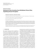
A large number of error rate simulations were performed
and the BER from an “average” CIR estimate was found. Sim-
ulations were also done to find the BER resulting from not
taking the nonlinearity into account during the channel esti-
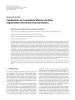
mation process. These two BERs are plotted in Figure 9.We
can see from this figure that a very good improvement in
10
9
10
8
10
7
10
6
10
5
10
4
10
3
BER
10
15 20 25 30 35
SNR (dB)
“Average” CIR estimate (nonlinearity not considered)
“Average” CIR estimate
Figure 9: BER of the downlink using the “average” CIR estimate;
this is the most realistic outcome.
the BER can be achieved with the proposed algorithm which
takes the nonlinearity into account during channel estima-
tion.
When the channel has a few strong paths (typical in a
rural environment with few buildings) the proposed non-
linear channel estimation works very well. Figure 10 shows
this best case (when the estimation error is small). Under this
scenario the performance error is even better. An acceptable
BER for transmitting data is 10
−6
. Our algorithm can achieve
this BER at an SNR of about 25 dB (with the “good” CIR esti-
mate), which is comparable to the DFE BER curves obtained
in [8, 17].
This paper shows the usefulness of an estimation algo-
rithm that takes into account the nonlinear nature of the
channel.
6. CONCLUSION
This paper presented a method for identification of the mul-
tiuser CDMA downlink using the correlation properties of
Walsh codes. We improved the single user identification per-
formed in [2] to accommodate multiple users and we showed
S. Z. Pinter and X. N. Fernando 9
10
9
10
8
10
7
10
6
10
5
10
4
10
3
BER
10
15 20 25 30 35
SNR (dB)
“Good” CIR estimate (nonlinearity not considered)
“Good” CIR estimate
Figure 10: BER of the downlink using the “good” CIR estimate.
the effect of both wireless and RF amplifier noise. It was
shown that using a summation of Walsh codes, as opposed to
single Walsh codes, makes identification of the Hammerstein
system possible. In a synchronous CDMA environment, the
proposed identification algorithm works well with 54 users,
and even better with additional users because the correlation
property improves. Equalization of the downlink showed a
BERof10
−6
achieved at an SNR of ∼ 25 dB.
Some concerns regarding the practicality of the estima-
tion algorithm arise when considering the effect that mul-
tilevel testing has at the system level. However, with power
control algorithms used in CDMA systems, the multilevel
transmission is inherently done. For example, when a mo-
bile unit moves away from the base station, its received power
will drop; the base station will then increase the transmitted
power (typically in 1dB steps) until the power is acceptable.
So, one of our ideas to overcome this problem of multilevel
testing is to record data during the adjustment of power with
power control algorithms. Assuming there is little change in
the wireless channel impulse response while gathering data,
this technique can provide the multile vel testing required for
estimation.
REFERENCES
[1] X. N. Fernando and S. Z. Pinter, “Radio over fiber for broad-
band wireless access,” PHOTONS: Technical Re view of the
Canadian Institute for Photonic Innovations,vol.2,no.1,pp.
24–26, 2004.
[2] S. A. Billings and S. Y. Fakhouri, “Non-linear system identifi-
cation using the Hammerstein model,” International Journal of
Systems Science, vol. 10, no. 5, pp. 567–578, 1979.
[3] H. Al-Raweshidy and S. Komaki, Radio Over Fiber Technolo-
gies for Mobile Communications Networks,ArtechHouse,Nor-
wood, Mass, USA, 1st edition, 2002.
[4] M. W. Oliphant, “Radio interfaces make the difference in 3G
cellular systems,” IEEE Spectrum, vol. 37, no. 10, pp. 53–58,
2000.
[5] E W. Bai, “Frequency domain identification of Hammerstein
models,” in Proceedings of the 41st IEEE Conference on Deci-
sion and Control, vol. 1, pp. 1011–1016, Las Vegas, Nev, USA,
December 2002.
[6] J.C.G
´
omez and E. Bae yens, “Subspace identification of mul-
tivariable Hammerstein and Wiener models,” in Proceedings of
the 15th IFAC World Congress, Barcelona, Spain, July 2002.
[7] J.C.G
´
omez and E. Baeyens, “Identification of block-oriented
nonlinear systems using orthonormal bases,” Journal of Process
Control, vol. 14, no. 6, pp. 685–697, 2004.
[8]J.G.Proakis,Digital Communications, McGraw-Hill, New
York, NY, USA, 4th edition, 2001.
[9] X. N. Fernando and A. B. Sesay, “Adaptive asymmetric lin-
earization of radio over fiber links for wireless access,” IEEE
Transactions on Vehicular Technology, vol. 51, no. 6, pp. 1576–
1586, 2002.
[10] A. A. M. Saleh, “Frequency-independent and frequency-
dependent nonlinear models of TWT amplifiers,” IEEE Trans-
actions on Communications, vol. 29, no. 11, pp. 1715–1720,
1981.
[11] X. N. Fernando, “Signal processing for optical fiber based
wireless access,” Ph.D. dissertation, University of Calgary, Cal-
gary, Alberta, Canada, 2001.
[12] S. A. Billings and S. Y. Fakhour i, “Identification of a class of
nonlinear systems using correlation analysis,” Proceedings of
the IEE, vol. 125, no. 7, pp. 691–697, 1978.
[13] S. A. Billings and S. Y. Fakhouri, “Identification of nonlinear
systems using correlation analysis and pseudorandom inputs,”
International Journal of Systems Science, vol. 11, no. 3, pp. 261–
279, 1980.
[14] P. Raziq and M. Nakagawa, “Semiconductor laser’s nonlinear-
ity compensation for DS-CDMA optical transmission system
by post nonlinearity recovery block,” IEICE Transactions on
Communications, vol. E79-B, no. 3, pp. 424–431, 1996.
[15] X. N. Fernando and A. B. Sesay, “Fibre-wireless channel esti-
mation using correlation properties of PN sequences,” Cana-
dian Journal of Electrical and Computer Engineering, vol. 26,
no. 2, pp. 43–47, 2001.
[16] T. Lang and X H. Chen, “Comparison of correlation parame-
ters of binary codes for DS/CDMA systems,” in Proceedings of
the IEEE International Conference on Communications Science
(ICCS ’94), vol. 3, pp. 1059–1063, Singapore, November 1994.
[17] X. N. Fernando and A. B. Sesay, “A Hammerstein-type equal-
izer for concatenated fiber-wireless uplink,” IEEE Transactions
on Vehicular Technology, vol. 54, no. 6, pp. 1980–1991, 2005.