Báo cáo hóa học: " Research Article Implementation of Wireless Communications Systems on FPGA-Based Platforms" pptx
Bạn đang xem bản rút gọn của tài liệu. Xem và tải ngay bản đầy đủ của tài liệu tại đây (756.51 KB, 9 trang )
Hindawi Publishing Corporation
EURASIP Journal on Embedded Systems
Volume 2007, Article ID 12192, 9 pages
doi:10.1155/2007/12192
Research Article
Implementation of Wireless Communications Systems on
FPGA-Based Platforms
K. Masselos
1
and N. S. Voros
2, 3
1
Department of Computer Science and Technology, University of Peloponnese, Terma Karaiskaki, 22100 Tripolis, Greece
2
INTRACOM TELECOM Solutions S.A., 254 Panepistimiou Street, 26443 Patra, Greece
3
Department of Communication Systems and Networks, Technological Educational Institute of Mesolonghi,
Ethniki Odos Antiriou Nafpaktou, Var ia, 30300 Nafpaktos, Greece
Received 4 June 2006; Revised 27 November 2006; Accepted 27 November 2006
Recommended by Thomas Kaiser
Wireless communications are a very popular application domain. The efficient implementation of their components (access points
and mobile terminals/network interface cards) in terms of hardware cost and design time is of great importance. T his paper de-
scribes the design and implementation of the HIPERLAN/2 WLAN system on a platform including general purpose micropro-
cessors and FPGAs. Detailed implementation results (performance, code size, and FPGA resources utilization) are presented. The
main goal of the design case presented is to provide insight into the design aspects of a complex system based on FPGAs. The
results prove that an implementation based on microprocessors and FPGAs is adequate for the access point part of the system
where the expected volumes are rather small. At the same time, such an implementation serves as a prototyping of an integrated
implementation (System-on-Chip), which is necessary for the mobile terminals of a HIPERLAN/2 system. Finally, firmware up-
grades were developed allowing the implementation of an outdoor wireless communication system on the same platform.
Copyright © 2007 K. Masselos and N. S. Voros. This is an open access article distributed under the Creative Commons Attribution
License, which permits unrestricted use, distribution, and reproduction in any medium, provided the original work is properly
cited.
1. INTRODUCTION
There have been several standardization efforts in wireless
communications (including GPRS, EDGE, and UMTS), the
goal of which was to meet the increasing requirements of
users and applications. In the unlicensed band of 2.45 GHz
the IEEE 802.11b [1] standard has provided to the users up
to 11 Mbit/s transmission rates. The IEEE 802.11a [2] and the
HIPERLAN/2 [3] protocols were specified to provide data
rates of up to 54 Mbit/s for short-range (up to 150 m) com-
munications in indoor and outdoor environments.
There are two types of devices associated with a WLAN
system: the access point and the mobile terminal (network
interface card). The estimated worldwide number of ship-
ments for the period 2003–2005 for HIPERLAN/2 and IEEE
802.11a network interface cards was expected to be around
37 million pieces plus and their price was expected to be less
than 70 USD by 2005 [4]. The corresponding numbers for
access points were estimated to about 5.4 million pieces with
prices less than 250 USD by 2005 [4]. From the estimated
quantity of shipments and prices it becomes clear that an im-
plementation based on discrete components is possible for
the access points while network interface cards require an in-
tegrated System-on-Chip solution (also for size and power
consumption reasons).
Due to the high computational complexity of WLAN sys-
tems and the capabilities of state-of-the-art microprocessors,
an implementation based solely on microprocessors would
require a large number of components and would be
cost inefficient. FPGAs with their spatial/parallel compu-
tation style can significantly accelerate complex parts of
WLANs and improve the efficiency of discrete components
implementations. The advantage of the discrete compo-
nents implementation over a System-on-Chip implementa-
tion for low volume production is related both to the com-
ponents cost (bill-of-material) and to the design effort. Ex-
cept from the above advantages, in the access point side there
are no strict size and power consumption constraints that
would impose a System-on-Chip implementation. Further-
more given the important similarities of the access points and
mobile terminals (network interface cards) functionalities in
systems like HIPERLAN/2 and IEEE 802.11a, an implemen-
tation of an access point using microprocessors and FPGAs
2 EURASIP Journal on Embedded Systems
Rate
dependent
puncturing P2
Rate
independent
puncturing P1
Convolutional
encoder
Data
scrambler
MAC/PHY
interface
Interleaver
Constellation
mapper
Pilot
insertion
IFFT
Cyclic
prefix
insertion
PHY
burst
formation
Preambles
Figure 1: HIPERLAN/2 transmitter block diagram.
Constellation
decoder
Channel
estimation and
frequency domain
equalization
FFT
Cyclic
prefix
extraction
Timing and frequency
synchronization and
correction
MAC/PHY
interface
Descrambler
Viterbi
decoder
Rate
independent
depuncturing
Rate
dependent
depuncturing
De-interleaver
Figure 2: HIPERLAN/2 receiver block diagram.
can also serve as a prototyping for a System-on-Chip imple-
mentation for the network interface cards.
In this paper the implementation of the HIPERLAN/2
access point functionality on the ARM integrator platform
[5] is described. ARM integrator includes a number of ARM
processor-based modules and a number of FPGA-based
modules organized around an AMBA bus located in the main
board. The aim of the implementation is to prove the feasibil-
ityofacostefficient implementation of the HIPERLAN/2 ac-
cess point system using discrete components. Furthermore,
useful conclusions can be derived towards the realization of
a System-on-Chip targeting both access points and network
interface cards. Final ly, the flexibility offered by the imple-
mentation platform was exploited for the implementation of
a system for outdoor wireless communications on the same
hardware.
The rest of the paper is organized as follows. Section 2
provides an overview of the HIPERLAN/2 system. Section 3
provides details on the functional specification of the system;
while Section 4 details the architecture exploration phase.
Section 5 presents concrete results for the final system imple-
mentation; while Section 6 provides the conclusions of the
paper.
2. OVERVIEW OF HIPERLAN/2 WLAN SYSTEM
The HIPERLAN/2 system [3, 6, 7]iscomposedoftwotypes
of devices: the mobile terminals (network interface cards) and
the access points.
The HIPERLAN/2 medium access control (MAC) is a
centrally scheduled TDMA/TDD scheme. The MAC frame
has a fixed duration of 2 ms and consists of the following
phases: broadcast (BC) phase, downlink (DL) phase, uplink
(UL) phase, direct link phase (DiL), and random access phase
(RA). The functionality of the HIPERLAN/2 DLC/MAC layer
is control dominated (timed state machines).
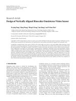
The baseband part of the physical layer of HIPER-
LAN/2 is based on orthogonal frequency division multi-
plexing (OFDM) [8]. Reference block diagrams of HIPER-
LAN/2 transmitter and receiver are presented in Figures 1
and 2, respectively. The types of operations and the com-
putational complexities (for all the different physical layer
modes) of the different baseband processing tasks are pre-
sented in Tables 1 and 2. Indicative computational complex-
ities are given in million operations per second—MOPS (as-
suming that all operations, e.g., arithmetic, logical are treated
the same).
3. FUNCTIONAL SPECIFICATION OF
HIPERLAN/2 SYSTEM
Given that the architecture exploration focuses on the MAC
sublayer and the physical layer, which are the most complex
ones, a detailed ANSI-C model has been developed for each
of them in order to offer a refined input to the architecture
exploration stage. The size of the ANSI-C model is 20000
lines of code. The structure of the code is shown in Figure 3.
K. Masselos and N. S. Voros 3
Table 1: Computational complexity of transmitter tasks in different physical layer modes.
Task Type of processing
Computational complexity (MOPS)/PHY mode (Mb/s)
6 9 1218273654
Scrambling bit level-shift register, XOR 108 162 216 324 486 648 972
Convolutional
encoding
bit level-shift register, XOR 174 261 348 522 783 1044 1566
Puncturing
(rate independe nt)
bit level-logic operations 0.31 0.31 0.31 0.31 0.31 0.31 0.31
Puncturing
(rate dependent)
bit level-logic operations 0 33 0 66 105 132 198
Interleaving Group of bits-LUT accesses 48 48 96 96 192 192 288
Constellation
mapping
Group of bits-LUT accesses 30 45 36 54 54 72 90
Pilot insertion Word level-memory accesses 56 56 56 56 56 56 56
IFFT
Word level-multiplications,
additions, memory accesses
922 922 922 922 922 922 922
Cyclic prefix insertion Word level-Memory accesses 72 72 72 72 72 72 72
Sum
— 1410 1599 1746 2112 2670 3138 4164
Table 2: Computational complexity of receiver tasks in different physical layer modes.
Task Type of processing
Computational complexity (MOPS)/PHY mode (Mb/s)
6 9 12 18 27 36 54
Cyclic prefix extraction Word level-me mory accesses 96 96 96 96 96 96 96
Frequency error
correction
Word level-multiplications,
additions, memory accesses
208 208 208 208 208 208 208
FFT
Word level-multiplications,
additions, memory accesses
922 922 922 922 922 922 922
Frequency domain
equalization
Word level-multiplications,
additions, memory accesses
132 132 132 132 132 132 132
Constellation demapping Group of bits-LUT accesses 48 48 240 240 288 288 336
Deinterleaving
Group of bits-LUT accesses 48 48 96 96 192 192 288
Depuncturing
(rate dependent)
bit level-logic operations 0 50 0 99 118 198 297
Depuncturing
(rate independe nt)
bit level-logic operations 0.16 0.20 0.16 0.20 0.28 0.20 0.20
Viterbi decoding
Bit le vel I/O-word level
additions, comparisons
1170 1755 2340 3510 5265 7020 10530
Descrambling bit level-shift register, XOR 108 162 216 324 486 648 972
Sum
— 2732 3421 4250 5627 7707 9704 13781
The structure of the ANSI-C model is shown in Figure 6.
The model of the baseband processing part of HIPERLAN/2
system is divided into two parts: complex numbers based algo-
rithms (mapping, OFDM, PHY bursts) and binary algorithms
(scrambling, FEC, interleaving). In the ANSI-C model, the
baseband processing submodules are designed as pipelined
procedures with unit data processing. A number of con-
figuration parameters are supported for the physical layer
modules (e.g . , width and position of point in fixed point
numbers, number of soft bits in Viterbi algorithm, time syn-
chronization threshold, duration and time outs, size fo inter-
nal buffers, etc.).
The submodules of the physical layer are implemented as
procedures, which get as standard parameters: request type,
command, command parameters and data. Shared data are
representedasglobalvariables.Eachphysicallayermodule
4 EURASIP Journal on Embedded Systems
MA C layer
Feedback controllerPHY controller
Command Feedback
PHY layer
RSS
Transmit
Binary
algorithms
Receive
Receive/request
Control/information
Enable/disable
RSS measurement
Transmit
Complex-based
analysis
Receive
Control
RSS
Tx
power
Carrier
frequency
Rx
gain
RSS
Transmit
Radio
interface
Receive
Control
Data
Data + control
Figure 3: Structure of the ANSI-C model of the targeted function-
ality.
calls the next one, when the data portion requested by the
next module interface is ready.
In contrast to physical layer, MAC layer’s module inter-
communication is activated when a logically finished data
structure is completely ready. Information is transferred in
the form of memory pointers, or copied to some buffer.
4. ARCHITECTURE EXPLORATION
Architecture exploration is related to the stages of the design
flow that link high-le vel specifications with implementation
detailed design steps (HDL coding for hardware, C/C++ cod-
ing for software). The major decisions made during archi-
tecture exploration include the allocation of different types
of processing resources and the assignment of the targeted
functionality tasks on the allocated resources. Given the com-
plexity of modern applications, making such decisions in a
nonsystematic way (i.e., based on designer’s experience) and
with no tool support leads, in most cases, to implementa-
tions that either do not meet the system’s constraints, or are
cost inefficient, or both. Systematic architecture exploration
methods are essential to ensure correct architecture decisions
early enough in the design flow, in order to eliminate the
time consuming iterations from low-level design stages in the
cases where performance and cost constraints are not met.
There are basically two types of architecture explor a tion ap-
proaches: the tool oriented design flow and the language ori-
ented design flow. Example of a tool oriented design flow is
the N2C by CoWare [9]. In the design flows supported by
such tools, the refinement process of a design from unified
and un-timed model towards RTL is tool specific. Examples
of language oriented design flows are OCAPI-xl [10]andSys-
temC [11]. Language-based approaches are more flexible and
give the designer more freedom.
4.1. The OCAPI-xl environment
The architecture exploration for the HIPERLAN/2 system
has been p erformed using OCAPI-xl C++ library [10].
OCAPI-xl is a C++ based design environment for develop-
ment of concurrent, heterogeneous HW/SW applications.
It abstracts away the heterogeneity of the underlying plat-
form through an intermediate-language layer that provides
a unified view on SW and HW components. The language
is directly embedded in C++ via a creatively designed set
of classes and overloaded operators, and has an abstraction
level between assembler and C. The computational model of
OCAPI-xl relies on processes. Different types of processes are
supported.
4.2. Architecture exploration for the access point of
the HIPERLAN/2 system
In the context of the HIPERLAN/2 access point system, ar-
chitecture exploration does not commence from scratch.
This is mainly due to the fact that we have to develop the
system in a way that is compatible with other products of
the same family. For that reason, the starting point of archi-
tecture exploration phase is a generic implementation archi-
tectural template that includes a number of ARM processors
and a number of hardware accelerators (corresponding to
FPGAs in the final implementation platform). Global com-
munication is performed using a centralized AMBA bus.
Using the ANSI-C model as input, OCAPI-xl models of
the HIPERLAN/2 MAC sublayer and the baseband part of the
physical layer have been developed. For the high-level explo-
ration, the high-level OCAPI-xl processes (procHLHW, proc-
ManagedSW, and procHLSW) have been used to model the
timing behavior of the HIPERLAN/2 tasks under different
abstract implementation scenarios (on generic hardware and
software processors). For the software computation models
(procManagedSW and procHLSW) a simple processor model
(resembling the targeted ARM architecture) has been devel-
oped. The system partitioning and mapping to processors
approach is simple. The different tasks of the targeted sys-
tem are assigned to different hardware (procHLHW)orsoft-
ware (procManagedSW, procHLSW) abstract processors. The
abstract implementations are evaluated using system perfor-
mance estimates (in terms of execution cycles) obtained by
OCAPI-xl and through area cost estimates. Using this ap-
proach, different mappings of HIPERLAN/2 tasks on hard-
ware and software have been evaluated and the most promis-
ing solution has been identified.
K. Masselos and N. S. Voros 5
Table 3: Part of architecture exploration for the baseband processing part of HIPERLAN/2 using the OCAPI-xl approach.
Mapper Interleaver IFFT Puncturing Scrambler
Conv.
encoder
Code
terminator
Feedback
controller
Performance
in cycles
HW cost
1 HLSW HLSW HLSW HLSW HLSW HLSW HLSW HLSW 1242881 8 processors
2
HLHW HLSW HLSW HLSW HLSW HLSW HLSW HLSW 1242188
7 processors +1
HW accelerator
3 HLHW HLHW HLSW HLSW HLSW HLSW HLSW HLSW 1120320
6 processors +2
HW accelerators
4 HLHW HLHW HLHW HLSW HLSW HLSW HLSW HLSW 34613
5 processors +3
HW accelerators
5 HLHW HLHW HLHW HLHW HLSW HLSW HLSW HLSW 33265
4 processors +4
HW accelerators
6 HLHW HLHW HLHW HLHW HLHW HLSW HLSW HLSW 33183
3 processors +5
HW accelerators
7 HLHW HLHW HLHW HLHW HLHW HLHW HLSW HLSW 25454
2 processors +6
HW accelerators
8 HLHW HLHW HLHW HLHW HLHW HLHW HLHW HLSW 13504
1 processor +7
HW accelerators
9 HLHW HLHW HLHW HLHW HLHW HLHW HLHW HLHW 12348 8 HW accelerators
The process followed for partitioning and mapping on
hardware and software of the HIPERLAN/2’s access point
system models is detailed in the sequel through two simpli-
fied examples.
4.2.1. Physical layer
Eight critical processes of the transmitter are considered:
mapper, interleaver, inverse FFT, puncturing, scrambler, con-
volutional encoder, code terminator, feedback controller .
One of the operational scenarios considered during archi-
tecture exploration concerns the transmission of four PDU
trains (one SCH and three LCH) from the access point to the
mobile terminal. The timing constraint for this operation ac-
cording to the standard is 254 μs.
At the beginning of the partitioning/mapping process all
the processes are modeled as procHLSW corresponding to
an implementation with eight parallel software processors
(ARMs), one for each process. The simulation of the OCAPI-
xl model gives an estimate of 1242881 cycles for the com-
pletion of this operation. Assuming a conservative clock fre-
quency of 50 MHz (cycle 20 ns) for the ARM processors, we
get a time estimate of 24857.62 μs which is far greater than
the 254 μs constraint. It must be noted that if all processes
are modeled as procManagedSW, corresponding to an im-
plementation on a single software processor shared among
the processes under the control of an operating system, the
execution time estimates would be f ar worse. Except from
the timing issue, an implementation with 8 software pro-
cessors is also cost inefficient. In the next steps of the ex-
ploration, the processes are moved one after the other to
hardware accelerators (modeled as procHLHW) leading to
execution time speed up and also cost reduction (since it is
reasonable to assume that the cost of an accelerator is smaller
than the cost of the generic software processor correspond-
ing to ARM). When all processes are moved to hardware, the
estimated number of execution cycles is 12348 leading to an
estimated execution time of 246.96 μs (assuming clock fre-
quency of 50 MHz) which is within the timing constraint.
Thus we can conclude that the given processes need to be
accelerated and assigned on hardware. The detailed results of
this process are presented in Ta ble 3.
4.2.2. MAC sublayer
In the case of the MAC sublayer of the HIPERLAN/2 ac-
cess point system, the critical processes are access point re-
ceiver and access point command handler. One of the scenar-
ios evaluated during the architecture exploration is the re-
ception of a Broadcast Channel PDU. According to this, a
BCH PDU (which appears at the beginning of each HIPER-
LAN/2 frame) is being received and passed to the upper
RLC sublayer. According to the HIPERLAN/2 standard, the
time constraint for the specific action is 36 μs. The explo-
ration of the various alternatives commences by allocating
both processes to software (i.e., they are characterized in
OCAPI-xl as procHLSW). The simulation of the OCAPI-xl
model resulted in an estimation of 25.287 cycles for execut-
ing the specific scenario. Assuming a conservative clock fre-
quency of 50 MHz for the ARM processors, we get a time
estimate of 505.74 μs which is far greater than the limit of
36 μs. As already explained in the case of the physical layer,
the possibility of modeling all the processes as procMan-
agedSW would result to even worse execution times. The
simulation results illustrated in Table 4 exhibit all the alter-
native allocation schemes explored. A brief look reveals that
6 EURASIP Journal on Embedded Systems
Table 4: Part of architecture exploration for the MAC sublayer of HIPERLAN/2 using the OCAPI-xl approach.
Receiver Command handler Performance in cycles Execution time (μs) HW cost
1 HLSW HLSW 25.287 505.74 2 processors
2
HLHW HLSW 1.268 25.36 1 processor +1 HW accelerator
3
HLSW HLHW 8.986 179.72 1 processor +1 HW accelerator
4
HLHW HLHW 876 17.52 2 HW accelerators
Core module #1
Core module #2
Protocol processor
SRAM
controller
AHB bus
interface
SRAM
controller
AHB bus
interface
SRAM SRAM
AMBA AHB
ARM integrator
Top l o gic
module
Tx path & Rx time
domain, MAC/PHY
interface
Analog
IF
RF
Bottom logic
module
Rx data &
frequency domain
System control FPGA
AMBA arbiter
Ethernet controller
PCI controller
External bus interface
ARM-related blocks
Lower MAC & modem
control processor
Figure 4: Architecture of selected ARM integrator platform instance (in core module 2 change modem to physical layer).
alternatives (1) and (3) violate the constraint of 36 μs. Al-
ternatives (2) and (4) result in 25.36 μs and 17.52 μs, respec-
tively, for the specific scenario, which is b elow the constraint
of 36 μs. Among the two, case (2) is cost efficientsinceitis
not implemented purely in hardware, and as a result, it is the
one finally selected.
In the next step, the high-level OCAPI-xl model of the
selected architecture has been refined. The refinement in-
cluded the change of processes’ types from high level to low
level (procOCAPI1 and procANSIC). This allowed a cycle ac-
curate simulation of the complete system functionality and
confirmation that timing constraints are met.
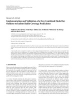
Based on (a) the architecture exploration results, (b)
the analysis of the HIPERLAN/2 computational complex-
ity, and (c) performance constraints, two core modules and
two logic modules have been allocated for the realization
of the HIPERLAN/2 system. Each core module includes an
ARM7TDMI processor and each logic module includes a
Xilinx Virtex E 2000 FPGA [12]. The architecture of the
ARM Integrator instance that has been selected for the re-
alization of the HIPERLAN/2 system is shown in Figure 4.
One ARM processor (core module #1, indicated as proto-
col processor in the figure) implements convergence layer
and higher DLC, that is, the functionality that was not con-
sidered during architecture exploration. The second ARM
processor (core module #2 in the figure) implements MAC
sublayer functionality and physical layer control functional-
ity. The two FPGAs (logic modules) implement critical parts
of MAC sublayer and the digital part of the physical layer.
The functionality of HIPERLAN/2 has been assigned to the
allocated processing resources based on the selected assign-
ment derived during the architecture exploration procedure
presented above.
Although OCAPI-xl appears to be a promising approach
for architecture exploration, there are some issues that must
be taken care of in order to allow OCAPI-xl’s effective use
in the context of real world case studies. For example, in the
HIPERLAN/2 access point system it was difficult for the de-
signers to create detailed models for the AMBA bus. Lack
of such features could result in loss of accuracy during sys-
tem model design and refinement, which in turn may lead to
misleading results during the architecture exploration phase.
K. Masselos and N. S. Voros 7
Table 5: Execution times for basic tasks of HIPERLAN/2 DLC/MAC layer (where CL: convergence layer, Tx: transmitter, Rx: receiver).
BCH/FCH decoder modem Ctrl MAC layer tasks Exec. Time (µs) DLC tasks Exec. Time
Initialization phase (reset & config @ slot commands) 1.20 Scheduler 0.2 ms
Synchronization phase (BCH
SRCH, Rx FCH with
rpt
= 1, Rx ACH)
2.65 TxCL 0.6 ms
BCH decoding and BCH CRC checking 5.25 TxBuilder (full frame) 0.7 ms
Decoding of a single IE (UL)
3.23
TxBuilder copy using DMA
(580 bytes-word transfer)
15 μs
Decoding of 3 IEs (2 ULs, 1 DL) including CRC
checking & puncturing
15 Rx Decoder 0.4 ms
— —RxCL0.7ms
In the case of HIPERLAN/2 access point, the designers had
to use external detailed models of AMBA bus which are
connected to the OCAPI-xl models through FLI interface
(FLI stands for foreign language interface and is a feature of
OCAPI-xl that allows incorporation of external code into an
OCAPI-xl model [10]).
5. IMPLEMENTATION RESULTS
As soon as the architecture decisions have been made, the
next stage is related to the system implementation. Both
hardware and software developments were carried out man-
ually without exploiting the code genera tion capabilities of
OCAPI-xl (VHDL and ANSI-C). This was in order to achieve
as optimized implementations as possible.
For the tasks assigned to software processors, C++ code
has been developed and mapped on the ARM7TDMI proces-
sors of the core modules. The code developed includes 262
C++ classes (9 top level) for the access point. The tools used
for the software development process include the Code War-
rior IDE, the ARM, THUMB C and Embedded C++ com-
pilers, the ARM Extended Debugger, and the ARMulator in-
struction set simulator.
The execution times for the basic tasks of HIPERLAN/2
DLC/MACarepresentedinTa ble 5. The results have been
obtained with an operation frequency of 50 MHz (cycle
20 ns). The code a nd the data for the tasks are stored in
SDRAM memory. The size of the code running on the proto-
col processor is 1.4 Mbytes while the size of the code running
on the second processor is 50 Kbytes.
For the tasks assigned to hardware, VHDL code has been
developed. The VHDL description of the complete function-
ality includes 250 VHDL modules (different levels of hierar-
chy). A typical FPGA flow has been adopted for realization
of the tasks assigned on the platform’s logic modules. The
tools used include ModelSim (simulation), Leonardo spec-
trum (synthesis), and Xilinx ISE tools (back end design).
The detailed architecture of the functionality realized by
the logic modules of the prototyping platform is shown in
Figure 5. In the first FPGA (bottom log ic module) the fre-
quency and data domain blocks of the receiver are mapped.
The total utilization of the first FPGA is 85%. The second
Table 6: Utilization per resource type for the two logic modules
FPGAs.
Resource
Used Utilization (%)
Bottom
logic
module
Top
logic
module
Bottom
logic
module
Top
logic
module
I/Os 93 312 18.16 60.93
Function
generators
14923 16527 38.86 43.04
CLB slices 12164 11252 63.35 58.60
DFFs or latches 6368 8544 15.60 20.94
FPGA (Top logic module) includes the transmitter, the time
domain blocks of the receiver, the interface to MAC, and
a slave interface to an AMBA bus. The total utilization of
the second FPGA is 89%. The utilization per resource type
for the first and second FPGAs is presented in Tabl e 6.Two
clocks of 40 and 80 MHz are driven in each FPGA. The size
of the configuration files for the two FPGAs is 1, 2 Mbytes.
The performance results presented above, from the real-
ization of the HIPERLAN/2 system on the ARM Integrator
platform, are expected to improve in a possible SoC imple-
mentation. This is due to the overheads introduced by the
ARM Integrator platform architecture (FIFOs of the bus in-
terface, SDRAM controller, etc.), and also due to the lack of
a local bus for the communication between the physical layer
hardware and the protocol processor. Additionally, the pro-
tocol ARM in the integrator platform communicates with the
physical layer hardware and the networking ARM through
the AMBA bus, sharing the bus bandwidth with those units.
That bottleneck has put the real time performance of the pro-
totyping system in danger.
Other important issues that will need to be considered
in case of development of a HIPERLAN/2 SoC for mobile
terminals include the clocking strategy, design for testabil-
ity, and debugging circuitry and strategy. Also low power is-
sues for the fixed logic part of the SoC should be applied to
achieve a competitive perfor mance.
In order to fully realize the HIPERLAN/2 access point,
the ARM Integrator platform was connected to an IF
(20 M Hz to 880 MHz) and an RF (880 MHz to 5 GHz) stage.
8 EURASIP Journal on Embedded Systems
NCS RF Analog IF
ADC
DAC
ICS670
(low PN
PLL)
80/60
MHz PM
CLK
CLK
60/80
Clocks
domain
B
Clocks
domain
A
Clocks
domain
A
Logic module top
ARM integrator
logic modules
partitioning
RF reference
clock domain
System bus
clock domain
ICS525
(PLL)
ICS525
(PLL)
24 MHz
ICS525
(PLL)
ICS525
(PLL)
24 MHz
Rx in
Rx
out
Rx
cmd
SYSCLK0
SYSCLK
SYSCLK0
SYSCLK
AMBA
master & slave
Rx
DMA
SYSCLK[3 : 0]
SYSCLK[3 : 0]
AMBA
slave
I, Q
modem
XCV2000E
XCV2000E
CLK
A30
CLK
A30
CLKB
60/80
Tx
Tx
mem
Rx
mem
I/F
EXPB
EXPB
30 MHz
30 MHz
Buffer
350MHz
PCI CLK cPCI CLK
UART CLK
ICS525
(PLL)
ICS525
(PLL)
ICS525
(PLL)
24 MHz
Motherboard
Logic module bottom
Figure 5: FPGA-based architecture using ARM integrator.
The analog-to-digital and digital-to-analog conversions (na-
tional semiconductors LMX5301 and LMX5306), for com-
municating with the IF analog front ends of the receiver
and the transmitter, respectively, have been implemented on
a separate board which seats on a dedicated connector for
external communications on the “top” of the stack of logic
modules. Also the communication with the PCI or Ethernet
interface is done through that port.
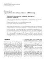
Figure 6 shows a photograph illustrating the ARM In-
tegrator platform along with the IF, RF boards a nd the
antenna, which are required for the implementation of
the HIPERLAN/2 access point. The implementation of
the HIPERLAN/2 access point on the discrete compo-
nents platform also allows the algorithmic performance
evaluation (for the physical layer) through field measure-
ments.
The implementation of the HIPERLAN/2 system on a
platform with general purpose microprocessors and FP-
GAs allowed the extension of the system functionality in a
second step. More specifically, using the same DLC/MAC
architecture a proprietary system for outdoor wireless com-
munications in the 5 GHz band has been evaluated. The
baseband part of the physical layer was modified compared
to that of HIPERLAN/2. The blocks that were modified
are the synchronization and channel estimation blocks of
the receiver, the FFT/IFFT block (a 256 points FFT is re-
quired for outdoor environments compared to the 64 points
FFT/IFFT used in HIPERLAN/2) and the decoder block
in the receiver (a Reed Solomon needs to be added to
the Viterbi decoder of HIPERLAN/2). The modified base-
band part for outdoor communications system was im-
plemented on the FPGAs of the implementation platform
and it was proved that it can still fit in these devices
(this is because the utilization of these devices is around
85% for the HIPERLAN/2 case leaving free some resources
for the extra complexity of the outdoor system baseband
block). With some extra software modifications it is possi-
ble to have a system with two modes of operation (indoor-
outdoor) that share the same hardware in a time multiplexed
way.
K. Masselos and N. S. Voros 9
Core modules
AtoDandDtoA
conversion
board
Top logic module
Bottom logic module
ARM integrator motherboard
IF board
RF board
Antenna
Figure 6: ARM integrator platform along with the IF, RF boards and the antenna.
6. CONCLUSIONS
The design and implementation of a HIPERLAN/2 access
point on a platform based on microprocessors and FPGAs
have been discussed. The implementation requires in total
two ARM7 microprocessors and two Xilinx E FPGAs. The
expected bill of materials for an implementation based on
thistypeofcomponentsisexpectedtobe100USDoreven
lower. An access point implementation using the same SoC
as for a network interface card (but with different software)
would allow a significant reduction in access point prices. In
a next step firmware upgrades were developed for the imple-
mentation of an outdoor wireless communication system on
the same hardware in a time multiplexed way. This would
further reduce the total cost of the dual system access point.
REFERENCES
[1] IEEE Std 802.11b, “Part 11: Wireless LAN Medium Access
Control (MAC) and Physical Layer (PHY) specifications:
Higher-Speed Physical Layer Extension in the 2.4 GHz Band,”
1999.
[2] IEEE Std 802.11a, “Part 11: Wireless LAN Medium Access
Control (MAC) and Physical Layer (PHY) specifications: High
Speed Physical Layer in the 5 GHz Band,” 1999.
[3] ETSI TS 101 457, “Broadband Radio Access Networks
(BRAN); HIPERLAN Type 2; Physical (PHY) layer”.
[4] Cahners-In-Stat, “Life, Liberty and WLANs: Wireless Net-
working Brings Freedom to the Enterprise,” November 2001.
[5] ARM Integrator, 2005, />integrator.
[6] ETSI TS 101 761-1, “Broadband radio access networks
(BRAN); HIPERLAN Type 2; Data Link Control (DLC)
layer—Part 1: Basic data transport functions,” 2000.
[7] ETSI TS 101 761-2, “Broadband Radio Access Networks
(BRAN); HIPERLAN Type 2; Data Link Control (DLC)
Layer—Part 2: Radio Link Control (RLC) sublayer,” V1.3.1,
2002.
[8] R. van Nee and R. Prasad, OFDM for Mobile Multimedia Com-
munications, Artech House, Boston, Mass, USA, 1999.
[9] CoWare, 2005, />[10] OCAPI-xl, 2005, />ds025.pdf.
[11] SystemC, 2005, />[12] Xilinx, “Virtex
TM
Data Sheet,” 2005, inx.
com/xlnx/xweb/xil
publications index.jsp.