Báo cáo hóa học: " Research Article Geometry Unit for Analysis of Warped Image Features on Programmable Chips" ppt
Bạn đang xem bản rút gọn của tài liệu. Xem và tải ngay bản đầy đủ của tài liệu tại đây (897.93 KB, 8 trang )
Hindawi Publishing Corporation
EURASIP Journal on Embedded Systems
Volume 2007, Article ID 37317, 8 pages
doi:10.1155/2007/37317
Research Article
Geometry Unit for Analysis of Warped Image Features on
Programmable Chips
Johannes F
¨
urtler,
1
Konrad J. Mayer,
1
Christian Eckel,
2
J
¨
org Brodersen,
1
Herbert Nachtnebel,
3
and Gerhard Cadek
2
1
Business Unit of High Performance Image Processing, Austrian Research Centers Gmbh-ARC, 2444 Seibersdorf, Austria
2
Oregano Systems - Design and Consulting GmbH, Phor usgasse 8, 1040 Vienna, Austria
3
Institute of Computer Technology, Vienna University of Technology, Gußhausstraße 27-29/E384, 1040 Vienna, Austria
Received 1 May 2006; Revised 13 October 2006; Accepted 30 October 2006
Recommended by Udo Kebschull
Among many constraints applicable for embedded visions systems in industrial applications, desired processing performance is a
determining factor of system costs. For technically and economically successful solutions, it is essential to match algorithms and
architecture. High-end field programmable gate arrays open the perspective to vision systems on a programmable chip, leading
to reduced size and higher performance. The architecture proposed in our previous publications in 2004 and 2006 is based on
reusable building blocks. This paper continues with a particular building block for backward warping and interpolation of ar-
bitrary shaped image regions, which can be used for many image processing tasks, including image statistics, projections, and
template matching. The architecture is discussed and a typical application for template matching is presented. The suggested unit
serves as universal basis for high-level image processing implemented on programmable chips, which enables a new generation of
integrated high performance embedded vision systems maintaining reasonable system costs due to design reuse of basic units.
Copyright © 2007 Johannes F
¨
urtler et al. This is an open access article dist ributed under the Creative Commons Attribution
License, which permits unrestricted use, dist ribution, and reproduction in any medium, provided the original work is properly
cited.
1. INTRODUCTION
Today, computer vision embedded in industrial inspection
systems enables efficient production processes and can opti-
mize profitability. Improvement of efficiency means higher
throughput, often together with the requirement for en-
hanced accuracy of the inspection process. This leads to
a huge demand of processing power to cope with high
data rates and to execute challenging image processing algo-
rithms. On the other hand, typical constraints are the size of
hardware, (real-time) requirements of the application, and,
of course, system cost. Size is important, because vision sys-
tems have to be embedded into machines where space for
the vision hardware is often limited. The (real-time) require-
ments of the application define the desired behavior of the
embedded vision system, therefore, in many cases the image
processing system has to be optimized for numerous param-
eters. However, most design issues can be expressed in terms
of costs. Consequently, a design process where functional as-
pects of the system are reasonably mapped to hardware mod-
ules and software modules is essential for a technically real-
izable and economically powerful embedded vision system.
This paper deals with a particular aspect of an image
processing system used for industrial print inspection [1–3].
In this application, the embedded vision system consists of
several high-speed/high-resolution cameras, each acquiring
hundreds of megabytes of data per second, and a scalable
processing system which is able to compute a quality decision
for every sheet processed by the machine. The processing sys-
tem must handle feeding rates of up to 50 sheets per second,
which leads to a time frame of 20 milliseconds for the im-
age processing tasks. The key issue for the design of such an
image processing system is to match algorithms and archi-
tecture. It is essential to find a balance between algorithms
implemented in hardware and algorithms r unning as soft-
ware tasks. This can be achieved by following common hard-
ware/software design methodologies. For practical imple-
mentation, high-end field programmable gate arrays (FPGA)
enable very complex designs on a single chip [4]. In con-
junction with common design principles like parallel pro-
cessing, pipelining, and multiport memory concepts, pow-
erful image processing systems on a programmable chip can
be implemented [5]. To reach the goal of optimal processing
2 EURASIP Journal on Embedded Systems
performance, it was advantageous to pay attention to avail-
able FPGA resources (e.g., DSP blocks, memory blocks, on-
chip CPU, and so on) as early as possible in the design pro-
cess. Hence, dedicated resources have to be considered in the
design specification.
By the integration of complete image processing systems
on an FPGA, the size of embedded v ision systems can be
considerably reduced, because multiple modules, previously
implemented on dedicated integr a ted circuits, are now on
the same chip. A big advantage of FPGAs is the possibil-
ity to implement various functional units which are work-
ing in parallel favoring algorithms where parallelization can
be exploited. This enables higher overall processing speeds
than can be realized with a single high-end digital signal
processor (DSP), despite its typically higher clock frequency.
Hence, many image processing tasks can be implemented
on an FPGA, completely eliminating the need for DSPs in
some applications. In addition, FPGA systems can be recon-
figured, even at runtime, to meet dedicated application de-
mands. Consequently, one hardware platform can be used
for several applications, simply by reconfiguring the FPGA.
Design reuse is the main factor to reduce costs by shortening
the development cycle for the embedded vision system. As
a result, we propose an architecture where an inspection sys-
tem is based on (simple) building blocks which are appropri-
ately interconnected according to the underlying algorithm.
This paper presents a building block called “geome-
try unit” developed in cooperation of the ARC Seibersdorf
research GmbH, the Institute of Computer Technology at
the Vienna University of Technology, and Oregano System-
Design and Consulting GmbH. The geometry (GEO) unit
implements backward warping with pixel interpolation. The
unique feature of the GEO unit is its characteristic of han-
dling arbitrary-shaped regions instead of coherent shapes,
that is, the shape is defined by an aggregate of points only.
There is a wide range of high-level image processing tasks
where the GEO unit is applicable, including statistics, projec-
tions, and template matching. The architecture of the GEO
unit and considerations for FPGA implementation are dis-
cussed. The application of the GEO unit is shown in detail
for template matching (tie-point search), serving as an exam-
ple for high-level image processing on FPGAs, w h ich enables
a new generation of high-performance embedded vision sys-
tems.
2. ARCHITECTURE OF THE GEOMETRY UNIT
The GEO unit is a processing unit which combines the ad-
vantages of pipelined operation and random access to por-
tions of an image. As on-chip memories (static random ac-
cess memory, SRAM) are a scarce resource on FPGAs, large
images (several megabytes) are typically stored in external
memories (e.g., double data rate synchronous dynamic ran-
dom access memories, DDR-SDRAM). For purpose of ran-
dom access and fast processing, these images are divided
into tiles which fit into on-chip memory (several kilobytes).
Therefore, the GEO unit contains an on-chip memory to
temporarily store image tiles for processing.
DDR(2)-SDRAM
SRAM
GEO
.
.
.
Multi-port memory interface
Registers
SDI CI
CPU
SRAM
FPGA
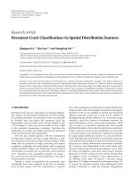
Figure 1: Main modules in context of the GEO unit.
t
x
t
y
P
0
P
1
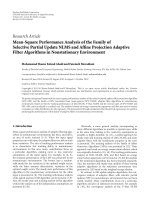
Figure 2: Single parameter set for the GEO unit. t
x
, t
y
, P
0
,andP
1
are 8-bit quantities. So a parameter set fits into a 32-bit data word.
Figure 1 shows the main modules which are involved in
image processing with the GEO unit. The GEO unit has two
interfaces: a streaming data interface (SDI) and a configura-
tion interface (CI). The SDI is connected to a read port of a
multiport memory interface [3]. The multiport memory in-
terface provides some write ports and some read ports which
enable concurrent data transfer between FPGA processing
units and the external memory. To support high speed data
transfer, the SDI of the GEO unit has a data width of 128 bit.
The configuration interface is connected to an on-chip cen-
tral processing unit (CPU) providing the CPU with access to
four types of GEO unit registers: (i) parameter registers, (ii)
command registers, (iii) status registers, and (iv) result reg-
isters. The parameter registers are used for parameterization
of the GEO unit. Different operation modes can be selected
through the command registers, which are also used to actu-
ally start the processing. When processing is started, the CPU
can either poll the appropriate status register to detect com-
pletion of processing, or the GEO unit can be programmed
to notify the CPU by assertion of a dedicated interrupt signal.
After completion, the CPU can read processing results from
the result registers.
The GEO unit features backward transformation and in-
terpolation of the arbit rarily formed image regions. In this
context, a region is defined as a set of points. Therefore,
a specific region is described by a list of (target) points
T
={T
1
, , T
r
} belonging to it. In addition, for every point
T
i
associated parameters (P
0
, P
1
) can be defined, which are
stored together with the points’ coordinates (t
x
, t
y
) in the so-
called parameter set (refer to Figure 2). For example, to rep-
resent a fully filled, that is, there are no “holes,” rectangular
region w ith a width of 4 pixels and a height of 7 pixels, 28
parameter sets are necessary.
As the GEO unit processes parameter sets, there is no
discrimination depending on region shape, that is, any re-
gion shape can be defined this way. Hence, processing time
Johannes F
¨
urtler et al. 3
Interpolation
S
1
S
2
S
3
S
4
S
y
S
x
Source image Target image
Backward
transformation
T
1
T
2
T
3
T
4
t
y
t
x
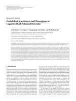
Figure 3: Backward warping and interpolation.
From multiport
memory
Feature data interface
Address
generation
Interpolation
Offset, gain, saturate
Result accumulation
Source memory
256
256
(64 Kbyte)
Parameter
memory
128 parameter
sets
Control unit
Command
Status
Parameter
Result
Register file
Configuration interface
On-chip
CPU
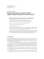
Figure 4: Block diagram of the GEO unit.
is related only to the number of points (r) constituting the
region. The major advantage of this approach is the possibil-
ity to process relevant pixels only, leaving other parts of an
image untouched. This offers a great potential for sp eed up
of algorithms.
Figure 3 shows the relationship between target coordi-
nates and source coordinates determined by the transforma-
tion given by
s
x
= C
02
· t
x
+ C
01
· t
y
+ C
00
,
s
y
= C
12
· t
x
+ C
11
· t
y
+ C
10
,
(1)
where (s
x
, s
y
) are the source coordinates, (t
x
, t
y
) are the target
coordinates, and the C
ij
are constants defining the transfor-
mation.
For the GEO unit, the target coordinates are integer val-
ues. Therefore, they exactly match a pixel position in the tar-
get coordinate system. Generally, the source coordinates re-
sulting from (1) do not exactly match pixel positions. Thus,
the actual gray value v ( T
i
) of a pixel with coordinates (t
x
, t
y
)
is linearly interpolated between the four neighboring pixels.
For example, the gray value of pixel T
1
shown in Figure 3 has
to be interpolated between the highlighted pixels around S
1
.
Figure 4 shows a detailed block diagram of the GEO unit.
The GEO unit features two internal memories: (i) the source
memory and (ii) the parameter memory. The actual image
tile is loaded into the source memory, whereas the point list
is loaded into the parameter memory. Hence, lower mem-
ory bandwidth is required if the same point list, or the same
source tile can be used for several GEO unit operations. For
computation of the source address according (1), the address
generation module uses the parameters C
ij
and the target co-
ordinates from the parameter memory. The C
ij
are specified
by corresponding parameter registers (COEFF00, COEFF01,
and so on). T he four neighboring pixels addressed by (s
x
, s
y
)
are fed into the inter polation module where v(T
i
)iseval-
uated. If (s
x
, s
y
) is outside the source memory, v(T
i
)isre-
placed by a blanking value (BLANKING parameter register).
Processing rate of the address generation and interpolation
is one transformation per clock cycle. Therefore, with every
4 EURASIP Journal on Embedded Systems
clock a new pixel value is fed into the subsequent process-
ing stages. These stages can also use the corresponding pa-
rameters (P
0
, P
1
) for calculations. For example, in Figure 4 a
processing stage is shown where v(T
i
) can be modified by a
multiplicative gain (GAIN) and an additive offset (OFFSET).
The result v
(T
i
) is saturated to 8-bit pixel values before it is
fed into the result accumulation module. Other processing
stages can be added to support implementation of specific
image processing algorithms. In the current implementation,
three results (SUMT, SUMTT,andSUMTP0)arecalculatedin
the accumulation module:
Sum T
=
r
i=1
v
T
i
,
Sum TT
=
r
i=1
v
T
i
2
,
Sum TP
0
=
r
i=1
v
T
i
· P
0
(i).
(2)
The results can be read from the CPU and they can be cleared
by command. So it is possible to a ccumulate results over mul-
tiple processing runs of the GEO unit.
3. APPLICATION OF THE GEOMETRY UNIT FOR
TIE-POINT SEARCH
Localization of typical patters (templates) within an image
is a common (sub)task for many embedded vision systems.
Hence, there is a wide range of approaches which cover the
field of feature tracking [6]. A usual method is normalized
cross-correlation (NCC) [7, 8]. Due to the computational
cost of spatial domain convolution, there is a need of reduced
cost correlation algorithms. The point correlation approach
uses only a carefully selected subset of template points for
the correlation [9, 10]. Therefore, the computational cost is
essentially reduced. In addition, the point correlation can be
combined with search in image pyramids (refer to [11]), re-
fining the search area from higher levels to lower levels of the
pyramid. Point correlation in image pyramids is a very fast
method for tie-point search and it enables very robust but
computational costly character recognition [12]. Therefore,
it is a reasonable choice for applications in industrial print
inspection systems [3, 13]. This section shows how the GEO
unit is used for efficient tie-point search implemented on an
FPGA.
3.1. Algorithm for tie-point search
For example, postal stamps are produced in a complex print-
ing process resulting in sheets containing 100 stamps and
more, possibly with different motifs and arbitrary layout of
the stamps on the sheet. The quality inspection of the print-
ing process requires that the exact position of each stamp
has to be determined [13]. This alone enables comparison of
pixels with their corresponding values on a reference stamp
(training set). Practically, the stamp image can be appropri-
ately rectified by a different affine transformation for every
1
1
(a)
1
1
2
2
(b)
1
1
2
2
3
3
(c)
Figure 5: (a) Rectification of a translation with one tie-point. (b)
Rectification of rotation and scaling with two tie-points. (c) Rectifi-
cation of a general linear deformation with three tie-points.
stamp on the sheet. To determine the parameters of the trans-
formation tie-points are used. A tie-point is a pattern repre-
sented by a small reg ion of the stamp image. Its position acts
as a point of reference. Due to the production process, the ex-
act position of this pattern varies from stamp to stamp. The
number of tie-points determines which kind of image defor-
mation can be rectified (see Figure 5).
In practical applications, the total number of tie-points
can be very high (several hundred). Therefore, tie-point
search is a determining factor for overall processing speed.
The GEO unit enables a very fast search based on point cor-
relation in different image pyramid levels.
Point correlation means that, instead of all pixels of the
template, only few distinctive points are used. For instance,
we reduce from the original template size of 1600 pixels to
n
= 48 points. So the template consists of a point set P =
{
P
1
, , P
n
} only, instead of all template pixels. These points
are prepared in advance and are not selected at runtime. P is
searched for in the actual image, for instance, in a rectangu-
lar search area Σ
={(s, t) | s =−S, , S; t =−T, , T}.
The best matching position is determined by means of nor-
malized cross-correlation as presented in [8], which has been
modified for point lists. Therefore, a tie-point is defined as
the position (s, t), where the coefficient NCC(P, I, s, t), given
by
NCC(P, I, s, t)
=
n
i
=1
v
P
i
I
x
P
i
+ s, y
P
i
+ t
n
i
=1
v
2
P
i
n
i
=1
I
2
x
P
i
+ s, y
P
i
+ t
,
(3)
Johannes F
¨
urtler et al. 5
(a) (b) (c)
Figure 6: Typical point sets and search areas in different pyramid levels. (a) Level G2. (b) Level G1. (c) Level G0.
between P and image I(·, ·) has its maximum value. The
quantities v(
·) are the gray values of the points from P,
whereas x(
·)andy(·) denote their coordinates, respectively.
The image I(
·, ·) is represented as a two-dimensional func-
tion, which results in a gray value for every pair of coordi-
nates.
For every pyramid level, a distinct set of points is pre-
pared, which is shown in Figure 6 for the three levels G0
(highest resolution) to G2 (lowest resolution). To reduce the
number of matching positions, the first search takes place in
the pixel grid of the G2 image. Here, the pixel size is greater
and thus the matching raster is coarser. Accepting a loss of
accuracy at this stage, we are able to scan the same area with
a reduced number of positions. The result is then passed on
to the G1 image, where accuracy is further increased. The ex-
act position is determined in the G0 image. Here, the exam-
ined area and the distance between the examined positions
are gradually refined. Starting w ith an area which is 3
× 3
pixels with a space of one pixel in between, the distance is
then reduced to 1/2and1/4downto1/8 of a pixel. The posi-
tion determined as the best in one step is taken as the center
position for the next step. Finally, the position is determined
with accuracy of 1/8 of a pixel.
3.2. Using the geometry unit for tie-point search
The algorithm for tie-point search can be effectively imple-
mented on an FPGA by use of the GEO unit in conjunction
with the on-chip CPU. Figure 7 shows the flowchart for a
program which runs on the CPU. As prerequisite the point
lists used for point correlation in different pyramid levels
have to be stored in the external memory (refer to Figure 1).
The GEO unit will load these lists into its parameter mem-
ory during processing. The pyramid images can be generated
in par a llel and are also stored in the external memory. Dur-
ing the tie-point search, appropriate parts (tiles) of the pyra-
mid images are loaded into the source memory of the GEO
unit. While there is a new image pyramid for every sheet pro-
cessed, the point lists do not change because they are deter-
mined solely by the reference template.
First, the G2 source tile is loaded and the first search vec-
tor is being processed. A search vector refers to a position
(s, t) within the search area. For every search vector it is de-
termined if the correlation coefficient from (3) is better than
the coefficient for the best position (s
best
, t
best
)sofar.Substi-
Setup pyramid level
Load source memory
Setup search step
Setup search position
GEO operation
Best position?
Update best position
Last position?
Last step?
Last level?
Figure 7: Flowchart for the tie-point search with the GEO unit
(point-correlation in multiple image pyramid levels).
tuting
Sum PI(s, t)
=
n
i=1
v
P
i
I
x
P
i
+ s, y
P
i
+ t
,
Sum II(s, t)
=
n
i=1
I
2
x
P
i
+ s, y
P
i
+ t
(4)
6 EURASIP Journal on Embedded Systems
in (3), then the inequality
NCC(P, I, s, t) > NCC
P, I, s
best
, t
best
(5)
for determination of (s
best
, t
best
)canberewrittenas
Sum PI
2
(s, t) · Sum II
s
best
, t
best
> Sum PI
2
s
best
, t
best
· Sum II(s, t).
(6)
If (6) is true then the best position is updated (s
best
:= s and
t
best
:= t). Sum II(s, t)andSumPI (s, t) are calculated during
processing of the GEO unit (SumTT and SumTP0 registers).
(6) is computed by the CPU—notice that the square root in
(3) has been eliminated in (6).
After processing of all search vectors in G2, the best posi-
tion is used as the starting point for search in G1. In the same
fashion, the best G1 position serves as the starting point for
the search in G0 which results in a pixel accuracy for the tie-
point position. For a more accurate result, the search is fur-
ther refined into some subpixel search steps. For these search
steps only the affine transformation parameters have to be
changed accordingly.
In the actual implementation of the program suggested
by Figure 7, the CPU executes setup and update tasks in par-
allel to the processing of the GEO unit. Therefore, maximum
utilization of the GEO unit is achieved.
4. RESULTS
So far, the GEO unit has been used for an image processing
system based on Altera Stratix
TM
FPGA devices [3]operat-
ing at 133 MHz system clock. In this system, two instances of
the GEO unit have been implemented. One unit is used for
tie-point search, the other one is utilized with calculation of
statistics and dedicated image processing tasks in the field of
quality inspection. This example shows that the universal ap-
proach of the GEO enables design reuse which shortens the
development cycle and, as well, can reduce system costs.
The GEO unit has been implemented using VHDL (very
high-speed integrated circuits hardware description lan-
guage) and is therefore independent from the target technol-
ogy, for example, FPGA or application specific integrated cir-
cuit (ASIC). However, an implementation for FPGAs which
features fast system clock and reasonable resource usage re-
quires optimization depending on the resources available
on the target technology. Therefore, the first VHDL imple-
mentation was tailored for memory blocks and DSP blocks
available on the Stratix device. In addition, other intellec-
tual property (IP) cores supplied by Altera (Nios
TM
soft core
CPU, DDR-SDRAM controller [14]) are used (see Figure 1).
These modules have to be adapted according to the under-
lying technology. Table 1 summarizes the resource usage and
systemclockachievedforStratixdevicesandforStratixII
devices [15, 16]. As expected, the results for the memory
blocks and DSP blocks do not differ due to the same archi-
tecture of these blocks in Stratix and Stratix II. However, the
change in the logic array block structure from logic elements
(LE) based on 4-input look-up tables to adaptive logic mod-
ules (ALM) leads to a better logic density as there are two
Table 1: Implementation results for the Stratix and the Stratix II
devices (Synplify
TM
Pro 8.5, Quartus II
TM
5.1).
Device family Stratix Stratix II
Part EP1S60F1020C5 EP2S60FC1020C3
M4K Memory (4 kBit)
88
MRAM (64 kByte)
11
9-bit multiplier
44
18-bit multiplier
11
Two 18-bit multiply
accumulate
22
Four 9-bit multiply
accumulate
11
Logic elements used 2527 (LEs) 2224 (ALUTs)
System clock
174 MHz 240 MHz
Table 2: Implementation results for the Virtex-II and the Virtex-4
devices (Synplify
TM
Pro 8.5, ISE 8.1).
Device Virtex 2 Virtex 4
Part XC2V1000-6FF896 XC4VSX55-10FF1148
4 input LUTs
3315 2297
RAM blocks (16 kBit)
36 36
Mult 18
× 18 6—
DSP48s
—12
Table 3: Processing performance for the tie-point search algorithm
implemented on different platforms.
Platform System clock [MHz] Processing time [μs]
GEO Unit 133/100 90
C62x
250 250
C64x
1000 90
Pentium 4
3200 100
adaptive look-up tables (ALUT) available per ALM. More-
over, the new FPGA generation enables substantially higher
system clocks (plus 40%).
In order to evaluate the feasibility of the approach on
different FPGA architectures, the GEO unit has been imple-
mented on Xilinx Virtex-II devices and on Virtex-4 devices
[17, 18]. Table 2 shows that the Xilinx design needs a little bit
more memory for the parameter memory than the Altera de-
sign. The reason is the size of the parameter memory, which
has the dimension 4
× 32 bit with 256 words. For the Xilinx
implementation, this memory cannot be mapped into two
RAM blocks of the Virtex architecture. The data bus width
is 128 bit, therefore, four RAM blocks are needed instead of
two.
Tab le 3 summarizes performance results for the tie-point
search (see Chapter 3) measured for typical tie-point pa-
rameters: G2/32/49/1, G1/40/25/1, G0/48/9/4 (pyramid level,
number of points, number of search vectors, number of
search steps). The system clock for the GEO unit is 133 MHz
and 100 MHz for the Nios CPU. Despite the fact that the
FPGA implementation is running at the slowest clock speed,
the overall processing performance is slightly better than
Johannes F
¨
urtler et al. 7
achieved with implementations optimized for the C6x
TM
DSPs from Texas Instruments (refer to [19]) and the Intel
Pentium
TM
4. The better performance is due to the pipelined
operation of the GEO unit, where a new result is computed
in every clock cycle. Moreover, on the FPGA, additional pro-
cessing units can be implemented, for example, a second
GEO unit, which results in even better performance ratios
compared to the DSP implementation.
For the particular example, 4296 points have to be evalu-
ated (backward transformation, interpolation, modification,
and accumulation). Hence, not considering overheads, the
total time for geometry operations is just above 32 μs. The
time for loading the source tiles and the parameters accounts
for additional 10 μs. Therefore, up to 50% of the processing
time is spent for code execution on the Nios CPU. The tie-
point search focuses on relatively short point lists (contribut-
ing a third to the total processing time) and requires many
CPU interactions. The GEO unit performance can be tuned
for this case by improving the execution speed of the pro-
gram, for example, by implementing portions of the code in
assembler or by introducing special hardware support. How-
ever, for algorithms needing processing of longer lists, for ex-
ample, image statistics, the influence of the CPU can be ne-
glected.
5. CONCLUSIONS AND FURTHER WORK
The geometry unit proposed in this paper represents a uni-
versal building block for system on chip architectures. The
universality results from the flexible combination of the ge-
ometry unit and an on-chip CPU. The suggested distribu-
tion of work load to these two units enables easy adapta-
tion for different needs. Practical experience has shown that
this approach can be successfully used for various applica-
tions in image processing. In this paper, the suitability for
fast tie-point search in image pyramids has been presented.
As the geometry uses point lists for its operation, templates
can have arbitrary shape which does not influence process-
ing time. Other applications include, among others, arbitrary
projections, statistical measurements over arbitrar y regions,
and optical character recognition.
Future enhancements may address several of the follow-
ing issues.
(i) As the proposed method is very fast, several disadvan-
tages of the normalized cross-correlation can be reduced: to
cover rotations and different sizes of the image, the dimen-
sion of the search space can be extended. Consequently, ad-
ditional iterations have to be introduced. However, only the
transformation parameters have to be changed appropriately
by the CPU, no changes to the GEO unit are necessary.
(ii) Currently an affine backward transformation is im-
plemented. Higher order transformation can be of interest
for some applications, for example, to rectify perspectival de-
formations as they appear in images of cylindrical objects.
(iii) The geometry unit processes one pixel per clock cy-
cle. Parallel processing of two or more pixels will substan-
tially improve performance. For this reason, the data width
for storing a pixel has to be increased. Currently, a pixel is de-
fined as an 8-bit quantity. Especially, for processing of color
images, a pixel is defined by several parameters within a color
space,forexample,red,green,andblue.Hence,pixelrepre-
sentation has to be changed, for example, to a 24-bit quan-
tity. On the other hand, for better resolution, 10 or 12 bits are
desirable even for gray-level images.
(iv) There are applications where the coordinates of the
point lists remain the same during several processing itera-
tions, however, the parameters are changed for each iteration.
As coordinates and parameters are stored together, the coor-
dinates are loaded redundantly. Separating these memories
will reduce memory usage and memory bandwidth require-
ments.
(v) For some tasks, the coordinates of the pixel lists have
a predefined shape, for example, rectangular area, line from
point A to point B, and circular arcs. An address generator
which can automatically compute these coordinates accord-
ing to some para meters (start point, width, height, and so
on) eliminates the need for loading such lists from memory.
(vi) The Euclidian coordinate system can be replaced by
polar coordinates. This can be especially helpful for applica-
tions where circular object have to be investigated, for exam-
ple, coins [20].
REFERENCES
[1] P. R
¨
ossler, C. Eckel, H. Nachtnebel, J. F
¨
urtler, and G. Cadek,
“FPGA-Design f
¨
ur ein Hochleistungs-bildverarbeitungssys-
tem,” in Proceedings of the Austrian National Conference on Mi-
croelectronics (Austrochip ’04), pp. 83–88, Villach, Austria, Oc-
tober 2004.
[2] J. F
¨
urtler,J.Brodersen,P.R
¨
ossler, et al., “Architecture for hard-
ware driven image inspection based on FPGAs,” in Real-Time
Image Processing, vol. 6063 of Proceedings of SPIE, pp. 105–113,
San Jose, Calif, USA, January 2006.
[3] J. F
¨
urtler, P. R
¨
ossler, J. Brodersen, et al., “Design considerations
for scalable high-performance vision systems embedded in in-
dustrial print inspection machines,” to appear in EURASIP
Journal on Embedded Systems.
[4] Z. Salcic and A. Smailagic, Digital Systems Design and Proto-
typing Using Field Programmable Logic and Hardware Descrip-
tion Languages, Kluwer Academic, Boston, Mass, USA, 2000.
[5]E.R.Davies,Machine Vision, Morgan Kaufmann, San Fran-
cisco, Calif, USA, 2005.
[6] H. Penz, I. Bajla, K. J. Mayer, and W. Krattenthaler, “High-
speed template matching with point correlation in image
pyramids,” in Diagnostic Imaging Technologies and Industrial
Applications, vol. 3827 of Proceedings of SPIE, pp. 85–94, Mu-
nich, Germany, June 1999.
[7] J. P. Lewis, “Fast normalized cross-correlation,” in Vision I n-
terface, pp. 120–123, Quebec, Canada, June 1995.
[8] P. Aschwanden and W. Guggenb
¨
uhl, “Experimental results
from a comparative study on correlation-type regi ion algo-
rithms,” in Robust Computer Vision: Quality of Vision Algo-
rithms,W.F
¨
orstner and S. Ruwiedel, Eds., pp. 268–289, Wich-
mann, Karlsruhe, Germany, 1992.
[9] W. Krattenthaler and K. J. Mayer, “Point correlation: a
reduced-cost template matching technique,” in Proceedings
of the 1st IEEE International Conference on Image Processing
(ICIP ’94), vol. 1, pp. 208–212, Austin, Tex, USA, November
1994.
8 EURASIP Journal on Embedded Systems
[10] W. Krattenthaler and K. J. Mayer, “Point correlation: a new
approach for high-speed template matching,” in Proceedings
of DAG M/O AGM Conference, pp. 642–649, Vienna, Austria,
September 1994.
[11] B. J
¨
ahne, Digital Image Processing,Springer,NewYork,NY,
USA, 1991.
[12] H.Penz,I.Bajla,A.Vrabl,W.Krattenthaler,andK.J.Mayer,
“Fast real-time recognition and quality inspection of printed
characters via point-correlation,” in Real-Time Imaging V,
vol. 4303 of Proceedings of SPIE, pp. 127–137, San Jose, Calif,
USA, January 2001.
[13] J. F
¨
urtler,W.Krattenthaler,K.J.Mayer,H.Penz,andA.Vrabl,
“SIS-Stamp: an integrated inspection system for sheet prints
in stamp printing application,” Computers in Industry, vol. 56,
no. 8-9, pp. 958–974, 2005.
[14] “DDR SDRAM Controller MegaCore Function User Guide,”
document version 1.2.0 rev 1, Altera, San Jose, Calif, USA,
March 2003.
[15] “Stratix Device Handbook,” S5V1-3.1 and S5V2-3.1, Altera,
San Jose, Calif, USA.
[16] “Stratix II Device Handbook,” SII5v1-3.1 and SII5v2-3.1, Al-
tera,SanJose,Calif,USA.
[17] “Virtex-II Platform FPGAs: Complete Datasheet,” DS 031
(v3.4),Xilinx,SanJose,Calif,USA.
[18] “Virtex-4 User Guide,” UG 07 (v1.5) and UG073 (v2.1), Xilinx,
San Jose, Calif, USA.
[19] J. F
¨
urtler,K.J.Mayer,W.Krattenthaler,andI.Bajla,“SPOT—
development tool for software pipeline optimization for
VLIW-DSPs used in real-time image processing,” Real-Time
Imaging, vol. 9, no. 6, pp. 387–399, 2003.
[20] M. N
¨
olle, H. Penz, M. Rubik, K. J. Mayer, I. Holl
¨
ander, and
R. Granec, “Dagobert—a new coin recognition and sort-
ing system,” in Proceedings of the 7th International Confer-
ence on Digital Image Computing—Techniques and Applica-
tions (DICTA ’03), vol. 1, pp. 329–338, Sydney, Australia, De-
cember 2003.