Báo cáo hóa học: " Using Simulated Partial Dynamic Run-Time Reconfiguration to Share Embedded FPGA Compute and Power Resources across a Swarm of Unpiloted Airborne Vehicles" pdf
Bạn đang xem bản rút gọn của tài liệu. Xem và tải ngay bản đầy đủ của tài liệu tại đây (6.4 MB, 12 trang )
Hindawi Publishing Corporation
EURASIP Journal on Embedded Systems
Volume 2007, Article ID 48521, Pages 1–12
DOI 10.1155/ES/2007/48521
Using Simulated Partial Dynamic Run-Time Reconfiguration
to Share Embedded FPGA Compute and Power Resources
across a Swarm of Unpiloted Airborne Vehicles
David Kearney and Mark Jasiunas
Reconfigurable Computing Laboratory, School of Computer and Information Science, University of South Australia,
Mawson Lakes Boulevard, Mawson Lakes, South Australia 5095, Australia
Received 19 May 2006; Revised 1 November 2006; Accepted 1 November 2006
Recommended for Publication by Neil Bergmann
We show how the limited electrical power and FPGA compute resources available in a swarm of small UAVs can be shared by
moving FPGA tasks from one UAV to another. A software and hardware infrastructure that supports the mobility of embedded
FPGA applications on a single FPGA chip and across a group of networked FPGA chips is an integral part of the work described
here. It is shown how to allocate a single FPGA’s resources at run time and to share a single device through the use of application
checkpointing, a memory controller, and an on-chip run-time reconfigurable network. A prototype distributed operating system
is described for managing mobile applications across the swarm based on the contents of a fuzzy rule base. It can move applications
between UAVs in order to equalize power use or to enable the continuous replenishment of fully fueled planes into the swarm.
Copyright © 2007 D. Kearney and M. Jasiunas. This is an open access article distributed under the Creative Commons Attribution
License, which permits unrestricted use, distribution, and reproduction in any medium, provided the original work is properly
cited.
1. INTRODUCTION
The term swarm is usually identified with a group of living
organisms who arrange themselves to cooperate to achieve a
common task that no one of them could complete as an indi-
vidual. For example, a swarm of birds may fly in a slipstream
formation to save on energy or a swarm of ants will con-
struct a shortest spanning tree path between a food source
and their nest [1]. UAVs that cooperate to achieve a com-
mon task (such as geolocation) in an autonomous way (us-
ing agents) have been given by analogy the title of swarm in
this paper.
Small UAVs (of weight less than 25 kg and wingspan less
than 3 m) are often limited by their resources as compared
with larger manned and unmanned planes. For example,
some small UAVs rely on battery power for both the engine
and electronics whilst others use conventional internal com-
bustion engines with battery/generator system that allows
energy conversion from fuel to electricity but small UAVs
only require modest fuel inputs to maintain level flight and
thus the power requirements of the computing resources can
still consume a substantial amount of the available energy
and reduce the range and endurance time of the plane.
In this paper, we introduce the concepts of sharing a sin-
gle FPGA among different tasks that may not need to exe-
cute at the same time and allowing such tasks to migrate be-
tween members of the swarm either to share power across
the swarm or provide for the replacement of members of the
swarm who may need refuelling without stopping the execu-
tion of tasks critical to the swarms mission.
The paper is organized as follows. In Section 2,were-
view the literature on capabilities and applications of small
UAVs and the compute platforms they might use. We ex-
amine publications that report the benefits swarms of UAVs.
We show that whilst there have been many publications of
swarm applications, there has been less attention to the re-
source sharing possibilities of swarms especially extensions
to compute sharing and power sharing. In Section 3, we in-
troduce a typical scenario where power and FPGA computer
resource shar ing could be beneficial in a swarm of UAVs per-
forming a surveillance function.
Section 4 presents work showing how a single FPGA can
be shared amongst several compute tasks that are relevant to
UAV applications. This is the first time an operating system
for reconfigurable computing has been implemented to exe-
cute practical embedded a pplications.
2 EURASIP Journal on Embedded Systems
Section 5 introduces infrastructure for mobility of appli-
cations between UAVs. We explain w hy we have opted for
agent-based decentralized control of mobility and fuzzy rules
for the decision making. We describe check pointing of ap-
plications.
2. PREVIOUS WORK AND REVIEW OF LITERATURE
The review of literature first discusses the capabilities of and
applications to which small UAVs have been applied. We
describe the computing requirements for a small UAV per-
forming these applications. We show from the literature that
scarce resources for small UAVs include electrical power and
high-perfor mance computing capability. We give examples
from the literature that show how power can be minimized
and computing capability maximized on a single UAV by the
use of FPGAs on UAVs in preference to more traditional soft-
ware only embedded systems.
Next we investigate the advantages that a swarm of UAVs
has over single platforms in overcoming small UAV limita-
tions. We give examples of how a swarm can improve appli-
cation performance in geolocation by using the diversity of
sensor locations. We highlight that there is no literature of
the use of a swarm to share the scarce resources that support
these types of applications. In particular, there has been no
investigation of the sharing of power and high-perform ance
embedded computing resources across the swarm.
Next we review the literature on the sharing of the types
of embedded FPGA compute resources that are used on small
UAVs. Using our definition of partial dynamic run-time re-
configuration, we show how published operating systems for
reconfigurable computing might allow the sharing of FPGA
resources among many applications in UAVs applications.
We note that the literature does not contain specific work on
the extension of FPGA application sharing in a distributed
sense across several FPGAs. These topics are the subject of
this paper.
2.1. Capabilities and applications of single small UAVs
In this section, we describe how small UAVs have been used
in civilian and defence roles. We illustrate both the advan-
tages and limitations of small UAVs working alone.
Unmanned airborne vehicles are projected to become a
major segment of the aviation industry over the next 20 years
[2], pr imarily enabled by developments in computing, com-
munications, and sensor technologies. An area where UAVs
will likely make a major impact is in surveillance and re-
mote data collection. Examples of applications include fire
ground (active bushfire) surveillance, crop and vegetation
surveying [3], emergency data communications and main-
taining the security of people, and assets against terrorist-
related threats [4].SmallUAVs(ofgrossmasslessthan
25 kg) will most likely perform these tasks, working together
in closely co-located teams called swarms. This is because
swarms can carry a range of sensors, and their diversity over-
comes the limited field of view of a single small UAV flying at
a relatively low altitude. Swarms also provide increased relia-
bility through redundancy.
The sensors used on small UAVs have in the past been
confined to very light-weight devices. For example, video
camerasandsmallRFsensorsarequitepracticalonsmall
UAVs. However, it is clear from studies conducted on large
UA Vs [5] and satellites that more complex sensors such as
infrared imagers could provide a major improvement in the
quality of information that can be gathered [6].
The 2002 NASA project used the solar power pathfinder
UAV to demonstrate crop monitoring over the coffee plan-
tations in Hawaii [3]. This UAV is capable of extremely long
loitering times which were used to map weed invasions as
well as irrigation and fertilization irregularities. This project
also demonstrated how UAVs can plan flight paths to avoid
obstructed view of the ground by cloud cover. NASA has also
used APV-3 UAVs to survey vineyards in Monterey Califor-
nia where up to $12.5 million in produce is lost annually due
to frost damage [7]. The UAV collected hyper-spectral im-
agery which was relayed to ground stations where data was
combined with information gathered from ground sensors.
2.2. FPGAs as compute platforms for small UAVs
A reconfigurable computer is a processing platform consist-
ing of a general purpose processor interfaced to memory
and a programmable logic device PLD [8]. The most widely
used PLD is a field programmable gate array (FPGA) [9]. An
FPGA is an array of logic cells connected via programmable
routing. Each logic cell can be configured to perform logic
functions allowing complex circuits to be constructed. FP-
GAs are ideal for implementing common types of algorithms
on UAVs [10–14].
Sharing an FPGA amongst several applications dynami-
cally is a relatively new concept in the reconfigurable com-
puting field. This was first proposed by Wigley and Kear-
ney [15] who defined the basic required components, be-
ing allocation, partitioning, placement, and routing. Alloca-
tion, partitioning and placement algorithms have been fur-
ther explored in [16–18], and routing and on-chip networks
in [19, 20].
2.3. Advantages of swarms of UAVs
In this section, we describe the advantages of small UAVs. It is
shown using example applications how swar ms can increase
the capabilities of such UAVs.
Small inexpensive UAVs have been found useful in mil-
itary roles. They can be considered somewhat expendable,
allowing swarms to oper ate in closer proximity to threats
where sensors and effectorsaremoreeffective and operate
using less power [21]. One such area of research is electronic
warfare where the goal is to gather information and suppress
the enemy’s information gathering using electronic sensors
and effectors (jamming). For example, several UAVs can be
used to geolocate the position of radar emitters for suppres-
sion [22]. A UAV can fly much closer to a radar emitter mak-
ing jamming possible at very low power. While the prospect
D. Kearney and M. Jasiunas 3
of armed UAVs in combat roles has been explored, the cur-
rent focus remains on intelligence, surveillance, and recon-
naissance missions [23].
Geolocation is a good example of the benefits of swarms.
It requires the cooperation and exchange of information be-
tween several UAVs. Geo-location works by taking a direc-
tional bearing of an object from a number of different lo-
cations and combining them to determine the objects’ exact
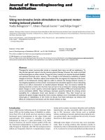
position. Finn et al. describe how a group of 6 sensors can
reduce the location error by more than 80% (Figure 1)[21].
2.4. Sharing resources in a swarm: a typical scenario
The missions of UAV swarms can be divided into two classes.
In the sing le mission, we have a swarm requiring N planes
each with different capabilities to perfor m the swarm func-
tion. We have just N planes available. We deploy these planes
and attempt to arrange their computing tasks so that all
planes run out of fuel at the same time. Allowing for fuel to
return to base (assumed the same for each plane) we end the
deployment when each plane has just this much fuel left. The
aim is to maximize the time that the swarm is deployed over
the target area doing useful work.
In the continuous mission scenario N planes are required
to form the swarm but we assume that we have N +1 or more
planes available. Thus it is possible to maintain a continuous
mission by retiring planes from the swarm that are running
low on fuel and replacing them with other planes with a full
fuel load. The objective in this case is for example to maintain
continuous surveillance over the target area. Task mobility is
essential in the continuous mission scenario. In the following
we describe why this is the case.
If the computing tasks that the swarm must execute are
stateful applications like tracking [6] the continuous mission
is only feasible if task state can be migrated from the mem-
bers of the swarm that are running low on fuel to those that
are replacing them. Thus task mobility is required for this
type of mission to be feasible. In the single mission case task
mobility is not str ictly necessary for feasibility. Tasks can be
loaded on each member of the swarm. The swarm will then
remain aloft till the first plane in the swarm losses power.
Then the whole swarm must return to base. It might seem
possible therefore to plan so that each plane has exactly the
fuel loaded for the tasks needed to perform if you know in
advance the workload that the swarm will encounter. How-
ever, we do not know in advance the workload of the swarm
in many practical situations. For example, imagine that the
task of the swarm is to perform surveillance. This applica-
tion consists of a continuous task of scanning the seas below.
UAV1 looks for an objec t using a low power visible CMOS
camera. When the object is identified, then a high power pe-
riodic task is invoked to gain an alternative image of the ob-
ject using an IR sensor on UAV2. The relative power con-
sumption depends on how often the IR sensor is used during
the mission. Because we cannot predict how many objects
will be detected on the mission, we cannot predict the rel-
ative power consumption between the UAV1 and UAV2 due
to the difference in the power required to operate the sensors.
2 4 6 8 10 12 14 16 18 20 22 24 26 28 30
Number of receivers
Relative accuracy
0
0.2
0.4
0.6
0.8
1
1.2
1.4
1.6
1.8
Figure 1: Reduction in the location error margin (Y -axis) with the
number of sensors (X-axis) used to determine the location [21].
Thus in the absence of task mobility it could be expected that
one UAV would run of power sooner than the other. If we
have task mobility, then we can equalize the power between
the UAVs.
2.5. Agents mobility and mobile agents
The question now arises as to how we can arrange for
this mobility to happen. We have decided to use the agent
paradigm to express and control this mobility. It is generally
accepted that an agent must posses at a minimum the prop-
erties of autonomy, social interaction, reactivity,andproac-
tiveness [24]. Mobile agents are a special class of agents that
are able to migrate between host computer systems while ex-
ecution [25]. Mobile agents are not able to function without
the support of an agent environment that executes on host
systems and aids in the migration process. In the remainder
of this section, the key properties of agents are examined in
greater detail.
The autonomous operation of agents in dynamic systems
are one of their most attractive features. An autonomous
agent is entrusted to act and decide on courses of action with-
out being specifically directed by the user [26]. This ability of
agents is especially useful in dynamic environments where
deterministic processes or agents would require constant in-
struction from the user. Milojicic et al. [27] defines the trans-
fer of authority to act on a user behalf as the defining at-
tribute of mobile agents when compared to other forms of
mobile code and execution.
The agent paradigm implies a degree of interaction be-
tween agents and external entities. Social interactions are im-
plemented by exchanging messages formatted in an agent
communication language [28]. The messages can contain in-
formation or coordination of activities where agents are col-
laborating to achieve common goals. Through teambuild-
ing, individual agents have the ability to increase there ef-
fectiveness by cooperative coordination in order to achieve
4 EURASIP Journal on Embedded Systems
common goals [29]. In agent environments with restricted
resources, selective teambuilding and coordination can max-
imize the usage of resources.
2.6. Conclusion
FPGAs are an appropriate platform for small UAVs because
they have low power requirements yet can compute high
complexity tasks such as image processing. Small UAVs are
best arranged as swarms so that the limited capabilities of
each member of the swarm c an be combined. Once a swarm
is established all members of the swarm need to be present
to perform the task. We have shown that mobility of FPGA
tasks between members of the swarm will allow a swarm to
be active for a longer period of time or allow the continuous
replacement of members of the swarm. The literature survey
shows that there have been no examples of FPGA task mo-
bility and within the context of embedded s ystems for UAVs
there are no examples of the sharing of tasks even on a single
UAV. These topics are the subject of the rest of this paper.
3. SHARING UAV COMPUTING TASKS ON
ASINGLEFPGA
3.1. Introduction
Embedded applications designed for implementation on an
FPGA have traditionally had exclusive use of the resources of
the device. As FPGA devices get bigger it is now feasible to
load many compute tasks onto a single FPGA. In UAV appli-
cations, however, not all tasks need to be active at once. Shar-
ing the resource by not loading tasks till they are needed and
removing them when complete can save power and improve
the overall flexibly of the UAV as a compute platform. In the
scenario defined above, compute tasks can be loaded onto the
FPGA in a sequence that is not known at design time. This
requirement fundamentally changes the way tasks must be
designed because no task will know in advance exactly which
FPGA resources are available when it begins to execute. An
operating system [15] (or run time system) performs these
resource allocations dynamically. Despite the extensive re-
search performed on these systems [30–37], there has been
no demonstration of practical UAV embedded computing
tasks actually being controlled by such a run time system. In
this section, we describe a practical demonstration of an em-
bedded operating system for FPGAs working with tasks rele-
vant to UAVs. Firstly, the basic elements of the operating sys-
tem for embedded FPGAs are described. We then show why
true partial dynamic run time reconfiguration for the prac-
tical tasks needed on a UAV cannot be achieved with current
FPGA hardware. We describe how check pointing of appli-
cations together with caching of whole chip configurations
can overcome most of these limitations. The implementa-
tion of the memory arbitration and run-time reconfigurable
on-chip network required to support practical applications
running under the operating system are then detailed. Com-
pute tasks intended to execute under the operating system
have special requirements (including the ability to be check-
pointed) and these are explained next. Finally, we give details
of the actual tasks that we have demonstrated running under
the operating system.
3.2. Basic elements of an embedded operating
system for FPGAs
This section describes the basic elements of an operating sys-
tem for reconfigurable computing that allows resources to be
shared on a single FPGA and resource allocation decision to
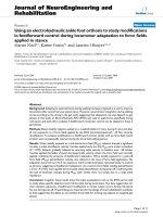
be made at run time. The unique phase of FPGA resource
allocation is area allocation and Figure 2 provides a pictorial
representation of this phase.
When the application is to begin, the circuit is given to
the operating system. The operating system uses precompiled
information about the circuit along with the current state
of the FPGA to write a set of constraints which define what
resources each circuit will be allocated to. These constraints
along with the circuit descriptions are then used to generate a
configuration for the FPGA. Resource allocation algorithms
are required to determine the region of unoccupied resources
that can be used to implement the hardware task. Being able
to place tasks arbitrarily makes best use of the FPGA area
as opposed to tile-based placement which generates internal
fragmentation w hen small tasks are placed within large fixed
tiles.
If the FPGA is considered a rectangular region, and hard-
ware tasks are polygons defining an area which contain the
resources necessary to run a particular task, the allocation
problem can be reduced to a geometric packing problem.
The aim of an allocation algorithm is to place the polygon
tasks into a 2D area as efficiently as possible. The possi-
ble allocation algorithms vary greatly in efficiency, complex-
ity, and functionality. The time critical nature of dynamic
IP core placement means that many allocation algorithms
widely used for offline placement, such as simulated anneal-
ing [38], cannot be used. Some candidates for online allo-
cation algorithms are Best Fit, Bottom Left [39], Bazargan’s
fast template placement [40], and the Minkowski sum [17].
It has been shown that the Minkowski sum is the fastest al-
gorithm in execution and has acceptable perfor mance by not
fragmenting the space on the FPGA.
The Minkowski sum is a useful geometric algorithm
which can identify the perimeter of a region of space where
a task can be successfully placed without interfering with
other t asks. Once the Minkowski sum has been used to iden-
tify the area where a valid placement can be performed,
the bottom-left most position is selected for allocation. The
Minkowski algorithm has two major advantages over virtu-
ally all other allocation algorithms. First is that the algorithm
can correctly allocate nonrectangular cores, whereas other al-
gorithms must place non-rectangular shapes within a rectan-
gle for placement causing further area fragmentation.
Secondly, the algorithm natural ly handles holes in the
free space which are commonly created when tasks end their
execution. Finally, the Minkowski sum is linear in complex-
ity for rectangular polygons, but increases in complexity for
D. Kearney and M. Jasiunas 5
Incoming
application FPGA surface
Figure 2: The allocation phase of an operating system. The incom-
ing application must be placed on the FPGA so it does not contend
with resources of existing applications.
polygons with more edges. The worst case complexity, when
the cores to be placed are nonrectangular and concave, is
O(m
2
n
2
), where m is the number of vertices in the union of
the placed cores and n is the number of vertices of the core to
be placed—nonrectangular concave shapes are not common
in real reconfigurable computing applications.
In this section, we have described the basic operations
performed by an operating system for reconfigurable com-
puting.
3.3. Dynamic partial reconfiguration and real FPGAs
The most general way an FPGA can be reconfigured is de-
noted in this paper as partial dynamic run-time reconfigura-
tion.ThistermisdefinedtomeanthatanFPGAwithtasks
loaded and executed on it can have part of its area reconfig-
ured without necessarily stopping the existing tasks. We note
that whilst there have been publications reporting partial dy-
namic run-time reconfiguration on a limited scale [41], the
current architecture FPGA have numerous constraints which
prevents this operation for practical size circuits. We will now
describe why this is the case.
For the purpose of this discussion, the configuration pro-
cess of the popular Xilinx Virtex family of FPGAs is adopted
as an example, as the configuration of an FPGA is family
dependent. Reconfiguration of Virtex chips is column-based
with frames within each column being able to be reconfig-
ured atomically. T his means that reconfiguration of any part
of a thin vertical column of a chip implies stopping any cir-
cuit that intersects with this column. Whilst one could wait
for circuits to complete current tasks before triggering any re-
configuration operation this would add arbitrary latency to
the start up of any task which is impractical in the real time
applications that are commonly used on UAVs.
In order to be able to reconfigure parts of the FPGA with-
out affecting circuits already executing that are not going to
be reconfigured, the interconnects which communicate to
logic within the area being reconfigured and logic elsewhere
on the chip must be able to be hot swapped using a mech-
anismsuchastristatebuffers or LUT-based macros [42].
Typically the number and location of these types of tristate
buffers severely constrains the way tasks can be configured
on the FPGA. The LUT-based macroapproach implies fixed
tile-based layout which suffers from internal tile fragmenta-
tion since the maximum size of tasks placed is not know in
advance.
The current absence of a practical mechanism allow-
ing partial dynamic run-time reconfigurations of arbitrary-
shaped regions of the device has led us to propose a com-
promise which we call simulated partial dynamic reconfigu-
ration. In this situation, existing applications on the FPGA
are checkpointed and the entire FPGA is reconfigured. Af-
ter new tasks are added and old tasks removed, then all cur-
rently active tasks are started. Because checkpointing is a key
to making simulated partial dynamic reconfiguration possi-
ble, the next section explains how checkpointing is achieved
for practical UAV applications.
3.4. Checkpointing
The consequences of using simulated partial dynamic recon-
figuration to load and remove hardware tasks is that every
resource on the device is reprogrammed with new configura-
tion data and in the process overwr ites all currently executing
tasks. During this process, the state of tasks executing is lost.
A mechanism for preserving state during reconfiguration is
required. We call this process checkpointing of applications.
There are two options for checkpointing. In the first,
which we call cooperative checkpointing, the operating sys-
tem tells tasks that a reconfiguration is required and waits
for all tasks to reach their checkpoints. In the second, which
we call preemptive checkpointing, tasks periodically do their
own checkpointing allowing them to be restarted at that
checkpoint even if reconfiguration is forced at an arbitrary
time.
In cooperative checkpointing, the latency between when
the operating system requests a reconfiguration and when the
last task completes its checkpointing is unbounded and can
not be known in advance. There is a chance that poorly de-
signed tasks may never reach a checkpoint thereby freezing
the operating system. There is an area overhead in coopera-
tive checkpointing because extra circuitry must be provided
to preserve the state of the circuit. For pre-emptive check-
pointing, there is no latency for the operating system in re-
questing a reconfiguration because all tasks can be stopped
immediately; a reconfiguration becomes necessary. There is
also an area overhead in the pre-emptive checkpointing of
applications which is the same as the area used in cooper-
ative checkpointing. It might be imagined that pre-emptive
checkpointing would slow applications down because of the
time overhead of periodic saving of state. However, the peri-
odic saving of state can be executed in parallel in many ap-
plications with the normal computation of the task and thus
this overhead can be minimized. Pre-emptive checkpointing
is easier for application developers to manage because there
is no need to interface to a special reconfiguration interrupt
coming from the operating system. For the reasons listed
above, we have implemented the pre-emptive checkpointing
detailed above. In the next paragraph, we detail how this has
been implemented.
6 EURASIP Journal on Embedded Systems
For pre-emptive checkpointing, the application is de-
composed into groups of logic which represent atomic oper-
ations. These atomic operations then become states in a state
machine. Each time the machine transitions into a new state,
the variables that make up the state of the application are
stored in external memory. The application performs pro-
cessing within a loop. At each iteration this state is updated.
At any point the application can thus be terminated. When
the application resumes execution it will restart from the be-
ginning of the last checkpoint.
We have investigated pre-emptive checkpointing in the
three applications that were implemented in our operating
system. The first application was feature tracking. In this ap-
plication, video scenes are searched for a collection of adja-
cent pixels with common characteristics. If such a collection
of pixels is located, the coordinates are calculated as output.
For this application, checkpointing is not necessary because
there is no state retained between one video frame and the
next. This means that if reconfiguration is initiated in the
middle of a fr ame, the data w ill be lost and the data from the
next available frame will be calculated. The second applica-
tion we investigated was Sobel edge enhancement. In this ap-
plication, a buffer of frames is processed by the algorithm to
generate the output. Checkpointing only requires the record-
ing of which frame is required to be analyzed. If the edge de-
tection of the required frame is interrupted, it is only neces-
sary to go back and recover the input frame from a buffer and
restart the edge detection from this frame. The final applica-
tion we implemented a data encryption algorithm. Check-
pointing this application is similar to Sobel application be-
cause it is only necessary to remember what block was being
processed before processing was interrupted by the recon-
figuration. More complex application such as a correlation
tracker [6] will require more checkpoints as the data is pro-
cessed iteratively to produce the result. In such an applica-
tion, checkpointing after each iteration is required.
3.5. Sharing resources amongst applications
It has just been shown that constraint files and geometric al-
location algorithms can be used to confine the logic resources
of hardware circuits to mutually exclusive regions and that
checkpointing can enable simulated partial dynamic recon-
figuration so that circuits can be swapped on and off an
FPGA. In this section, the interconnection and arbitration
between these logic circuits are considered.
There are three components required for multiple cir-
cuits to access shared external (off-chip) memory; a network,
an arbitrator, and a memory partitioning policy. The net-
work specifies the interface that tasks must connect to in or-
der to communicate with the arbitrator. The network spec-
ifications include both wiring definitions and protocols for
read and write requests. The design of the network itself is
one of the most influential components of the operating sys-
tem as far as performance is concerned, as the design will de-
termine the data throughput between the memory banks and
the processing circuit. The on-chip network connects the ap-
plications to the arbiter which controls the access to memory
and resolves contention. The memory partitioning policy de-
termines how the applications share the available memory.
These components and their implementations are now dis-
cussed.
3.5.1. Memory network
An on-chip network is used to connect the memory arbiter to
the applications. Six network topologies that are candidates
for implementation, bus, star, mesh, ring, tree, and fat tree,
are described by Kearney and Veldman [19]. Each is inves-
tigated for its suitability for implementation specifically for
the UAV swarm environment. In evaluating the topologies,
the following criteria are considered.
Ease of implementation
How difficult is this topology to implement natively on an
FPGA given that the network must be dynamically reconfig-
ured?
Wire routing cost
How expensive is it to route wires to a new application in
the topology? Some topologies require many wires to be r un
over large distances on the chip, which is a very expensive
operation in an FPGA environment.
Concurrency
How well does this topology support concurrency? The
topology should allow, for example, multiple memory banks
that are connected to the FPGA to be accessed simultane-
ously.
Latency
What is the latency and how does it vary as applications join
the network?
Scalability
How does this topology scale for large numbers of applica-
tions? How does the latency or wire routing cost complexity
increase as more applications are added to the network?
Impact on area allocation
The network must work in an environment where cores ar-
rive and must be dynamically placed on the FPGA. How does
the topology constrain the locations possible for a new ap-
plication? Allocation algorithms suggested in [17] favor lo-
cations that minimize the amount of area fragmentation be-
cause fragmented area is not available for new applications.
How will the new network topology interact if we allow the
allocator to favor locations that need shorter and therefore
cheaper routes to the network and reduce the fragmentation
of area to a minimum?
D. Kearney and M. Jasiunas 7
Tabl e 1: Evaluation of network topologies + means favourable −
unfavourable +/− neutral.
East of
implementation
Wire
routing
cost
Concurrency Latency Scalability
Bus ++ −−−−−−
Star ++ −− ++ ++ −−
Mesh −− −− +++
Ring
++ + − +/− +/−
Tree +/− ++ +/− ++
Fat
tree
−−+++
In the wire complexity criteria when a new application is
added, the star is not favoured because it requires new global
routes to the arbiter. The arbiter will be near the edge of the
chip because of the need for access to wide memory busses
so these new routes may need to cross the chip. The bus is
better than the star because only new global arbitration lines
must be added to the arbiter; the remainder of the bus can
just be extended. The ring and the tree are particularly easy to
extend. The fat tree may require new bandwidth at its root for
the addition at some locations which may precipitate further
reorganization in a dynamic environment. The concurrency
criterion favours the more complex topologies such as mesh
and fat tree and directly conflicts with the recommendations
of ease of implementation and wire complexity. This means
that to use a bus (and to a lesser extent a ring) there may b e a
need to duplicate channels to maintain a reasonable level of
concurrency.
The latency criterion does not strongly favor any topol-
ogy although the predictability of the latency varies quite
markedly for some solutions like the mesh depending on the
number of hops between the source and destination of the
packets. The scalability results are also more uniform. The
bus suffers from poor l atency scalability.
The impact on the area allocation is quite varied. For the
bus, placing applications somewhere near an existing bus on
the chip is favourable. This is a simple distance metric. For
the star new applications must be placed so as not to block
future applications from reaching the memory arbiter. It is
expected that this means starting allocation at the largest dis-
tance away from the memory arbiter which is straightfor-
ward to calculate. A minimization of distance and number of
hops to the memory arbiter in the mesh option could be used
to guide allocation. The ring is similar to the bus, finding a
location near an existing ring and if needed extending the
ring outwards is st raightforward for the allocator. With trees
there is a complex tradeoff between putting new applications
as few hops from the arbitrator as possible and avoiding con-
gestion at the root. The tree is thus quite hard to interface
to the allocator and the interactions will be more complex
than the star. A summary of common allocation algorithms
is shown in Table 1.
In the specific case of UAV swarms where typically a small
number of high throughput real-time applications share a set
of memory banks, the key attributes are concurrency and la-
tency. For this reason, the star is the favoured topology. The
relatively low wire routing cost and poor scalability is not
expected to affect the systems performance since few appli-
cations are expected to be executing concurrently on small
UA Vs.
3.5.2. Memory allocation and arbitration policies
The task of a memory arbiter is to control access from several
applications to shared external m emory. A variety of different
policies to deal with contention can be implemented and are
discussed in [19].
Memory allocation can be done either statically or dy-
namically. In static allocation, the available memory is di-
vided into partitions which are allocated to the tasks. In dy-
namic allocation, memory is assigned to tasks as needed re-
sulting in more efficient use of the memory resources. Al-
though arguably advantageous, dynamic allocation is signifi-
cantly more complex in hardware environments, and to date
there has b een little research in this field.
3.5.3. Implementation of resource arbitration
A memory arbiter was developed as part of the prototype of
the operating system for UAVs. This was run on a recon-
figurable computer consisting of a Celoxica RC1000 devel-
opment board fitted to a low power PC motherboard. The
RC1000 board has 4 memory banks each with 2 MB of mem-
ory connected to the FPGA device. Each bank of memory
can be read/written by either the host or the FPGA after
the memory bank has been requested. The memory con-
troller used by the operating system uses static allocation
which means that it divides each memory bank into fixed
1 MB blocks each of which is allocated to a separate appli-
cation. This allows 8 tasks to run concurrently on the FPGA.
There are two primary functions that the memory controller
must perform. First, read/write requests to common mem-
ory banks must be arbitrated, and second, local addresses
must be converted to global addresses. The components of
the memory network are shown in Figure 3.
The arbiter implemented a round-robin algorithm to
arbitrate read and write requests from the applications.
Figure 4 shows a diagram of the memory arbitrator and ap-
plications connected in a star topolog y.
The on-chip network interface includes a data bus, an
address bus, a command bus for specifying read, write, or
stream operations, a clock line which is used to provide ap-
plications access to the FPGAs clock and several control lines.
3.6. Experience running the applications under the OS
The operating system for reconfigurable computing has been
tested for its suitability for UAV applications by implement-
ing a scenario that will put the operating system under simi-
lar loads to what is expected if it were mounted in a UAV. The
application scenario has three stages of execution, each time
running a different set of algorithms on the FPGA. These
8 EURASIP Journal on Embedded Systems
RAM0
(applications 1&2)
RAM1
(applications 3&4)
RAM2
(applications 5&6)
RAM4
(applications 7&8)
RC1000
software
libraries
RC1000
memory
arbitrator
OS memory
controller
Application 1
Application 2
.
.
.
Application 8
Figure 3: Components of the memory network.
Application
Application
Application
On-chip network
Memory arbiter
Memory bank
Memory bank
Memory bank
Memory bank
Host arbiter
Figure 4: A star network configuration is used to implement the on-chip network for use in UAV swarms for its ease of implementation,
support of concurrency, and low latency. The poor scalability of this topology is not expected to become an issue due to the small number
of concurrent applications executing on UAVs.
algorithms have been selected as typical of the sort useful on
UA Vs.
The application simulates a common reconnaissance role
ofaUAV.Insuchroles,UAVsareoftenusedtoacquiredata
that is used to help decision making on the ground. Because
of the limited bandwidth between the sensors on the UAVs
and ground stations, it is often desirable to reduce the quan-
tity of data that is sent. For example, in a typical mission last-
ing several hours it is quite possible that a UAV will be track-
ing objects for a time period of only few minutes. It makes
sense only to consider these few minutes of tracking to for
relaying to ground stations.
The goal of this application then is to process an incom-
ing stream of vi deo and detect when objects of interest are
in the field of view. Once detected by a tracking algorithm
which has been tuned to track just those objects of interest,
the video stream is passed through an edge enhancement fil-
ter (Sobel filter) and then into a buffer. Once the buffer is full,
it is encrypted and then placed in an output buffer ready for
transmission to the ground station. Each of the algorithms is
implemented as a reconfigurable computing algorithm man-
aged by the operating system.
Input data was generated for the applications and the
performance of the system in terms of application, and total
system throughput was measured in two configurations. In
the first case, each application had memory allocated in sepa-
rate memory banks. In the second case, applications shared a
memory bank. In the case of shared memory with the tacking
D. Kearney and M. Jasiunas 9
and Sobel algorithms running in parallel, the tracking algo-
rithm suffered a 40% loss in throughput due to contention of
the memory bank. With the tracking executing concurrently
with encryption, tracking throughput was reduced by 8%.
In both cases, however, the total throughput of the system
was greater when multiple tasks are executing. Although it is
clearly desirable to have a memory bank dedicated to each
application, the performance loss due to contention is ac-
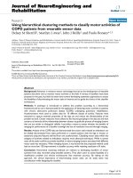
ceptable and applications remain able to perform their tasks.
An example of the application and FPGA utilization is show n
in Figure 5.
3.7. Conclusion
In this sec tion, we have described the components that are
required for the run-time loading and unloading of circuits
on an FPGA using an operating system. Checkpointing has
been used as a means to allow simulated partial dynamic re-
configuration in the absence of a practical partial dynamic
reconfiguration mechanism. The Minkowski sum algorithm
is used to identify locations of free resources for the execu-
tion of new circuits, which are then connected to external
memory by an on-chip network and memory arbiter. This
has been implemented and it has been shown capable of ex-
ecuting practical UAV applications.
4. SHARING FPGA COMPUTING AND POWER
RESOURCES ACROSS A SWARM OF UAVs
Sharing a single FPGA among many embedded tasks, allow-
ing them to be loaded at any time, is a necessary first step
to making these tasks mobile across a swarm of UAVs each
of which is fitted with an FPGA. In this sec tion, we explain
how the operating system is extended to support this mobil-
ity. In the next section, the autonomous agent-based design
of the distributed operating system and the fuzzy rule base
that controls task migration are described. An agent-based
environment has been chosen for the swarm because it al-
lows members of the swarm to be considerd as disposable in
a way that does not place the whole swarm in jeopardy. The
behavior of each agent in an autonomous agent-based envi-
ronments is usually governed by rules which are specific to
each agent. We descr ibe how we have adopted a fuzzy rule
base for our agents.
4.1. Using agents for resource sharing
In this section, the justification for using agents is presented
and the consequences for this choice on the swarm are ex-
plained. A swarm of UAVs is a collection of many different
types of resources ranging from platforms, to sensors and ef-
fectors, to processing units. To best make use of these, they
must be interconnected in such a way as to enable them to
not only share the resource, but manage it responsibily. This
requires coordination in resource allocation which involves
balancing the needs of applications with other resources such
as power and bandwidth. Although there are many ways in
which this can be implemented, the nature of a swarm makes
any form of centralized control undesirable as it introduces a
single point of failure in a system prone to unreliability.
Computing agents are a distributed computing paradigm
that suits such environments. Agents are a subclass of com-
puter programs that exhibit the properties of autonomy, so-
cial ability, reactivity, and proactiveness. The agents can be
further categorized as mobile or static agents. A static agent
mayrepresentaresourcesuchasacamerawhichisfixedto
a platform whereas mobile agents represent applications that
may move their execution between platforms. Unlike many
other distributed computing par adigms, mobile agents allow
the transfer of state, not just execution, between nodes. This
is done under the agents own control, which allows appli-
cations to customize migration rules which can further en-
hance the advantages of the distributed system by taking ad-
vantage of application specific knowledge. The behavior of
an agent is specified as a set of basic rules that govern its be-
havior. A static sensor, for example, might have rules which
specify under what conditions it should share data with an
application. The agent may rank connected applications in
order of mission priority and throttle the bandwidth of triv-
ial applications in favor of mission critical tasks.
When developing resources or applications as agents in
our network, the implementation is connected to the net-
work by an agent interface. A skeleton agent interface pro-
vides basic communication functionality allowing the re-
source to be visible and accessible by other networked agents.
Agents are defined on the network by their location and abil-
ities. These are used at the time of creation to create a unique
tuple which identifies that agent on the node. The tuple is
defined as sequence number
, home node, class, current node,
ability list, where “sequence number” is a unique identifica-
tion number with respect to the “home node,” which is the
node that the agent was created on. “class” is the type of
agent, “current node” is the node that the agent currently ex-
ecutes on, and finally the “ability list” describes the agent’s
abilities.
We have observed that the aggregation of agents will
produce emergent behaviors which c an be guided by rules
to achieve some overriding objective such as equalizing the
power available in the swarm.
4.2. The UAV swarm agent environment
In this section, the infrastructure that supports the agent en-
vironment is described.
In order for these agents to be useful they must exist in
a networked environment that supports their basic require-
ments, which are
(i) discovery of other agents,
(ii) communication with other agents,
(iii) providing information about other nodes,
(iv) migration between nodes.
Further requirements of the environment are
(i) transaction type migration—all or nothing,
(ii) message routing and forwarding.
10 EURASIP Journal on Embedded Systems
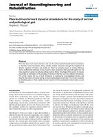
Figure 5: The simulation application showing the output of the tracking and Sobel algorithms is shown in (a) and FPGA utilization shown
in (b). The memory arbiter (top polygon), tracking (middle polygon), and Sobel (bottom polygon) can clearly be seen in the utilization
window.
If agents are to communicate and exchange information, they
must first be able to find the location of other agents of in-
terest. To facilitate this, each node maintains a list of agents
currently at its locale. Nodes periodically exchange or update
peers so that a global snapshot of agents is available at each
node. When an agent wishes to communicate with another,
the agent sends the message to the host on which it is execut-
ing along with the sequence number/home node key that iden-
tifies the host on the network. The senders host then trans-
mits the message to the recipient’s host where it is passed to
the receiving application. Should a node receive a message
for a recipient that no longer exists on the network it must
update its peers and handle the undelivered message? If the
recipient has simply ended its execution, the message can be
deleted and an update of the current agents exchanged. If the
recipient has migrated, the message must be forwarded to the
agent’s new location and the agent table updated.
Mobile agents require the most support for the migra-
tion process. Performing a migration is an expensive process
costing both power and throughput (due to downtime), and
because of this, agents need as much information as possi-
ble available to make the best decisions possible. Informa-
tion that a mobile agent may use include the CPU and mem-
ory usage on the target host platform, its physical location,
the availability of reconfigurable computing resources, power
usage, bandwidth to various other nodes, and the availabil-
ity of other local resources. All these information are made
available on request to mobile agents using messages passed
directly to the target node.
If a mobile agent wishes to migrate to another node, a
sequence of transac tions takes place between itself and the
target node to transfer its state and execution to the new loca-
tion. First, the agent framework requires developers to write
methods to extract agent state and allow itself to resume a
state. When an agent is to migrate, it sends a request to the
target host, which then invokes a new instance of that agent’s
class in a sleep state (so it is not performing any processing).
The new instance is given a temporary identifier which is
returned to the migrating node. When this is received, the
agent stops performing its task, captures its state, and sends
it to the sleeping node which restores itself to this state. At
this point, both nodes are notified and the original instance
of the mobile agent ends its execution. The new instance is
then free to resume its task in the new location. The thing to
note here is that the developer of the mobile agent has not
written code for migration, just recover and restore meth-
ods. The actual migration is performed upon a request to the
agent environment.
4.3. Migration rules
While an application is performing its processing, the agent
component is constantly examining the network for oppor-
tunities to increase its effectiveness through migration. The
search for migrations is implemented in a separate thread so
as not to directly affect the application. The objective for the
application developer is to define a set of conditions where
a migration is desir a ble. Fuzzy logic has been used thus far
as the basis of expressing the desired behavior, although the
framework al l ows the developer to use virtually means for
expressing these conditions as rules.
Although the costs of migration in terms of resources can
be modeled, the environment is dynamic and the advantage
of migrating an application from one platform to another
cannot be guaranteed. Fuzzy logic is used because it allows
us to easily model this uncertainty. Consider the case of ap-
plications searching for targets within a subregion of the op-
erating area of a swarm of UAVs. If there are many applica-
tions executing within this swarm, it may not b e possible to
control the flight of the UAV so the applications’ rules must
express its “desire” to migrate to planes that can focus sen-
sors into this region. A high-level description of a rule that
will exhibit the behavior is
“If (the visibility of sensor s on this
platform is LOW) AND (the visibility
on another platform is HIGH) then
(desire to migrate is HIGH)”
This rule may be combined with others that compare the
power and bandwidth availability, the types of sensors and
D. Kearney and M. Jasiunas 11
utilization, as well as the cost of migrations and produce the
desired behavior.
5. CONCLUSION
Swarms of small UAVs can benefit from the use of embedded
reconfigurable computers. By extending an operating system
for reconfigurable computing, we have constructed a dis-
tributed operating system that allows mobile agent enabled
applications to migrate their execution between networked
platforms based on fuzzy logic rules. This allows applica-
tions to not only migrate to increase performance or move
closer to sources of data, but also allows power to be managed
across a swarm to increase its overall mission time. The sim-
ulation of real applications shows that applications are still
able to perform with a cceptable performance when forced to
share memory.
ACKNOWLEDGMENT
The authors would like to acknowledge the support of the Sir
Ross and Sir Keith Smith Fund.
REFERENCES
[1] M. Dorigo, V. Maniezzo, and A. Colorni, “Ant system: opti-
mization by a colony of cooperating agents,” IEEE Transactions
on Systems, Man and Cybernetics—Part B,vol.26,no.1,pp.
29–41, 1996.
[2] SpaceDaily, “Both Civil and Military Needs Driving Euro-
pean UAV Market,” 2004, />uav-04a.html.
[3] S. Herwitz, L. Johnson, J. Arvesen, R. Higgins, J. Leung, and
S. Dunagan, “Precision Agriculture as a commercial applica-
tion for solar-powered unmanned aerial vehicles,” in Proceed-
ings of AIAA’s 1st Technical Conference and Workshop on Un-
manned Aerospace Vehicles, Systems, Technologies, and Opera-
tions, Portsmouth, Va, USA, May 2002.
[4] UAV World, “US Homeland Security ponders prospective
UAV test centre,” 2003, />disc1/
000000e9.htm.
[5] V. G. Ambrosia, S. S. Wegener, D. V. Sullivan, et al., “Demon-
strating UAV-acquired real-time thermal data over fires,” Pho-
togrammetric Engineering and Remote Sensing, vol. 69, no. 4,
pp. 391–402, 2003.
[6] S. C. Wong, M. Jasiunas, and D. Kearney, “Towards a recon-
figurable tracking system,” in Proceedings of the 15th Interna-
tional Conference on Field Programmable Logic and Applica-
tions (FPL ’05), pp. 456–462, Tampere, Finland, August 2005.
[7] L. Johnson, S. Herwitz, S. Dunagan, B. Lobitz, D. Sullivan, and
R. Slye, “Collection of ultra high spatial and spect ral resolu-
tion image data over California vineyards with a small UAV,”
in Proceedings of the International Symposium on Remote Sens-
ing of Environment, Honolulu, Hawaii, USA, November 2003.
[8] K. Compton and S. Hauck, “Reconfigurable computing: a sur-
vey of systems and software,” ACM Computing Surveys, vol. 34,
no. 2, pp. 171–210, 2002.
[9]S.D.Brown,R.Francis,Z.Vranesic,andJ.Rose,Field-
ProgrammableGateArrays, Kluwer Academic, Dordrecht, The
Netherlands, 1992.
[10] C. Sanderson, “FPGA computing provides superior perfor-
mance density for UAV applications,” COTS Journal, pp. 82–
85, 2003.
[11] L. Nork and J. Robinson, “UAV multi-mission payloads de-
mand a flexible common processor,” COTS Journal, pp. 78–81,
2003.
[12] H. Yamada, T. Tominaga, and M. Ichikawa, “An autonomous
flying object navigated by real-time optical flow and visual
target detection,” in Proceedings of IEEE International Confer-
ence on Field-Programmable Technology (FPT ’03), pp. 222–
227, Tokyo, Japan, December 2003.
[13] J. E. Scalera, C. F. Jones III, M. Soni, et al., “Reconfigurable ob-
ject detection in FLIR image sequences,” in Proceedings of the
10th Annual IEEE Symposium on Field-Programmable Custom
Computing Machines (FCCM ’02), pp. 284–285, Napa, Calif,
USA, April 2002.
[14] M. Petronino, R. Bambha, J. Carswell, and W. Burleson, “An
FPGA-based data acquisition system for a 95 GHz W-band
radar,” in Proceedings of IEEE International Conference on
Acoustics, Speech, and Signal Processing (ICASSP ’97), vol. 5,
pp. 4105–4108, Munich, Germany, April 1997.
[15] G. Wigley and D. Kearney, “The development of an operat-
ing system for reconfigurable computing,” in Proceedings of the
9th Annual IEEE Symposium on Field-Programmable Custom
Computing Machines (FCCM ’01), pp. 249–250, Rohnert Park,
Calif, USA, April-May 2001.
[16] M. Jasiunas, “Combined run-time area allocation and long
line re-routing for reconfigurable computing,” in Proceedings
of IEEE International Conference on Field-Programmable Tech-
nology (FPT ’03), pp. 407–410, Tokyo, Japan, December 2003.
[17] M. A. George, M. Pink, D. Kearney, and G. B. Wigley, “Effi-
cient allocation of FPGA area to multiple users in an operat-
ing system for reconfigurable computing,” in Proceedings of the
International Conference on Engineering of Reconfigurable Sys-
tems and Algorithms (ERSA ’02), Las Vegas, Nev, USA, June
2002.
[18] A. Sharma, M. A. George, and D. Kearney, “Packing with
boundar y constraints for a reconfigurable operating system,”
in Proceedings of 8th Asia-Pacific Conference on Advances in
Computer Systems Architecture (ACSA C ’03), pp. 236–245,
Aizu-Wakamatsu, Japan, September 2003.
[19] D. Kearney and G. Veldman, “A concurrent multi-bank mem-
or y arbiter for dynamic IP cores using idle skip round robin,”
in Proceedings of IEEE International Conference on Field-
Programmable Technology (FPT ’03), pp. 411–414, Tokyo,
Japan, December 2003.
[20] D. Kearney and G. Veldman, “Evaluation of network topolo-
gies for a run-time re-routable network on a programmable
chip,” in
Proceedings of IEEE International Conference on Field-
Programmable Technology (FPT ’03), pp. 178–185, Tokyo,
Japan, December 2003.
[21] A. Finn, K. Brown, and T. Lindsay, “Miniature UAV’s & fu-
ture electronic warfare,” Electronic warfare and radar division
DSTO.
[22] D. Ledger, “Electronic warfare capabilities of mini UAVs,”
/>[23] H. Donnelly, “Swarming UAVs,” itary-aero-
space-technology.com/article.cfm?DocID
=686.
[24] M. Wooldridge and N. Jennings, “Intelligent agents: theory
and practice,” Knowledge Engineering Review,vol.10,no.2,pp.
115–152, 1995.
12 EURASIP Journal on Embedded Systems
[25] D. Kotz and R. S. Gray, “Mobile agents and the future of the in-
ternet,” ACM SIGOPS Operating Syste ms Rev iew, vol. 33, no. 3,
pp. 7–13, 1999.
[26] G. Weiß, M. Rovatsos, and M. Nickles, “Capturing agent au-
tonomy in roles and XML,” in Proceedings of the 2nd Interan-
tional Joint Conference on Autonomous Agents and Multiagent
Systems (AAMAS ’03), pp. 105–112, Melbourne, Australia, July
2003.
[27] D. S. Milojicic, F. Douglis, Y. Paindaveine, R. Wheeler, and S.
Zhou, “Process migration,” ACM Computing Surveys, vol. 32,
no. 3, pp. 241–299, 2000.
[28] M. R. Genesereth and S. P. Ketchpel, “Software agents,” Com-
munications of the ACM, vol. 37, no. 7, pp. 48–53, 1994.
[29] M. Tambe, “Implementing agent teams in dynamic multiagent
environments,” Applied Artificial Intelligence, vol. 12, no. 2, pp.
189–210, 1998.
[30] D. Smith and D. Bhatia, “RACE: reconfigurable and adaptive
computing environment,” in Proceedings of the 6th Interna-
tional Workshop on Field-Programmable Logic and Applications
(FPL ’96), pp. 87–95, Darmstadt, Germany, September 1996.
[31] J. S. N. Jean, K. Tomko, V. Yavagal, J. Shah, and R. Cook, “Dy-
namic reconfiguration to support concurrent applications,”
IEEE Transactions on Computers, vol. 48, no. 6, pp. 591–602,
1999.
[32] D.Davis,M.Barr,T.Bennett,etal.,“AJavadevelopmentand
run-time environment for reconfigurable computing,” in Pro-
ceedings of the 12th International Parallel Processing Sympo-
sium and 9th Symposium on Parallel and Distributed Processing
(IPPS/SPDP ’98), pp. 43–48, Orlando, Fla, USA, March-April
1998.
[33] R. Moseley, “Reconnetics: a system for the dynamic imple-
mentation of mobile hardware processes in FPGAs,” in Pro-
ceedings of the 25th WoTUG Technical Meeting on Communi-
cating Process Architectures, pp. 167–180, Reading, Mass, USA,
September 2002.
[34] D. Rakhmatov, S. B. K. Vrudhula, T. J. Brown, and A. Nagaran-
dal, “Adaptive multiuser online reconfigurable engine,” IEEE
Design and Test of Computers, vol. 17, no. 1, pp. 53–67, 2000.
[35] D. Rakhmatov, “Dynamic scheduling in run-time reconfig-
urable systems,” M.S. thesis, University of Arizona, Tempe,
Ariz, USA, 1998.
[36] R. Kress, “A fast reconfigurable ALU for Xputers,” Ph. D. dis-
sertation, Kaiserslautern University, Kaiserslautern, Germany,
1996.
[37] R. Kress, R. W. Hartenstein, and U. Nageldinger, “An operating
system for custom computing machines based on the Xputer
paradigm,” in Proceedings of the 7th Internat ional Workshop on
Field-Programmable Logic and Applications (FPL ’97), pp. 304–
313, London, UK, September 1997.
[38] A. Marquardt, V. Betz, and J. Rose, “Timing-driven place-
ment for FPGAs,” in Proceedings of the 8th ACM/SIGDA In-
ternational Symposium on Field Programmable Gate Arrays
(FPGA ’00), pp. 203–213, Monterey, Calif, USA, February
2000.
[39] B. Chazelle, “The bottom-left bin-packing heuristic: an effec-
tive implementation,” IEEE Transactions on Computers, vol. 32,
no. 8, pp. 697–707, 1983.
[40] K. Bazarg an, R. Kastner, and M. Sarrafzadeh, “Fast template
placement for reconfigurable computing systems,” IEEE De-
sign and Test of Computers, vol. 17, no. 1, pp. 68–83, 2000.
[41] M. L. Silva and J. C. Ferreira, “Support for partial run-time
reconfiguration of platform FPGAs,” Journal of Systems Archi-
tecture, vol. 52, no. 12, pp. 709–726, 2006.
[42] M. Huebner, T. Becker, and J. Becker, “Real-time LUT-
based network topologies for dynamic and partial FPGA self-
reconfiguration,” in Proceedings of the 17th Symposium on In-
tegrated Circuits and Systems Design (SBCCI ’04), pp. 28–32,
Pernambuco, Brazil, September 2004.
David Kearney is the leader of the recon-
figurable computing laboratory at the Uni-
versity of S outh Australia. This laboratory
is home to the largest reconfigurable com-
puter cluster in Australia. Kearney has more
than ten years experience in research in elec-
trical engineering and computer science.
His research interests include the hardware
Join Java compiler, operating systems for
FPGAs and applications of reconfigurable
computing to image processing for unpiloted airborne vehicles and
bioinformatics. He has published more than 50 papers in interna-
tional conferences and journals.
Mark Jasiunas completed his Bachelor of
Computer Science (software engineering)
and Honours at the University of South
Australia before moving on to his current
position as a Research Programmer and
Ph.D. student in the reconfigurable com-
puting laboratory. His current research in-
terests include UAV autonomy, operating
systems for FPGAs, and HW/SW mobile
agents.