Báo cáo hóa học: " Research Article Automatic Generation of Spatial and Temporal Memory Architectures for Embedded Video Processing Systems" docx
Bạn đang xem bản rút gọn của tài liệu. Xem và tải ngay bản đầy đủ của tài liệu tại đây (1.1 MB, 10 trang )
Hindawi Publishing Corporation
EURASIP Journal on Embedded Systems
Volume 2007, Article ID 75368, 10 pages
doi:10.1155/2007/75368
Research Article
Automatic Generation of Spatial and Temporal Memory
Architectures for Embedded Video Processing Systems
H
˚
akan Norell, Najeem Lawal, and Mattias O’Nils
Electronics Design Div ision, Department of Information Technology and Media, Mid Sweden University, 851 70 Sundsvall, Sweden
Received 1 May 2006; Revised 11 October 2006; Accepted 15 October 2006
Recommended by Heinrich Garn
This paper presents a tool for automatic generation of the memory management implementation for spatial and temporal real-
time video processing systems targeting field programmable gate arrays (FPGAs). The generator creates all the necessary memory
and control functionalit y for a functional spatio-temporal video processing system. The required memory architecture is auto-
matically optimized and mapped to the FPGAs’ memory resources thus producing an efficient implementation in terms of used
internal resources. The results in this paper show that the tool is able to efficiently and automatically generate all required memory
management modules for both spatial and temporal real-time video processing systems.
Copyright © 2007 H
˚
akan Norell et al. This is an open access article distributed under the Creative Commons Attribution License,
which permits unrestricted use, distribution, and reproduction in any medium, provided the original work is properly cited.
1. INTRODUCTION
In today’s society it is apparent that video systems are gener-
ally becoming standard applications. These systems are play-
ing a central role in the daily life of the majority of homes.
Embedded video applications contained in home entertain-
ment systems are becoming more and more complex as is the
processing required. Real-time streamed video is common
and this places significant constraints on the processing ap-
plications as the data rates increase towards high-definition
television (HDTV). Surveillance application is one of the
most rapidly developing areas. Video m onitoring is now
present in almost every store or public place. The amount
of video data produced by these systems requires them to be
able to efficiently der ive features or events that are present in
the scene. This, in turn, has led to an increased requirement
to enable more complex operations such as prefiltering, ob-
ject recognition, or compression to be performed as close as
possible to the video source. This advance has led to the rapid
development of smart cameras which have the ability to ful-
fill these requirements. Complex reconfigurable embedded
systems with advanced image processing functions must be
rapidly developed which are also available at a low cost [1].
Video processing systems required in the broadcast and
postprocessing market are typically in the low-volume and
high-cost segment. These are systems performing real-time
high-resolution (2048
2048@24 fps) high-performance
computation with complex motion compensating spatio-
temporal filters [2]. The trend is for the algorithm complex-
ity to increase over t ime. This increased complexity is often
reflected in the memory usage. One example involves the
memory usage required by algorithms with temporal data
dependencies. In order to manage the increased complexity
and the requirement for a shorter period of time-to-market,
efficient toolsets are required. Effective development t ools
can abstract the hardware layer and ease the development
by enabling the systems designer to perform actual hardware
implementation without extensive hardware knowledge.
Attempts at reducing the time-to-market of modern elec-
tronic systems have, in general, increased the motivation to
develop automation tools for system modeling [3–8], opti-
mization [9], simulations [3, 10, 11], and synthesis [9, 12–
17]. The main objective of these automation tools is to em-
power the designer not to only have the ability to cope with
increasing design complexity but also to generate efficient de-
signs as quickly as possible. In this paper, we present a design
suite for generating the architecture for real-time spatial and
temporal image/video filters targeting field programmable
gate arrays (FPGAs) thus enabling designers to cope with de-
sign complexities and time-to-market constraints.
The outline of this paper is as fol l ows. Firstly, related
work is presented and then the background and the scope
of this paper are stated. We then present the real-time video
processing system (RTVPS) synthesis and limitations in
2 EURASIP Journal on Embedded Systems
Section 4. The results are presented in Section 5 followed by
the discussions and conclusions in Section 6 and Section 7,
respectively.
2. RELATED WORK
This work is built on the success of many previous works
in the area of memory estimation, optimization, mapping,
memory accessing, and interfacing for both on- and off-chip
memory allocations. However, there is a rather limited selec-
tion in the literature of work relating to homogenous tools
which unify the management of on- and off-chip memories
in a seamless manner and, additionally, of tools able to han-
dle boundary conditions for real-time video processing sys-
tems.
Reference [18] presents the design and implementation
of a high-level core generator for 2D convolution operations,
which contains the parameters and ability to scale in terms of
the convolution window size and coefficients, the input pixel
word length, and the image size. The work has been extended
to be generic and automatically implemented. The allocation
of line buffers required by the convolution cores has also been
investigated. The work by Schmit and Thomas [19]performs
array grouping (vertically and horizontally) and dimensional
transformation (array widening and array narrowing). Array
widening is useful for read-only arrays and those accessed in
loops with an unrolled number of iterations. Jha and Dutt
[20] presented two algorithms for memory mapping. The
first, linear memory mapping, approximates target memory
word-count to the largest power-of-two that is less than or
equal to the source memory word-count. The second, ex-
haustive memory mapping, assumes that the target memory
module may have a larger bit-width and word count. Lawal
et al. [21] presented a heuristics-based algorithm for allocat-
ing FPGA block RAMs for the implementation of RTVPS. To
achieve optimal results, dual port capabilities of block RAMs
were exploited and vertical grouping of the line buffers as
well as dynamic allocation of memory objects to multiple
block RAMs were utilised. The effectiveness of the algorithm
was shown through the implementation of realistic image
processing systems.
With reference to background memory management,
Th
¨
ornberg et al. [22] proposed a methodology for back-
ground memory estimation and optimization. A tool imple-
menting the methodology to generate optimized estimates
of the memory requirements of an RTVPS was also pre-
sented. Weinhardt and Luk [23] present a technique that
optimally al locates memory objects to a set of background
memory banks using integer linear programming (ILP). The
technique achieved optimisation by parallelisation of data
accesses through pipelining. Diniz and Park [24] addressed
the problems associated with external memory interfacing
by exploiting target memory architecture and the application
memory access pattern.
We have taken advantage of these, and other notable
works, in developing the work presented in this paper. To
use the architecture generator presented in this paper, the
designer is only required to specify the memory requirements
of a neighbourhood oriented RTVPS and continue with the
development of the core RTVPS. This work will implement
data storage to both on- and off-chip memories and provide
interface for the pixel data required by the filter. FlexFilm
[2] and Imagine [25] are the closest related research works
at the present time. FlexFilm is a top-end multi-FPGA hard-
ware/software architecture, for computation intensive, high-
resolution real-time digital film processing. The architecture
implements the external memories and achieved record per-
formance. However, very little was reported concerning the
allocation to on-chip memory. Our work differs from the
Imagine Stream Architecture since our core processing tech-
nology is FPGA.
3. BACKGROUND
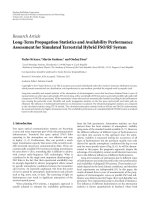
This work was de veloped as part of the IMEM-IMapper de-
sign tool [8, 10]. The primary objective is to assist designers
in a seamless implementation of neighbourhood-oriented
RTVPS filters by handling the memory requirements and
boundary conditions of a filter. IMEM is a system description
dataflow gr a ph that generates a fully synthesisable real-time
register-transfer level (RTL) model of a RTVPS. Its basis lies
in the knowledge that the filter kernel and the interface and
memory model of a real-time video processing system can be
described separately [10]. Parameters extracted from IMEM
include image size, kernel size, colour-model, and data de-
pendencies. Naturally, an RTVPS will consist of several such
filters, which may possibly contain varying values.
Each set of parameters is the interface and memory
model generated for each of the filters in RTVPS. The full
model also includes interfaces and operators relative to each
other. The IMEM model can be imported into our automatic
synthesis tool IMapper which generates the target-specific
implementation of the interface and memory model. A man-
ually refined filter kernel is then merged with the automat-
ically generated interface and memory model into target-
specific RTL-code. This video system implementation can
be further transformed into gate-level code using a target-
specific synthesis tool. Figure 1 shows the relationship be-
tween IMEM and IMapper.
This work implements the interface and memory model
and the filter boundary conditions thus freeing up the de-
signer to implement the filter. The presented tool includes
the following work.
(i) Automatic allocation of line buffers and frame buffers
for embedded block RAMs and external RAMs, re-
spectively.
(ii) Automatic address generation and interfaces for the
two memory hierarchies (off and on-chip memory).
(iii) Automatic implementation of boundary conditions.
(iv) Implementation of parallel access to all pixel data re-
quired in a neighbourhood (spatial or temporal).
(v) Provision of a test-bench with valid image streaming
and image captur ing for efficient simulation and veri-
fication of a customized video processing algorithm.
H
˚
akan Norell et al. 3
Simulation
input stimuli
IMEM
conceptual modelling
Functional
simulation data
Interface and
memory model
Filter kernel
RTL-code generation in
IMapper
Filter kernel,
refined into RTL-
code
Target-specific
RTL-code
RTL to gate level synthesis
Target
architecture
Figure 1: The IMEM workflow.
Linebuffers
SLWC
Pixel
switch
Window
ctrl.
.
.
.
VDMC
External SS/SDRAM
VIP algorithm
Sync.
Figure 2: Architectural overview.
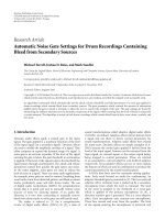
4. RVTPS SYNTHESIS
As described in the previous section, the designer speci-
fies the required system parameters derived from either the
IMEM environments or with parameters derived from an-
other source. From these parameters, the IMapper creates
the required hardware structure as depicted in Figure 2.The
architecture is derived from three major parts, the sliding
window controller (SLWC), video data memory controller
(VDMC), and the synchronisation block. To ease the imple-
mentation of a custom filter function, an HDL template pro-
viding the necessary interface for seamless integration in the
design flow is generated. To illustrate the architecture in de-
tail, each of the subparts is presented in the following sec-
tions.
4.1. Memory allocation
Almost all image neighbourhood operations using either a
continuous or block wise pixel flow are processed by using a
sliding window. Line buffers a re required to store the neces-
sary data in the spatial neighbourhood.
They are implemented using global memory object
(GMO) architecture [26]. For each operator in the neigh-
bourhood-oriented RTVPS, GMO can b e achieved through
W
Ri
= n
lines
w
p
,(1)
where W
Ri
is the w idth of the GMO, n
lines
is the number of
required memory objects for an operator, and w
p
is the bit
width representing a pixel.
The length of the GMO is equal to that of the memory
objects forming it [26]. GMOs require a minimal number of
memory entities in comparison to the direct mapping archi-
tecture. Consequently, the number of memory accesses for
an RTVPS operation is minimal for a GMO.
Implementing GMOs and their allocation to block RAMs
requires an efficient algorithm so that accessing the allocated
data and reconstructing the line buffers occurs in a seam-
less manner with minimal overhead resource and low latency.
Two al location algorithms (one optimized for heuristics [21]
and the other for ILP [22]) have been developed and im-
plemented for this purpose. The algorithm in [ 21]creates
the GMOs based on (1). It partitions the GMOs to ensure
that their widths conform to those specified by the FPGA
thus ensuring optimal usage of the block RAMs. The algo-
rithm takes advantage of the dual port capabilities of the
block RAMs to achieve optimal allocations and the possibil-
ity of allocating a GMO to as many block RAMs as required.
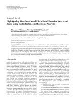
Figure 3 depicts the method used by the algorithm to allo-
cate four memory objects according to the GMO architec-
ture. In Figure 3(a), the four line buffers were grouped to-
gether to form one GMO. Assuming the GMO is 640-pixel
wide, then if it were to be a llocated on a Xilinx Spartan 3
FPGA, it would require partitioning into two segments, of
widths 32 and 16, as it is not possible to have a data path
width of 48 on a Xilinx Spartan 3 FPGA. In addition, since
each block RAM is 16 Kibit (excluding parity feature), the
first segment, of width 32, would require 2 block RAMs, thus
creating two partitions. The second segment would require
a single partition on a block RAM. Figure 3(b) illustrates the
partitioning of the GMO while Figure 3(c) shows how the
GMO is allocated to two block RAMs using a data path of
32 bits and 16 bits. The main objective of the allocation algo-
rithm is to minimise block RAM usage. This is achieved in
Figure 3 since two block RAMs were used as opposed to the
four block RAMs required for the direct mapping of the four
line buffers. With direct mapping, we refer to memory map-
ping in which each line buffer is allocated to one block RAM,
without resource sharing. In the figure op, seg, par, and BR
represent the operator, segment, partition, and block RAM
numbers, respectively, and w here Ports A and B are the two
io-ports available on a block RAM configured as a dual port
(BR2). In this case only Port A is used on a block RAM con-
figured as single port (BR1). In [27], two possible approaches
for accessing and reconstructing the allocated memory ob-
jects were presented and compared.
The implemented GMO takes the form of a circular
buffer allocated to a set of memory locations. The example
4 EURASIP Journal on Embedded Systems
L 12
L
12
L
12
L
12
L
48
R
i
op id = 1
(a)
op = 1 seg = 2 par = 1
640
16
512
32
op
= 1 seg = 1
par
= 1
Allocation
128
32
op
= 1
seg
= 1
par
= 2
640
48
op
= 1
(b)
512 32
op
= 1 seg = 1
par
= 1
Port A BR1
Unused memory 2 kBit
op
= 1 seg = 2 par = 1
640
16
Port A
BR2PortB
128
32
op
= 1
seg
= 1
par
= 2
(c)
Figure 3: Implementation of memory architecture.
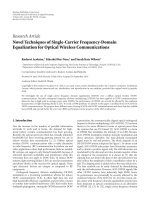
in Figure 4 depic ts a set of eight m emory locations, n 8to
n
1, which are indexed by a pointer in a modulus-8 or-
der. For every pointer position, pixel data P
n 8
is firstly read
and then pixel data P
n
is written. The benefit of the Xilinx
block RAM is that it allows first-read-then-write operation
to be executed in one single clock cycle. In the continuous
case of a sliding window the mask window will overlap the
image under processing when the border is reached, creating
a boundary condition, as shown in Figure 5.
For each mask window, b possible numbers of bound-
ary sets are required to be handled, depending on how many
mask positions fall outside the image perimeter. An exam-
ple of a boundary set is shown as a dar k grey shaded area in
Figure 5:
b
= 4
(ω 1)
2
2
ω 1
2
. (2)
Equation (2) holds true, provided that ω
width(I)andω
is an odd number, where ω is the window width and I the
image under processing, according to Figure 5.
For each separate boundary, care has to be taken in order
to prevent the introduction of nonvalid data. With nonvalid
data, we refer to undefined or extreme values that would cor-
rupt or bias the following processing functions. Positions in
the window not filled by correct data can be expressed as a
set, B
W I
C
,whereW is the desired processing window
and I the image under processing, according to Figure 5.
For each boundary, the set B is filled with pixels according
to B
w
c
,wherew
c
can be configured to originate from the
valid central spatial pixel, inside the image, of the window W,
defined in (3), or for the processing function suitable value:
w
c
= W
ω +1
2
,
ω +1
2
. (3)
From these boundary conditions, a boundary state controller
(BSC) is generated, which provides the necessary control sig-
P
n 8
P
n 7
P
n 6
P
n 5
P
n 4
P
n 3
P
n 2
P
n 1
Current pointer
position
incremented at
every clock cycle
After read,
write pixel P
n
Firstly,
read pixel P
n 8
Figure 4: Read-write cycle.
nals for the spatial or temporal window buffers. The con-
troller monitors the inputted vertical and horizontal syn-
chronisation signals and keeps track of the window position
relative to the image boundary. If a boundary is within the
window, each pixel, falling outside the image, is replaced. The
controller and the required line buffers form the temporal
architecture. An example of an architecture which has a tem-
poral depth of n frames is depicted in Figure 6.
The structure of the line buffers that provide the sliding
window is created by block RAMs, allocated according to the
method previously described. Line buffers are instantiated
according to the requirement in the specification and form
the spatial pixel buffer which has two lines in the example
depicted in Figure 7.
The BSC is generated from generic expressions which
contain the rules for the operations requiring to be per-
formed when an image boundary is reached. At this point,
the controller determines which positions in the filter mask
must be replaced.
H
˚
akan Norell et al. 5
W
ω
I
Width
Height
.
.
.
.
.
.
Figure 5: Illustration of boundary condition.
1
2
3
Boundary
state
control
.
.
.
S
t=2n+1
S
t=1
S
t=0
.
.
.
.
.
.
1. Synchronization and control
2. Temporal pixel data
3. Temporal windows
Figure 6: Temporal buffer architecture for n frames.
The control signals generated in the BSC are fed into the
line buffer and are utilized by a pixel switch. The replacement
is performed in the boundary pixel switch, at which the de-
fault boundary values can be chosen to originate from either
an external constant or an existing mask position as depicted
in Figure 7.
4.2. Temporal memory controller architecture
The architecture generator supports static random access
memories (SRAMs) in addition to synchronous dynamic
random access memories (SDRAMs). The choice of mem-
ory technology is mainly dependent on the type of system
to be implemented. SRAMs are suitable for video process-
ing systems with a nonpredictable read-write access pattern,
for example, block search, due to the internal design that
eliminates latency between read and write cycles. For stream-
oriented applications, such as filter applications with regular
read and write patterns, SDRAMs are suitable.
Read and write accesses can be performed in burst mode
and scheduled to optimize the related penalties. Limita-
tions associated with the two memory types are presented in
Section 4.3. The physical memory controller is interchange-
able with the memory controller generated by the memory
interface generator MIG from Xilinx [12]. This enables sim-
1
2
3
.
.
.
4
Line 1
Line 2
Boundary pixel sw.
Default bundary values
P9
P6
P3
P8
P5
P2
P7
P4
P1
1. Mask and line control
2. Serial pixel data
3. Window mask
4. Default boundary input
Figure 7: Line buffer architecture.
FrmCnt
RW
addr
PAT
+
Glue logic
PhyMemCtrl
4
1:N
Fifo
0
Fifo
1
.
.
.
Fifo
n 1
Fifo
n
Fifo
W
MemSyncCtrl
1
2
3
1. Temporal pixel data
2. Processed data
3. Syncronization
4. Physical memory interface
Figure 8: Video data memory controller (VDMC).
ple and seamless migration to other memory types if re-
quired. The read and write patterns stored in the physical ad-
dress table (PAT) can be configured during compile time. Ad-
dress generation is managed by configurable counters. The
address space is derived from the input video stream char-
acteristics, image width and height. In order to synchronise
data, a FIFO buffer is implemented for each required tempo-
ral level. The size of each buffer depends on the read-write
pattern and the number of temporal levels used. The de-
scribed architecture is depicted in Figure 8.
The total amount of block RAM available is 432 Kibit dis-
tributed on 24 18 Kibit blocks for a Spartan 3 1000. Using
6 EURASIP Journal on Embedded Systems
10
3
10
9
8
7
6
5
4
3
2
1
0
Maximum image width (pixels)
13579
Frame depth
3
3
5
5
7
7
9
9
Figure 9: Maximum buffer length.
(6) and the presented amount of block RAM yields a design
space ranging from 3
3 spatial neighbourhoods with an
image width exceeding 9 k pixels to a 9
99framespatio-
temporal neighbourhood 256-pixel width. The design set is
depicted in Figure 9. It should be noted that the architecture
generator is only limited by the available resources present in
the FPGA [26, 28]:
f
s
= F
r
I
width
I
height
,(4)
I
width max
=
BRAM
size
n (ω 1) bitwidth
. (5)
4.3. Memory I/O performance limitations
Video processing in general has reasonably high require-
ments in relation to the bandwidth. A system utilizing one
frame for processing, in general, does not require any exter-
nal buffering and can be implemented using only line buffers
placed on-chip. For spatio-temporal systems, several fr a mes
may require storage off-chip with on-chip line buffers. This
requires an efficient memory usage in order to handle the
amount of data requiring to be t ransferred.
Figure 10 illustrates the bandwidth requirements for dif-
ferent temporal depths and bit widths as well as memory in-
terface limits for a 153 MHz ZBT RAM memory. The graph
illustrates the filter bandwidth requirement for a specified
number of read/write (R/W) operations performed for each
input data. Two memory bandwidth limits are provided, 36-
and 72-bit access, to illustrate the maximum interface per-
formance.
Given the specified pixel rate f
s
, the minimum speed re-
quired for SDRAM and SRAM memory, f
Mem
SD
and f
Mem
zbt
,
can be derived from (6)and(7), respectively. In this case, Bl
is the burst length, w
op
and r
op
are the read and write oper-
ation, n is the number of the temporal frame depth, CAS is
Filter memory bandwidth requirement
versus frame depth @ 1367 p
768
10
2
150
100
50
0
Bandwidth requirement (Mibit/s)
8243236
Filter bitwidth (bits/pixel)
MemLim 36 bit
MemLim 72 bit
R/W
= 1/1
R/W
= 1/3
R/W
= 1/5
R/W
= 1/7
Figure 10: Bandwidth requirements.
thecolumnaddressstrobelatency,t
REF
is the time between
refresh, and w
op
and r
op
are binary operators representing a
read or write operation, respectively:
f
Mem
SD
= f
s
Bl (w
op
+ n r
op
)+CAS
Bl
+
1
t
REF
,(6)
f
Mem
zbt
= f
s
w
op
+ n r
op
. (7)
The system performance in terms of processed frames per
second is limited by the memory I/O performance due to the
large number of frames requiring to be transferred to-and-
from the FPGA. To provide the designer with a road-map for
the maximum image size, the system can perform up to a
given SRAM memory bandwidth, it is possible to use the ex-
pression in (8). It is derived by inserting (7) into (4)andmul-
tiplying by the bit width of the respective interface. A similar
operation is possible for SRAMs using (6).
An example is provided in Figure 11 depicting the image
height for temporal depths ranging from 1 to 9 frames using
a SRAM and SDRAM at 150 MHz speed. The figure also il-
lustrates the influence of the CAS latency on the performance
for SDRAMs using a burst length (Bl) of 8. This latency can
be thought of as the difference between each of the five line
pairs (the dashed line is the SRAM and the marked line is the
SDRAM). The graph shows that the performance exceeds the
HDTV performance 1367
768 progressive mode for a tem-
poral depth of 3 frames:
I
height max
=
f
Mem
bitwidth
Mem
I
width
F
r
(w
op
+ n r
op
) bitwidth
Pixel
.
(8)
In Figure 12 the solid line in each line pair describes the burst
length of 8 and the dot marked line is the burst length of one.
H
˚
akan Norell et al. 7
MaxheightforavailableBWversusframedepthh
10
2
20
18
16
14
12
10
8
6
4
2
0
Image height for SRAM (dashed) SDRAM
(solid marked) Bl
= 8 150 MHz @ 32 bit BW (pixels)
10 11 12 13 14 15 16 17 18 19 20
10
2
Image width (pixels)
Frames
= 1
Frames
= 3
Frames
= 5
Frames
= 7
Frames
= 9
CAS latency
Figure 11: Image height versus temporal depth.
This shows that a low-burst length severely degrades the per-
formance for low-frame depths. The selected type of memory
mainly depends on the application. Generally static memo-
ries have a low density compared to that of the corresponding
dynamic, which implies a high cost (area).
5. IMPLEMENTATION RESULTS
All parts of the architecture depicted in Figure 2 and Figures
13–15 have been implemented and the synthesis results us-
ing Xilinx integrated software environment (ISE) version 8.1i
targeting the Xilinx Spartan 3 1000 FPGA are shown. Sev-
eral results exceeded the resources available on one FPGA
chip and hence led to the use of multiple chips. T he figures
show the results for 3
3, 5 5, and 7 7 spatial neigh-
bourhoods implemented on 1-, 3-, 5-, 7-, and 9-frame tem-
poral neighbourhoods. Figure 13 shows the number of slices
and flip-flops. Figures 14 and 15 display the number of re-
quired block RAMs and maximum frequency, respectively.
The results were obtained for a resolution of 1367
768, with
24 bits per pixel. Table 1 shows the resources required by all
the components in Figure 2 apart from the filter core and the
external SDRAM used to support the implementation of a
filter with 3
3 spatial and a 7-frame temporal neighbour-
hood.
6. DISCUSSION
The results show that resources increase linearly with the di-
mensions of the spatial and temporal neighbourhoods and
that the maximum frequency decreases with the dimensions.
This architecture greatly reduces the designer’s development
time, increasing productivity and reducing time-to-market,
MaxheightforavailableBW(Bl = 1and8)
versus frame depth h
10
2
18
16
14
12
10
8
6
4
2
0
Image height for SDRAM Bl = 8and
Bl
= 1, 150 MHz @ 32 bit BW (pixels)
10 11 12 13 14 15 16 17 18 19 20
10
2
Image width (pixels)
Bl
= 8, frame depth (FD) 1, 3, 5,7, 9 relative bottom
Bl
= 1, frame depth (FD) 1, 3, 5,7, 9 relative bottom
FD
= 1
FD
= 3
FD
= 5
FD
= 9FD= 7
Figure 12: Burst length influence.
Synthesis results Spartran-3 1000
10
4
5
4.5
4
3.5
3
2.5
2
1.5
1
0.5
0
Resource usage
Slices
3
3
FF
3 3
Slices
5 5
FF
5 5
Slices
7 7
FF
7 7
Spatial neighbourhood
Frames
= 1
Frames
= 3
Frames
= 5
Frames
= 7
Frames
= 9
Figure 13: Synthesis results.
while, at the same time, providing efficient hardware mod-
ules. The generic nature of this architecture makes it subjec-
tive to the core filter algorithm rather than constraining it.
Hence it is only necessary for the designers to define the in-
terfaces required by the filter, implement the filter, and spec-
ify the required memory parameter. The architecture genera-
tor then generates the modules (as indicated in Figure 2)nec-
essary to manage the filter data requirements.
8 EURASIP Journal on Embedded Systems
Synthesis results Spartran-3 1000
120
100
80
60
40
20
0
Required number of block RAMs
3 35577
Spatial neighbourhood
Frames
= 1
Frames
= 3
Frames
= 5
Frames
= 7
Frames
= 9
Figure 14: Block RAM requirements.
Synthesis results Spartran-3 1000
140
120
100
80
60
40
20
0
Frequency (MHz)
3 35577
Spatial neighbourhood
Frames
= 1
Frames
= 3
Frames
= 5
Frames
= 7
Frames
= 9
Figure 15: Implementation frequency.
This significantly increases the possibility of rapid and
simple implementation of embedded video systems. The in-
cluded block RAM allocation and optimization method pro-
vide an automatic resource minimisation that would not
have been available to the designer without using this pre-
sented architecture generator.
The results in this paper show that the implementation
speed is close to the physical limitations of the block RAMs.
Thus, there are only limited possibilities for manual opti-
Table 1: Synthesis results for a spartan 3 1000.
3 3Output 7-frame
Tot al
SLWC sync. neighborhood
ADR ZBT
CTRL SRAM
CTRL
Number of slices 4262 41 98 74 4475
Number of slice
Flip-flops
7035 50 115 75 7275
Number of 4-input LUTs 392 65 132 37 626
Number of block RAMs 35 3 — — 38
misations. With regards to the cost aspects, the automatic
memory allocation, based on heuristics, produces a near op-
timal solution which is almost impossible to achieve manu-
ally. This implies that the tool is able, in fractions of a sec-
ond, to generate an implementation with comparable per-
formance and lower block RAM costs compared to a man-
ual implementation. When this is taken into consideration,
the proposed architecture generator efficiently generates ar-
chitectures for video systems utilizing sliding windows. For
example, the design time involved in implementing a sim-
ple 3
3 neighbourhood would require a significant bud-
get, but the complexities involved for a larger 9
9system
are too complex, for several designs, to be handled manu-
ally. The results also provide the designer with a road map
illustrating the limits involved for physical implementation.
Comparisons with previous works are discussed below.
With regards to boundary condition implementation
In [18], implementation of a pixel neighbourhood at the
boundaries was not considered. In this work, we have im-
plemented how it is possible to correct pixel data affected by
boundary conditions.
With regards to on-chip memory management
We have adopted the approach in [21]over[19]and[20]
since it exploits true dual port capabilities of block RAMs and
performs vertical grouping of line buffers and dynamic allo-
cation of memory objects to multiple block RAMs to achieve
optimal results.
With regards to background memory management
We used an IP core from Xilinx to allocate and retrieve video
frames from background memory. The core is very close to
[24] since a memory access pattern was exploited. Our work
can integrate with [22, 23]oranyotherbackgroundmemory
management tool available to the designer.
With regards to video processing platforms
The goal for our IMEM-IMAPPER software tool is to manage
(on- and off-chip) memory requirements and complexities
H
˚
akan Norell et al. 9
and provide interfaces for the required data thus enabling
designers to focus on core RTVPS algorithms. The synthe-
sizable VHDL code generated by our tool is capable of per-
formances in speed and video resolution comparable to Flex-
Film [2] and Imagine [25].
7. CONCLUSIONS
A fully automatic spatio-temporal video processing architec-
ture generator has been presented. It provides the designer
with a unique degree of flexibility in terms of both spatial and
temporal behaviour. Memory-optimized systems spanning
from a 3
3 spatial neighbourhood up to a 9 frame spatio-
temporal 7
7 pixel neighbourhood with off-chip memory
storage have been presented. However, it is easily possible to
generate larger designs if they are required. Usage of the pro-
posed architecture generator will greatly reduce the desig n
time and provide the designer with a powerful, efficient, and
fully automatic design tool suitable for embedded video pro-
cessing systems.
REFERENCES
[1] M. Bramberger, A. Doblander, A. Maier, B. Rinner, and
H. Schwabach, “Distributed embedded smart cameras for
surveillance applications,” Computer, vol. 39, no. 2, pp. 68–75,
2006.
[2] A. do Carmo Lucas, S. Heithecker, P. Ruffer, et al., “A recon-
figurable HW/SW platform for computation intensive high-
resolution real-time digital film applications,” in Proceedings
of Design, Automation and Test in Europe (DATE ’06), vol. 1,
pp. 1–6, Munich, Germany, March 2006.
[3] />[4] System-C Language Reference Manual, temc.
org.
[5] P.Green,M.Edwards,andS.Essa,“UMLforsystem-levelde-
sign: extending the object model for systems-on-chips,” in Sys-
temonChipDesignLanguages, A. Mignotte, E. Villar, and L.
Horobin, Eds., Kluwer Academic, Boston, Mass, USA, 2002.
[6]W.F.J.Verhaegh,P.E.R.Lippens,E.H.L.Aarts,J.H.M.
Korst, J. L. van Meerbergen, and A. van der Werf, “Modelling
periodicity by PHIDEO streams,” in Proceedings o f 6th Inter-
national Workshop on Hig h Level Synthesis, pp. 256–266, Dana
Point, Calif, USA, November 1992.
[7] D. D. Gajski, F. Vahid, S. Narayan, and J. Gong, Specification
and Design of Embedded Systems, Prentice-Hall, Englewood
Cliffs, NJ, USA, 1994.
[8] B. Th
¨
ornberg, H. Norell, and M. O’Nils, “Conceptual interface
and memory-modeling for real time image processing sys-
tems, IMEM, a tool for modeling, simulation, and design pa-
rameter extraction,” in Proceedings of IEEE Workshop on Mul-
timedia Signal Processing (MMSP ’02),St.Thomas,VirginIs-
lands, USA, December 2002.
[9]F.Catthoor,S.Wuytack,E.DeGreef,F.Balasa,L.Nachter-
gaele, and A. Vandecappelle, Custom Memory Management
Methodology, Kluwer Academic, Boston, Mass, USA, 1998.
[10] B. Th
¨
ornberg, H. Norell, and M. O’Nils, “IMEM: an object-
oriented memory- and interface modelling approach for real-
time video processing systems,” in Proceedings of the Forum on
Specification and Design Languages, Marseille, France, Septem-
ber 2002.
[11] P. R. Panda, “SystemC - a modeling platform supporting mul-
tiple design abstractions,” in Proceedings of the 14th Interna-
tional Symposium on System Synthesis (ISSS ’01), pp. 75–80,
Montreal, Quebec, Canada, September-October 2001.
[12] .
[13] .
[14] M. Edwards and B. Fozard, “Rapid prototyping of mixed hard-
ware and software systems,” in Proceedings of Euromicro Sym-
posium on Digital System Design , pp. 118–125, Dortmund,
Germany, September 2002.
[15] P. Mc Curry, F. Morgan, and L. Kilmartin, “Xilinx FPGA im-
plementation of an image classifier for object detection ap-
plications,” in Proceedings of IEEE International Conference on
Image Processing (ICIP ’01), vol. 3, pp. 346–349, Thessaloniki,
Greece, October 2001.
[16] R. Lauwereins, M. Engels, M. Ade, and J. A. Peperstraete,
“Grape-II: a system-level prototyping environment for DSP
applications,” Computer, vol. 28, no. 2, pp. 35–43, 1995.
[17] D. D. Gajski and L. Ramachandran, “Introduction to high-
level synthesis,” IEEE Design and Test of Computers, vol. 11,
no. 4, pp. 44–54, 1994.
[18] K. Benkrid and S. Belkacemi, “Design and implementation of
a 2D convolution core for video applications on FPGAs,” in
Proceedings of the 3rd International Workshop on Digital and
Computational Video (DCV ’02), pp. 85–92, Clearwater Beach,
Fla, USA, November 2002.
[19] H. Schmit and D. E. Thomas, “Synthesis of application-
specific memory designs,” IEEE Transactions on Very Large
Scale Integration (VLSI) Systems, vol. 5, no. 1, pp. 101–111,
1997.
[20] P. K. Jha and N. D. Dutt, “High-level library mapping for
memories,” ACM Transactions on Design Automation of Elec-
tronic Systems, vol. 5, no. 3, pp. 566–603, 2000.
[21] N. Lawal, B. Th
¨
ornberg, M. O’Nils, and H. Norell, “Global
block RAM allocation algorithm for FPGA implementation of
real-time video processing systems,” Journal on Circuits, Sys-
tems and Computers, vol. 15, no. 5, 2006.
[22] B. Th
¨
ornberg, L. Olsson, and M. O’Nils, “Optimization of
memory allocation for real-time video processing on FPGA,”
in Proceedings of the International Workshop on Rapid System
Prototyping, pp. 141–147, Montreal, Quebec, Canada, June
2005.
[23] M. Weinhardt and W. Luk, “Memory access optimisation for
reconfigurable systems,” IEE Proceedings: Computers and Dig i-
tal Techniques, vol. 148, no. 3, pp. 105–112, 2001.
[24] P. Diniz and J. Park, “Automatic synthesis of data storage
and control structures for FPGA-based computing engines,”
in Proceedings of IEEE Symposium on Field-Programmable Cus-
tom Computing Machines (FCCM ’00), pp. 91–100, Napa Val-
ley, Calif, USA, April 2000.
[25] J. H. Ahn, W. J. Dally, B. Khailany, U. J. Kapasi, and A. Das,
“Evaluating the imagine stream architecture,” in Proceedings of
the 31st Annual International Symposium on Computer Archi-
tecture (ISCA ’04), pp. 14–25, Munich, Germany, June 2004.
[26] M.O’Nils,B.Th
¨
ornberg, and H. Norell, “A comparison be-
tween local and global memory allocation for FPGA imple-
mentation of real-time video processing systems,” in Prooced-
ings of the IEEE International Conference on Signals and Elec-
tronic System (ICSES ’04), Poznan, Poland, September 2004.
10 EURASIP Journal on Embedded Systems
[27] N. Lawal, B. Th
¨
ornberg, and M. O’Nils, “Address genera-
tion for FPGA RAMs for efficient implementation of real-
time video processing systems,” in Proceedings of Interna-
tional Conference on Field Programmable Logic and Applica-
tions (FPL ’05), pp. 136–141, Tampere, Finland, August 2005.
[28] N. Lawal and M. O’Nils, “Embedded FPGA memory require-
ments for real-time video processing applications,” in Proceed-
ings of the 23rd IEEE Norchip Conference, pp. 206–209, Oulu,
Finland, November 2005.