Báo cáo hóa học: " Research Article Reconfigurable On-Board Vision Processing for Small Autonomous Vehicles" docx
Bạn đang xem bản rút gọn của tài liệu. Xem và tải ngay bản đầy đủ của tài liệu tại đây (1.65 MB, 14 trang )
Hindawi Publishing Corporation
EURASIP Journal on Embedded Systems
Volume 2007, Article ID 80141, 14 pages
doi:10.1155/2007/80141
Research Article
Reconfigurable On-Board Vision Processing for
Small Autonomous Vehicles
Wade S. Fife and James K. Archibald
Department of Electrical and Computer Engineering, Brigham Young University, Provo, UT 84602, USA
Received 1 May 2006; Revised 17 August 2006; Accepted 14 September 2006
Recommended by Heinrich Garn
This paper addresses the challenge of supporting real-time vision processing on-board small autonomous vehicles. Local vision
gives increased autonomous capability, but it requires substantial computing power that is difficulttoprovidegiventhesevere
constraints of small size and battery-powered operation. We describe a custom FPGA-based circuit board designed to support
research in the development of algorithms for image-directed navigation and control. We show that the FPGA approach supports
real-time vision algorithms by describing the implementation of an algorithm to construct a three-dimensional (3D) map of the
environment surrounding a small mobile robot. We show that FPGAs are well suited for systems that must be flexible and deliver
high le vels of performance, especially in embedded settings where space and power are significant concerns.
Copyright © 2007 W. S. Fife and J. K. Archibald. This is an open access ar ticle distributed under the Creative Commons
Attribution License, which permits unrestricted use, distribution, and reproduction in any medium, provided the original work is
properly cited.
1. INTRODUCTION
Humans rely primarily on sight to navig ate through dy-
namic, partially known environments. Autonomous mobile
robots, in contrast, often rely on sensors that are not vision-
based, ranging from sonar to 3D laser range scanners. For
very small autonomous vehicles, many types of sensors are
inappropriate given the severe size and energy constraints.
Since CMOS image sensors are small and a wide range of
information can be extracted from image data, vision sen-
sors are in many ways ideally suited for robots with small
payloads. However, navigation and control based primarily
on visual data are nontrivial problems. Many useful algo-
rithms have been developed—see, for example, the survey of
DeSouza and Kak [1]—but substantial computing power is
often required, particularly for real-time implementations.
For maximum flexibility, it is important that vision data
be processed not only in real time, but on board the au-
tonomous vehicle. Consider potential applications of small,
fixed-wing unmanned air vehicles (UAVs). With wing-spans
of 1.5 meters or less, these planes are useful for a variety of
applications, such as those involving air reconnaissance [2].
The operational capabilities of these vehicles are significantly
extended if they process vision data locally. For example, with
vision in the local control loop, the UAV’s ability to avoid
obstacles is greatly increased. Remotely processing the video
stream, with the unavoidable transmission delays, makes it
difficult if not impossible for a UAV to be sufficiently respon-
sive in a highly dynamic environment, such as closely fol-
lowing another UAV employing evasive tactics. Remote pro-
cessing is also made difficult by the limited range of wireless
video transmission and the frequent loss of transmission due
to ground terrain and other interference.
The goal of our work is to provide an embedded comput-
ing framework powerful enough to do real time vision pro-
cessing while meeting the severe constraints of size, weight,
and battery power that arise on smal l vehicles. Consider,
for example, that the total payload on small UAVs is often
substantially less than 1 kg. Many applicable image process-
ing algorithms run at or near real time on current desktop
machines, but their processors are too large and require too
much electrical power for battery-powered operation. Some
Intel processors dissipate in excess of 100 W; even mobile ver-
sions of processors intended for notebook computers often
consume more than 20 W. Even worse, this power consump-
tion does not include the power consumed by the many sup-
port devices required for the system, such as memory and
other system chips.
This paper describes our experience in using field-
programmable gate arrays (FPGAs) to satisfy the com-
putational needs of real-time vision processing on-board
2 EURASIP Journal on Embedded Systems
small autonomous vehicles. Because it can support custom,
application-specific logic blocks that accelerate processing,
an FPGA offers significantly more computational capabili-
ties than low-power embedded microprocessors. FPGA im-
plementations can even outperform the fastest workstation
computers for many types of processing. Yet the power con-
sumption of a well-designed FPGA-board is substantially
lower than that of a conventional desktop processor.
We have designed and built a custom circuit bo ard for
real-time vision processing that uses a state-of-the-art FPGA,
the Xilinx Virtex-4 FX. The board can be deployed on a small
UAV or ground-based robot with very strict size and power
constraints. The board is named Helios after the Greek sun
god said to b e able to bestow the gift of vision. Helios will be
used to provide on-board computing for a variety of vision-
based applications on both ground and air vehicles. Given
that the board will support research and development of
vision algorithms that vary widely in complexity, it is im-
perative that Helios contains substantial computational re-
sources. Moreover, those resources need to be reconfigurable
so that the design space can be more fully explored and per-
formance can be tuned to desired levels.
The remainder of this paper is organized as follows. In
Section 2, we provide an overview of prior related work.
In Section 3, we discuss the advantages and disadvantages
of systems being implemented on reconfigurable chips. In
Section 4, we describe the Helios platform and discuss the
advantages and disadvantages of our FPGA-based approach.
Section 5 details the design of an algorithm to extract 3D in-
formation from vision data and its real-time implementation
on the Helios board. Section 6 outlines the various benefits
of using a reconfigurable platform. Finally, Section 7 offers
conclusions.
2. RELATED WORK
The challenge of real-time vision processing for autonomous
vehicles has long received attention from researchers. Prior
computational platforms fall into three main categories. In
the first of these, the vehicles are large enough that one or
more laptops or conventional desktop computers can be em-
ployed. For example, Georgiev and Allen used a commercial
ATRV-2 robot equipped with a “regular PC” that processed
vision data for localization in urban settings when global po-
sitioning system (GPS) signals are degraded [3]. Saez and Es-
colano used a commercial robot carry ing a laptop computer
with a Pentium 4 processor to build global 3D maps using
stereo vision [4]. Even though these examples are considered
small robots, these vehicles have a much larger capacity than
the vehicles we are targeting.
The second type of platform employs off-board or re-
mote processing of vision data. For example, Ruffier and
Franceschini describe a tethered rotorcraft capable of auto-
matic take-off and landing [5]. The tether includes a con-
nection to a conventional computer equipped with a custom
digital signal processing (DSP) board that processes the vi-
sual data captured by a camera on the rotorcraft. Cheng and
Zelinsky used a mobile robot employing vision as its primary
sensing source [6]. In this case, the robot transmitted a video
stream wirelessly to a remote computer for processing.
The third type of implementation platform consists of
processors designed specifically for embedded applications.
For example, the ViperRoos robot soccer team designed cus-
tom circuit boards with two embedded processors that sup-
ported the parallel execution of motor control, high-level
planning, and vision processing [7]. Br
¨
aunl and Graf de-
scribe custom controllers for smal l soccer-playing robots that
can process several color images per second; the controllers
measure 8.7cm
9.9cm [8]. Similar functionality for even
smaller soccer robots is described by Mahlknecht et al. [9].
Their custom controller package measures just 35
35 mm
and includes a CMOS camera and a DSP chip, yet each can
reportedly process 60 frames per second (fps) at pixel resolu-
tions of 320
240. An alternative approach included in this
category is to restrict the amount of data provided by the im-
age sensor to the point that it can be processed in real time by
a conventional microcontroller. For example, a vision mod-
ule for the Khepera soccer robot returns a linear array of 64-
pixels representing one horizontal slice of the environment
[10]. In the examples cited here, the processing of visual data
is simplified because of the restricted setting of robot soccer.
Image analysis techniques in more general environments re-
quire much more computation.
Many computing systems have been proposed for per-
forming real-time vision processing. Most implementations
rely on general purpose processors or DSPs. However, in the
configurable computing community, significant effort has
been made to demonstrate the performance advantages of
FPGA technology for image processing and vision applica-
tions. In fact, some of the classic reconfigurable comput-
ing papers demonstrated image processing applications on
FPGA-based systems (e.g., see [11]).
In [12], Hirai et al. described a large, FPGA-based system
that could compute the center of mass, infer object orienta-
tion, and perform the Hough transform on real-time video.
In that same year, McBader and Lee described a system based
on a Xilinx XCV2000E
1
FPGA that could perform filtering,
correlation, and transformations on 256
256 images [13].
They also described a sample application for preprocessing
of vehicle numberplates that could process 125 fps with the
FPGA running at 50 MHz.
Also in [14], Darabiha et al. demonstrated a stereo vi-
sion system based on a custom board with four FPGAs that
could perform very precise, real-time depth measurements
at 30 fps. This compared very favorably to the 5 fps achieved
by the fastest software implementation of the day. In [15], Jia
et al. described the MSVM-III stereo vision machine. Based
on a single Xilinx XC2V2000 FPGA running at 60 MHz, the
1
The four-digit number at the end of XCV (Virtex) and XC2V (Virtex-II)
FPGA part numbers roughly indicates the logic capacity of the FPGA. A
size “2000” FPGA has about twice the capacity of a “1000” FPGA. Simi-
larly, the two-digit number at the end of a Virtex-4 part (e.g . , FX20) also
indicates the size. A size “20” Virtex-4 has roughly the same capacity as a
size “2000” Virtex or Virtex-II FPGA.
W.S.FifeandJ.K.Archibald 3
system used trinocular vision for dense disparity mapping at
640
480 resolution and a frame rate of 120 fps.
In [16], Wong et al. described the implementations of
two target tracking algorithms. Using a Xilinx XC2V6000
FPGA running at 50 MHz, they achieved speedups as high
as 410 for Sobel edge enhancement compared to a software-
only version running on a 1.7 GHz workstation.
Optical flow has also been a topic of focus for config-
urable computers. Yamada et al. described a small (53 cm
long) autonomous flying object that performed optical-flow
computation on video from three cameras and target detec-
tion on video from a fourth camera [17]. Processed in unison
at 40 fps, the video provided feedback to control the attitude
of the aircraft in flight. For this application they built a series
of small (54
74 mm) circuit boards with the computation
being centralized in a Xilinx XC2V1500 FPGA. In [18], D
´
ıaz
et al. described a pipelined, optical-flow processing system
based on the Lucas-Kanade technique. Their system used a
single FPGA to achieve a frame rate of 30 fps using 640
480
images.
Unfortunately, the majority of image processing and vi-
sion work using configurable logic has focused on raw per-
formance and not on size and power, which are critical with
small vehicles. Power consumption in particular is largely ig-
nored in vision research. As a result, most of the FPGA-based
systems described in the literature use relatively large and
heavy development boards with virtually unlimited power
supplies. The flying objec t described by Yamada that was
discussed previously is a notable exception due to its small
size and flying capability. However, even this system was
powered via a cable connected to a power supply on the
ground. Another exception is the modular hardware archi-
tecture described by Arribas [19]. This system used one or
more relatively small (11 cm long), low-cost, FPGA-based
circuit boards and was intended for real-time vision appli-
cations. The system employed a restricted architecture with
no addressable memories and no information about p ower
consumption was given.
Another limitation of the FPGA-based systems cited
above is that they use only digital circuit design approaches
and do not take advantage of the general-purpose processor
cores available on modern FPGAs. As a result, most of these
systems can be used only as image preprocessors or vision
sensors but not stand-alone computing platforms.
3. SYSTEM ON A PROGRAMMABLE CHIP
As chips have increased in size and capability, much of the
system has been implemented on each chip. In the mid-
1990s, the term “system on a chip” (SoC) was coined to re-
fer to entire systems integrated on single chips. SoC research
and design efforts have focused on design methodologies that
make this possible [20]. One idea critical to SoC success is
the use of high-level building blocks or cores consisting of
predesigned and verified system components, such as pro-
cessors, memories, and peripheral interfaces. A central chal-
lenge of SoC design is to combine and connect a variety of
cores, and then verify the correct operation of the entire sys-
tem. Design tools help with this work, but core integration is
far from automatic and involves much manual work [21].
While SoC work originated in the VLSI community with
custom silicon as its target, the advent of resource-rich FPGA
chips has made possible the “system on a programmable
chip,” or SoPC, that shares many of the SoC design chal-
lenges. Relative to using custom circuit boards populated
with discrete components, there are several advantages and
disadvantages of the SoPC approach.
(i) Increased flexibility
A variety of configurable soft processor cores is available,
ranging in size and computational power. Hard processor
cores are also available on the die of some FPGAs, giving a
performance boost to compiled code. Most FPGAs provide a
large number of I/O (input/output) ports that can be used to
attach a wide variety of devices. Systems can take advantage
of the FPGA’s reconfigurability by adding new cores that pro-
vide increased functionality without modifying the circuit
board. New hardware or interfaces can be attached through
I/O expansion connectors. This flexibility allows for the ex-
ploration of a variety of a rchitectures and implementations
before finalizing a design and without having to redesign the
circuit board.
(ii) Fast design cycle
Synthesizing and testing a complete system can take a mat-
ter of minutes using a reconfigurable FPGA, whereas the
turnaround time for a new custom circuit board can be
weeks. Similarly, changes to the FPGA circuitry can be made
and tested in minutes. FPGA parts and boards are readily
available off-the-shelf, and vendors supply a variety of useful
design and debug tools. These tools support behavioral sim-
ulation, structural simulation, and timing simulation; even
software can be simulated at the hardware level.
(iii) Reconfigurability
As the acronym suggests, FPGAs can be reconfigured in
the field and hence updates and fixes are facilitated. If de-
sired, additional functions can be added to units already
in the field. Additionally, some FPGAs allow reconfigura-
tion of portions of the device even while it is in operation.
Used properly, this feature effectively increases the size of the
FPGA by allow ing parts of the device to be used for different
operations at different times. This provides a whole new level
of flexibility.
(iv) Simpler board design
The use of an FPGA can greatly reduce the number of com-
ponents required on a circuit board and simplifies the in-
terconnection between remaining components. Most of the
digital components that would traditionally be on separate
chips can be integrated into a single FPGA. This also consol-
idates clock and signal distribution on the FPGA. As a result,
4 EURASIP Journal on Embedded Systems
fewer parts have to be researched and acquired for a given de-
sign. Moreover, signal termination capabilities are built into
many FPGAs, eliminating the need for most external termi-
nating resistors.
(v) Custom processing
An SoPC solution allows designers to add custom hardware
to their system in order to provide capabilities that may not
be available in standard chips. This hardware may also pro-
vide dramatic performance improvements compared to mi-
croprocessors. This is especially true of embedded systems
requiring custom digital signal processing. The increased
performance may allow systems to meet real-time constraints
that would not have been reachable using off-the-shelf parts.
(vi) Increased power consumption
Although an SoC design typically reduces the power con-
sumption of a system, an SoPC design may not. This is due to
the increased power consumption of FPGAs compared to an
equivalent custom silicon chip. As a result, if the previously
described flexibility and custom processing are not needed
then an SoPC design may not be the best approach.
(vii) Tool and system learning curve
The design tools for SoPC development are complex and re-
quire substantial experience to use effectively. The designers
of an FPGA-based SoPC must be knowledgeable not only
about traditional software development, but also digital cir-
cuit design, hardware description languages, synthesis, and
hardware verification techniques. They should also be famil-
iar with the target FPGA architecture.
4. HELIOS ROBOTIC VISION PLATFORM
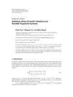
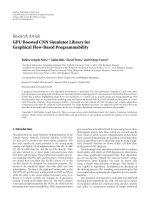
Figure 1 shows a photograph of the Helios board, measuring
6.5cm
9 cm and weig hing just 37 g. Resources on the board
include the Virtex-4 FX FPGA chip, multiple types of mem-
ory, a collection of connectors for I/O, and a small number
of switches, buttons, and LEDs.
4.1. Modular design
The Helios board is designed to be the main computational
engine for a variety of applications, but by itself is not suffi-
cient for stand-alone operation in most vision-based appli-
cations. For example, Helios includes neither a camera nor
the camera interface features that one might expect given
the target applications. The base functionality of the board is
extended by connecting one or more stackable, application-
specific daughter boards via a 120-pin header.
This design approach allows the main board to be used
without modification for applications that vary widely in the
sensors and actuators they require. Since daughter boards
consist mainly of connectors to devices and are much less
Figure 1: The Helios board.
complex than the Helios board, it is less costly to create a
custom daughter board for each application than to redesign
and fabricate a single board incorporating all components. A
consequence of our design philosophy is that little about He-
lios is specific to vision applications; its resources for compu-
tation, storage, and I/O are well matched for general applica-
tions.
The use of vertically stacking daughter boards also helps
Helios meet the critical size constraints of our target appli-
cations. A single board comprising all necessary components
for the system would generally be too large. In contrast, He-
lios only increases in size vertically by a small amount with
each additional daughter board.
Several daughter boards have been designed and used
with Helios, such as a custom daughter board for small,
ground-based vehicles and a camera board for use with
very small CMOS image sensors. The ground-based vehicle
board, for example, is ideal for use on small (e.g., 1/10 or 1/12
scale) R/C cars. It includes connectors for two CMOS image
sensors, a wireless transceiver, an electronic compass, servos,
an optical encoder, and general-purpose I/O.
4.2. Component detail
The most significant features of the board are summarized in
this section.
Xilinx Virtex-4 FPGA
The Virtex-4 FX series of FPGAs includes both reconfig-
urable logic resources and low-power PowerPC processor
cores on the same die, making these FPGAs ideal for em-
bedded processing. At the time of writing, this 90 nm FPGA
represents the state of the art in performance and low-power
consumption. Helios can be populated with any of three FX
platform chips, including the FX20, FX40, and FX60. These
FPGAs differ in available logic cells (19 224 to 56 880), on-
chip RAM blocks (1224 to 4176 Kbits), and the number of
PowerPC processor cores (1 or 2). These PowerPC processors
W.S.FifeandJ.K.Archibald 5
can operate up to 450 MHz and include separate data and
instruction caches, each 16 KB in size, for improved perfor-
mance.
Memor y
Helios includes different types of memory for different pur-
poses. The primary memory for program code and data is
a synchronous DRAM or SDRAM. The design utilizes low-
power 2.5 V mobile SDRAM that can operate up to 133 MHz.
Helios accommodates chips that provide a total SDRAM ca-
pacity ranging from 16 to 64 MB.
Helios also includes a high-speed, low-power SRAM that
can serve as an image buffer or a fast program memory. A 32-
bit ZBT (zero bus turnaround) device is employed that can
operate up to 200 MHz. Depending on the chip selected, the
SRAM capacity ranges from 1 to 8 MB.
For convenient embedded operation, Helios includes
from 8 to 16 MB of flash memory for the nonvolatile storage
of program code and initial data.
Finally, Helios includes a nonvolatile Platform Flash
memory used to store configuration information for the
FPGA on power-up. The Platform Flash ranges in size from
8 to 32 Mbit. This flash can store multiple FPGA configura-
tions as well as software for boot loading.
I/O connectors
Helios includes a high-speed USB 2.0 interface that can be
powered either from the USB cable or the Helios board’s
power supply. The USB connection is particularly u seful for
transferring image data off-board during algorithm develop-
ment and debugging. The board also includes a serial port. A
standard JTAG port is included for FPGA configuration and
debugging, PowerPC software debugging, and configuration
of the Platform Flash. Finally, a 120-pin header is included
for daughter board expansion. This header provides power
as well as 64 I/O signals for the daughter boards.
Buttons, switches, and LEDs
The system includes switches for FPGA mode and configu-
ration options, a power indicator LED, and an FPGA pro-
gram button that causes the FPGA to reload its configura-
tion memory. Additionally, Helios includes two switches, two
buttons, and two LEDs that can be used as desired for the ap-
plication.
4.3. Design tradeoffs
As previously noted, alternative techniques can be employed
to support on-board vision processing. Conceivable op-
tions range from conventional processors (e.g., embedded,
desktop, DSP) to custom silicon chips. The latter is imprac-
tical for low-volume applications largely because of high de-
sign and testing costs as well as extremely high nonrecurring
engineering (NRE) costs needed for chip fabrication.
There are several advantages and disadvantages of the
FPGA-based approach used in Helios when compared to
pure software designs and custom chips. Let us consider sev-
eral interrelated topics that are critical in the applications tar-
geted by Helios.
(i) Computational performance
In the absence of custom logic to accelerate computation,
performance is essentially reduced to the execution speed of
standard compiled code. For FPGAs, this depends on the ca-
pabilities of the processor cores employed. Generally, the per-
formance of processor cores on FPGAs compares fa vorably
with other embedded processors, but falls short of that typi-
cally delivered by desktop processors.
When custom circuitry is considered, FPGA performance
can usually match or surpass that of the fastest desktop pro-
cessors since the design can be custom tailored to the com-
putation. The degree of performance improvement depends
primarily on how well the computation maps to custom
hardware.
One of the primary benefits of Helios is its ability to in-
tegrate software execution with custom hardware execution.
In e ffect, Helios provides the best of both worlds. Helios har-
nesses the ease of use provided by software but allows the
integration of custom hardware as needed in order to meet
real-time performance constraints.
(ii) Power consumption
FPGAs are usually considered to have high-power consump-
tion. This is mostly due to the fact that a custom sili-
con chip will always be able to perform the same task
with lower power consumption and the fact that many em-
bedded processors require less peak power. However, these
facts are largely misunderstood. One must also consider the
power-performance ratio of various alternatives. For exam-
ple, the power-performance ratio of FPGAs is often excel-
lent when compared to general-pur pose central processing
units (CPUs), which are very power inefficient for many
processing-intense applications.
Many embedded processors require less power than He-
lios, but low-power chips rarely offer comparable perfor-
mance. As the clock frequency and performance of embed-
ded processors increase, so does the power consumption.
For example, Gwennap compared the CPU costs and typi-
cal power requirements of seven embedded processors with
clock rates between 400 and 600 MHz [22]. The power con-
sumption reported for these embedded CPUs ranged from
0.5to4.0W.
In our experience, power consumption of the Helios
board is typically around 1.25 W for designs running at
100 MHz. Of course, FPGA power consumption is highly de-
pendent on the clock speed and the design running on the
FPGA. Additionally, clock speed, by itself, is not a meaning-
ful measure of performance. Still, Helios and FPGA-based
systems in general compare very favorably in this regard to
desktop and laptop processors.
6 EURASIP Journal on Embedded Systems
We contend that current FPGAs can be competitive re-
garding power consumption, particularly when comparing
platforms that deliver comparable performance.
(iii) Cost
Complex, high-p erformance FPGA parts can be expensive.
Our cost per chip for the Virtex-4 FX20 at this writing is
$236, for quantities less than ten. Obviously, this price will
fluctuate over time as a function of volume and competition.
This is costly compared to typical embedded processors, but
within the price range of desktop CPUs.
Clearly, a fair comparison of cost should consider per-
formance,butthisismoredifficult than it sounds because
FPGAs deliver their peak p erformance in a fundamentally
different way than conventional processors. As a result, it is
difficult to find implementations of the same application for
objective comparison.
FPGA costs are favorable compared to custom chip de-
sign in low-volume markets. The up-front, NRE costs of cus-
tom chip fabrication are so expensive that sales must often be
well into thousands of units for it to make economic sense.
For all platforms, the cost increases with the level of p er-
formance required. Although it does not completely com-
pensate for the costs, it should be noted that the same FPGA
used for computation can also integrate other devices and
provide convenient interfacing to sensors and actuators, thus
reducing part count.
(iv) Flexibility
In this category, FPGAs are clear winners. In the case of He-
lios, the same hardware can be used to support a variety of
application-specific designs. On-chip processor cores allow
initial development identical to that of conventional embed-
ded processors: write the algorithm in a high-level language,
compile, and execute. Once this is shown to work correctly,
performance c an be dramatically improved by adding cus-
tom hardware. This added level of performance tuning is un-
available on conventional processors with fixed instruction
sets and hardware resources. Particularly noteworthy is the
possibility of adding additional processor or DSP cores in-
side the FPGA to increase performance through parallel exe-
cution. As the FPGA design develops or as needs change, the
design can be easily modified and the FPGA can be reconfig-
ured with the new design.
(v) Ease of use
Since one cannot obtain their best performance by simply
compiling and tuning standard code, FPGAs are more diffi-
cult to use effectively than general purpose processors alone.
The quality of design tools is improving, but the added
overhead of designing custom hardware blocks—or merely
integrating a system from existing core components—is sub-
stantial relative to that of modifying functionality in soft-
ware. Moreover, FPGA design tools are more complex, have
longer run times, and are more difficult to use than standard
compilers.
On the other hand, FPGA development is much less in-
volved than custom chip design. An FPGA design can be
modified and the FPGA reconfigured in a matter of minutes
instead of the weeks required to fabricate a new chip. Addi-
tionally, an FPGA design revision does not incur the expen-
sive costs of fabricating an updated chip design.
Debugging of FPGA designs is also much easier than the
debugging of a custom chip. With the help of debug tools,
such as on-chip logic analyzers, designers can see exactly
what is happening inside the FPGA while it is running. Or
the FPGA can be reconfigured with custom debug logic that
can be removed later. Such tools provide a level of visibility
that is usually not available on custom chips due to the
implementation costs.
The tradeoffs between these important criteria are such
that there is no clear winner across the entire design space;
all approaches have their place. For our applications, it was
imperative that the design be flexible, that it provide high
performance, and—within these constraints—that it be as
power efficient as possible. With these goals in mind, the
choice of FPGAs was clear.
5. DESIGN EXAMPLE: 3D RECONSTRUCTION
In this section, we describe the FPGA-based implementation
of a challenging vision problem for small robots, namely,
the creation of a 3D map of the surrounding environment.
While no s ingle example can represent all facets of interest
in vision-based applications, our experience implementing a
3D reconstruction algorithm on Helios provides valuable in-
sight into the suitability of FPGAs for real-time implemen-
tations of vision algorithms. It also gives an indication of
the design effortrequiredtoobtainreal-timeperformance.
The example system described in this section uses Helios to
perform real-time 3D reconstruction from 320
240, 8-bit
grayscale images, running at over 30 frames per second.
It should be noted that this is just one example of the
many kinds of systems that can be implemented on Helios.
Because of its reconfigurability, Helios has been used for a
variety of machine vision applications as well as video pro-
cessing applications. Additionally, we do not claim that the
particular implementation to be described gives the highest
computational per formance possible. Instead, it is intended
to show that the objective of real-time, 3D reconstruction can
be achieved using a relatively low amount of custom hard-
ware in a small, low-power system. We begin with a discus-
sion of techniques used to obtain spatial information from
the operating environment.
5.1. Extracting spatial information
One of the essential capabilities of an autonomous vehi-
cle is the ability to generate a map of its environment for
navigation. Several techniques and sensor types have been
used to extract this kind of information; the most popular
of these for mobile robots are sonar sensors and laser range
finders [23]. These active sensors work by transmitting sig-
nals (i.e., sound or laser light), then sensing and processing
W.S.FifeandJ.K.Archibald 7
the reflections to extract information about the environment.
On-board vision has also been used for this purpose and
offers certain advantages. First, image sensors are passive,
meaning that they do not need to transmit signals in order to
sense their environment. Because they are passive, multiple
vision systems can operate in close proximity without inter-
fering with one another and the sensor system is more covert
and difficult to detect, an important consideration for some
applications. Visual data also contains a lot of additional in-
formation, such as colors and shapes that can be used to clas-
sify and identify objects.
Two basic configurations have been used for extracting
spatial information from a vision system. The first, stereo vi-
sion, employs two cameras spaced slightly apart. This con-
figuration works by identifying a set of features in the im-
ages from both cameras and using the disparity (or distance)
between features in the two images to compute the distance
from the cameras to the feature. This method works because
distant objects have a smaller disparity than nearby objects.
A variant of stereo vision, called trinocular vision, uses three
cameras in a right triangle arrangement to obtain better re-
sults [15].
A second approach uses a single camera that moves
through the environment, presumably mounted on a mo-
bile platform, such as a small vehicle. As the camera moves
through the environment, the system monitors the motion
of features in the sequence of images coming from the cam-
era. If the velocity of the vehicle is known, the rate of motion
of features in the images can be used to extract spatial infor-
mation. This method works because distant objects change
more slowly than nearby objects in the images as the camera
moves. However, it works well only in static environments
where objects within the camera’s view are stationary.
5.2. Autonomous robot platform
In order to demonstrate the power of FPGAs in small, em-
bedded vision systems, we created an FPGA-based, mobile
robot that uses a single camera to construct a 3D map of
its environment and navigate through it (for a related im-
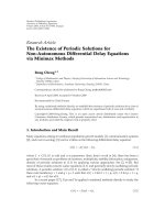
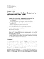
plementation, see our previous work [24]). The autonomous
robot hardware used for our experiments consisted of a small
(17 cm
20 cm), two-wheeled vehicle, shown in Figure 2.
The hardware included optical wheel encoders in the motors
for precise motion control and a small, wireless transceiver
to communicate with the robot.
For image capture we connected a single Micron MT9-
V111 CMOS camera to capture images at a rate of 15 to 34 fps
with an 8-bit grayscale, 320
240 resolution.
The Helios board used to test the example digital system
was built with the Virtex-4 FX20 FPGA (
10 speed g rade),
1 MB SRAM, 32 MB SDRAM, 16 MB flash, and a 16 Mbit
Platform Flash. We also used a custom daughter board that
allowed us to connect to the external devices, such as the dig-
ital camera and wireless transceiver.
Using Helios as the computational hardware for the sys-
tem results in tremendous flexibility. The FPGA development
tools allow us to easily design and implement a complete sys-
Figure 2: Prototype robot platform.
tem including all the peripherals needed for our application.
Specifically, we used the Xilinx Embedded De velopment Kit
(EDK) in conjunction with the Xilinx ISE tools to develop
our system.
For this application we used the built-in PowerPC pro-
cessor as well as several peripheral cores, including a floating
point unit (FPU), a UART, memory controllers, motor con-
trollers, and a camera interface. All of these devices are im-
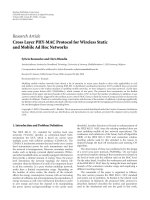
plemented on the FPGA. Figure 3 shows the essential com-
ponents of our example system and their interconnection.
The most commonly used peripherals are included in the
EDK as intellectual property (IP) cores that can be easily in-
tegrated into the system. This includes all of the basic digital
devices normally expected on an embedded microcontroller.
In addition, these IP cores often include high-performance
features not available on many microcontrollers, such as 64-
bit data transfers, direct memory access (DMA) support for
bus peripherals, burst mode bus transactions, and cache-
line burst support between the PowerPC and memory con-
trollers. Additionally, these cores are highly configurable, al-
lowing them to be customized to the application. For exam-
ple, if memory burst support is not needed on a particular
memory, it can be disabled to free up FPGA resources.
In addition to standard IP cores, we also integrated our
own cores. For this example system, we designed the motor
controller core, the camera interface core, and the floating-
point unit. T he end result is a complete system on a pro-
grammable chip. All processing and control are perfor med
on the FPGA, the most significant portion of the image pro-
cessing being performed in the camera interface core.
5.3. 3D reconstruction
The vision algorithm implemented on Helios for this exam-
ple works by tracking feature points through a sequence of
images captured by the camera. For each image frame, the
system must locate feature points that were identified in the
previous frame and update the current estimate of each fea-
ture’s position in 3D world space. The 3D reconstruction al-
gorithm can be divided into two steps performed on each
8 EURASIP Journal on Embedded Systems
Virtex-4 FX20 FPGA
Off-chip
SRAM
Memory
controller
Block RAM
PowerPC
processor
FPU
Reset
controller
Clock
managers
JTAG
interface
JTAG
port
64-bit processor local bus (PLB)
OPB to PLB
bridge
PLB to OPB
bridge
32-bit on-chip peripheral bus (OPB)
Camera
core
Motor
controllers
UART
CMOS
camera
Motor
ports
Wireless
module
Figure 3: System diagram of example system.
frame: feature tracking and spatial reconstruction. We de-
scribe each in turn.
5.3.1. Feature tracking
In order to track features through a sequence of images, we
must first identify the features to be tracked. A feature, in this
context, is essentially a corner of high contrast in the image.
Any pixel in an image could potentially be a feature point.
We can evaluate the quality of a candidate pixel as a feature
using Harris’ criterion [25]:
C(x)
= det(G)+k trace
2
(G). (1)
Here G is a matrix computed over a small window, W(x),
of pixels (7
7 in our implementation), x is the vector coor-
dinate of the pixel to evaluate, and k is a constant chosen by
the designer. Our 7
7 window size was selected experimen-
tally after trying several window sizes. The matrix G is given
by the following equation:
G
=
⎡
⎢
⎢
⎢
⎣
W(x )
I
2
x
W(x )
I
x
I
y
W(x )
I
x
I
y
W(x )
I
2
y
⎤
⎥
⎥
⎥
⎦
. (2)
Here I
x
and I
y
are the gradients (or image derivatives)
obtained by convolving the image with a pair of filters. These
image derivatives require a lot of computation and are com-
puted in our custom camera core, described in Section 5.4.3.
With the derivatives computed, the initial features to track
are then selected based on the value of C(x), as described by
Ma et al. [26].
Once the initial features have been selected, we track each
feature individually across the sequence of image frames as
they are received in real time from the camera. Many sophis-
ticated techniques have been proposed for tracking features
in images [27–29]. Our system uses a simple approach where
the pixel w ith the highest Harris response in a small window
around the prev ious feature location is selected as the fea-
ture in the current frame. This method works quite well in
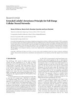
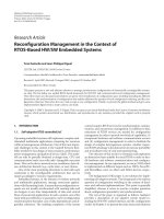
the environment where the system was tested. Figure 4 shows
the feature tracking results obtained by the system as it ap-
proaches a diamond-patterned wall. Twenty-five frames with
tracked features fall between each of the frames shown. T he
feature points being tracked are highlighted by small squares.
Note that most of the diamond vertices were identified as
good features and are therefore highlighted.
5.3.2. Spatial reconstruction
The feature tracking algorithm described provides us w ith
the 2D image coordinates of features tracked in a series of
images as the robot moves through its environment. When
combined with accurate information about the robot’s mo-
tion, we can determine the 3D world coordinates of these fea-
tures. The motors in our prototype robot include built-in en-
coders that give precise position feedback. The custom motor
controller core on the FPGA monitors the encoder output to
track each wheel’s motion. This allows us to determine and
control the robot’s position with submillimeter accuracy.
One method to obtain the 3D reconstruction is derived
directly from the ideal p erspec tive projection, based on an
ideal camera model with focal length f . It is described by the
equations
x
= f
X
Z
, y
= f
Y
Z
. (3)
Here, (x, y) is the pixel coordinate of a feature in the cam-
era image, with the origin at the center of the image. This
pixel location corresponds to the projection of a real-world
feature onto the camera’s image plane. The location of the
W.S.FifeandJ.K.Archibald 9
(a)
(b)
(c)
Figure 4: Features tracked in the captured images.
Y
y
f
Z
Camera
Feature
projection
Image
plane
Feature
Figure 5: Camera model.
actual feature in 3D world space is (X, Y , Z), w here the cam-
era is at the origin, looking down the positive Z-axis. A side
view of this model is shown in Figure 5.
As the robot moves forward, the system monitors the dis-
tance of the feature’s (x, y) coordinate from the optical center
of the camera. This distance increases as the robot moves to-
wards the feature.
The situation after the robot has moved forward some
distance is shown in Figure 6. Knowing the forward distance
(D ) the robot has moved and the distance the feature has
moved in the image (e.g., from y to y
) allows us to estimate
Y
y
y
f
Z
Z
D
Camera
Image
plane
Feature
Figure 6: Camera model after forward motion.
the horizontal distance (Z ) to the feature using principles of
geometry.
From Figure 6 we can see that the following equations
hold:
Y
Z
=
y
f
,
Y
Z
=
y
f
,
Z
= Z + D.
(4)
From these equations, we can derive an equation for Z
:
Z
= Y
f
y
= Z
Y
Z
f
y
= Z
y
f
f
y
= (Z + D)
y
y
. (5)
Solving for Z
, we obtain the desired distance
Z
=
D y
y y
. (6)
Once distance Z
is known, we can easily solve for the X
and Y coordinates of the feature point in world s pace.
Figure 7 shows a rendering of the 3D reconstruction gen-
erated by the system while running on a robot moving to-
wards the flat wall shown in Figure 4. The object on the left
side of the figure indicates the position of the camera. The
spheres on the right show the perceived position of tracked
feature points in world space, as seen by the system. Only
points within the camera’s current field of view are shown. As
can be seen from the figure, the spheres sufficiently approx-
imate the flat surface of the wall. With this information and
its artificial intelligence code, the robot prototype was able
to determine the distance to obstacles and navigate around
them.
5.4. Hardware acceleration
The complex image processing required by vision systems
has limited their use, especially in embedded applications
with strict size and power requirements. In our example sys-
tem, the process of computing the image derivative values
(I
x
and I
y
), tracking features, and calculating the 3D position
10 EURASIP Journal on Embedded Systems
Figure 7: Rendering of the robot’s perceived environment. The
spheres show the perceived 3D positions of feature points tracked
on the wall of Figure 4.
of each tracked feature must be performed for each frame
that comes from the camera, in addition to the motor con-
trol and artificial intelligence that must execute concurrently.
To complicate matters, this must be performed in real time,
meaning that the processing of one frame must be completed
before the next frame is received from the camera.
To meet these performance requirements, the system had
to be partitioned among custom hardware cores in addition
to traditional software running on the PowerPC. Two forms
of custom hardware were employed in this system: a float-
ing point unit and an image derivative processor. The FPU
is used extensively to obtain precise results in the software
feature selection and 3D reconstruction algorithms described
in Section 5.3. The image derivative processor automatically
computes the values in I
x
and I
y
as images are received from
the camera, relieving the CPU of this significant computa-
tion.
5.4.1. Floating point unit
Arguably, most image processing computation could be per-
formed using very efficient fixed point arithmetic. In most
cases, using fixed point will reduce power consumption and
increase performance. Yet it has its disadvantages. First, man-
aging precision in complicated fixed point arithmetic is time
consuming and error prone. Second, fixed point ar ithmetic
can be particularly cumbersome in situations where a large
dynamic range is required. Use of floating point greatly eases
the job of the programmer, allowing one to create reliable
code in less time. In our case, use of floating point in addi-
tion to fixed point not only eases development of our system’s
software, it demonstrates the great flexibility available to re-
configurable systems.
An option not available on many microcontrollers, an
FPU can be easily added to an FPGA design as an IP core.
Additionally, the microprocessor cores used in FPGAs typi-
cally have high-speed interfaces to the FPGA fabric which are
ideally suited to interfacing coprocessor cores such as FPUs.
For example, the Xilinx MicroBlaze soft processor core can
use fast simplex links (FSL) to connect a coprocessor directly
to the processor. The PowerPC 405 embedded processor core
Table 1: Performance of 100 MHz FPU compared to software em-
ulation. All cycle latencies are measured by the PowerPC’s 300 MHz
clock.
Operation FPU cycles Software cycles Speedup
Add 26 195 7.5
Sub 26 210 8.1
Mult 30 193 6.4
Div 60 371 6.2
Compare 23 134 5.8
Sqrt 60 1591 26.5
Itof 23 263 11.4
available on the Virtex-4 FX features the auxiliary proces-
sor unit (APU) which allows a coprocessor core to inter-
face directly with the PowerPC’s instruction pipeline. Using
the APU interface, the PowerPC can execute genuine Pow-
erPC floating point instruc tions or user defined instructions
to perform custom computation in the FPGA fabric. In our
system, we used this APU interface to connect our FPU di-
rectly to the PowerPC, enabling hardware execution of float-
ing point instructions.
Our custom FPU is based on the IEEE standard 754 for
single precision floating point [30]. However, our FPU is
highly configurable so that it can be retargeted to run at var-
ious clock rates. For example, the FPU adder module can be
configured to have a latency from one cycle to nine cycles,
giving it a corresponding operating frequency range from
35 MHz to 200 MHz in our system. The FPU can also be con-
figured to support any combination of add, subtract, float to
int, int to float, compare, multiply, divide, and square root,
with more FPGA resources being required as the number
of supported operators increases. In order to further con-
serve FPGA resources, the FPU does not support +/
NaN,
+/
INF, denormalized numbers, or extra rounding modes.
5.4.2. FPU performance
Compared to software emulation of floating point opera-
tions running at 300 MHz on the PowerPC, the FPU running
at only 100 MHz provided significant performance improve-
ment. The speedup ranged from about 6 for comparison op-
erations up to 26 for square root. The poor performance of
the square root in software is partly due to the fact that the
standard math library computes the square root using double
precision floating point.
Table 1 shows the speedup obtained for various floating
point operations compared to software emulation. Note that
the number of cycles given for floating point operations is
measured by the PowerPC’s 300 MHz clock, allowing easy
comparison between the FPU core and software emulation.
Table 2 shows the FPGA resources required for various float-
ing point configurations. The FPU multiplier also requires
the use of four hardware multipliers built into the FPGA.
The 1368-slice configuration represents the configura-
tion used in our exper iments and can run at over 100 MHz
on a
10 speed grade Virtex-4 FX20. With full pipelining
W.S.FifeandJ.K.Archibald 11
Table 2: FPGA resources consumed by the FPU. The percentage
of resources used is based on the number of slices available on the
Virtex-4 FX20.
Slices % Resources Configuration
403 4% Add, sub, mult, no pipelining
549 6% Add, sub, mult, partial pipelining
1078 12% All operations, no pipelining
1368 16% All operations, partial pipelining
1515 17% All operations, full pipelining
enabled, the full FPU can run at over 150 MHz on the 12
speed grade FPGA.
Interestingly, we found that measurements of power con-
sumption on Helios actually went down slightly during heavy
FPU usage, not up as we expected. We believe that this is due
to the fact that the CPU becomes t ruly idle (i.e., the pipeline
is stalled) while waiting for the FPU to return its results.
5.4.3. Image derivative computation
The image derivative computations used to generate I
x
and
I
y
, which consist of two 2D convolutions over the entire
image, require significant computation. The image deriva-
tives are computed by applying a matrix kernel to the region
around each pixel. To put this into perspective, a 3
3ker-
nel requires up to 9 multiplications, 8 additions, and 1 divide
when applied to the 3
3 region around a pixel, depending
on the kernel and normalization used. With a 320
240 im-
age resolution, as used in our system, this derivative com-
putation must be applied to the 3
3regionaroundall
318
238 = 75 684 pixels (the edge pixels are excluded
from the computation). Finally, this computation must be
performed twice per image, once for the x direction and
once for the y direction. Thus, each frame requires up to
(9 + 8 + 1)
75 684 2 = 2 724 624 arithmetic computa-
tions. At 30 fps this requires nearly 82 million computations
per second. Combine this with memory access latencies and
the fact that multiplication and division are typically multi-
cycle operations and it becomes clear that this kind of com-
putation is simply out of reach for most small embedded pro-
cessors. A 640
480 image resolution would require over 329
million arithmetic operations per second with the same ker-
nel.
In our example system, the image derivatives are calcu-
lated entirely in the custom camera core. Within the cam-
era core is a module, called the Pixel Processor, that com-
putes the image derivatives in real time as the images are re-
ceived from the camera. Because we are using custom hard-
ware, we are able to take advantage of significant parallelism
when performing this computation. For example, the hard-
ware is capable of p erforming all nine multiply operations
in parallel and uses adder trees to parallelize the addition
operations. The hardware is also pipelined so that multipli-
cations and additions operate concurrently. Running at less
than 75 MHz, the system is able to perform the computation
for 320
240 images received at a rate of 30 fps. A block dia-
gram of the Pixel Processor core is shown in Figure 8.
Traditionally, the convolution operation used to generate
I
x
and I
y
can take up significant FPGA resources. However,
advances in FPGA performance and the advent of built-in,
high-speed RAM blocks (called block RAM or BRAM) al-
low for implementations requiring significantly reduced re-
sources.
The process begins in the Pixel Processor module as pix-
els are received on the pixel input. The camera transfers im-
age pixels from left to right, row by row, starting with the
upper-left image pixel. Each pixel is immediately fed into the
RAM Write unit. The RAM Write unit then buffers the pixels
in a high-speed, dual-port BRAM built into the FPGA fabric.
Once three rows of the image have been buffered, enough
data has been received to begin applying the 3
3 kernel and
generate the first row of I
x
and I
y
. At this point, the Pixel
Counter unit signals the RAM Read unit to begin reading out
the first 3
3 set of pixels necessary to apply the 3 3kernel.
These nine pixel values are then fed into the Derivative unit,
which perform s the derivative computations and outputs the
I
x
and I
y
values. These I
x
and I
y
values are subsequently fed
into the DMA Control unit, along with the original image
pixel value, where they a re automatically written to external
SRAM for later use by the FPGA’s CPU. This process immedi-
ately repeats itself for the 3
3 region around the next pixel.
While the derivative computations are being performed for
the current row, new pixel values for the next row are being
buffered simultaneously in the dual-port BRAM.
5.4.4. Image derivative performance
By taking advantage of the BRAMs built into the FPGA, the
Pixel Processor core (excluding the FIFOs and DMA con-
troller) consumes only 234 slices and 1 BRAM of the FPGA.
This represents less than 3% of the FPGA resources of our
Virtex-4 FX20. Given our 320
240 resolution and 30 fps
frame rate, we found that 75 MHz was sufficient for com-
putation of the image derivatives in real time. However, the
Pixel Processor core could run at over 240 MHz on the same
FPGA.
The only real latency penalty is the delay required to
buffer the first three rows of image data. At 320
240, this
represents only 1.25% of the frame time. This latency could
be further reduced by buffering only the first two rows plus
the first two pixels of the third row. Once this is done, the
derivative computation could be performed as soon as each
new pixel is received.
This simple architecture is not only adequate for per-
forming this computation in real time but it leaves headroom
for higher resolutions as well as different or larger kernels.
For example, increasing the size of the kernel is a simple mat-
ter of updating the RAM Read unit and changing the Deriva-
tive unit to apply the new kernel. Or, if a kernel of the same
size with different values is desired, only the Derivative unit
needs to be updated. Further performance increases can be
obtained by using alternative architectures and more hard-
ware resources in the FPGA to increase parallelism. This kind
12 EURASIP Journal on Embedded Systems
Pixel processor
Dual-port
BRAM
Pixel
matrix
Addr
Data
Addr
Data
RAM
write
RAM
read
Derivative
I
x
I
y
FIFO
FIFO
FIFO
DMA
control
DMA addr
DMA data
Done
Pixel
valid
Pixel
New
frame
Start
row
Pixel
counter
New
frame
Figure 8: Pixel processor block.
Table 3: Helios power consumption during image processing.
Power (W)
FPGA speed CPU speed Camera rate
(MHz) (MHz) (fps)
1.17 75 75 15
1.27 75 75 34
1.33 100 300 15
1.39 100 300 34
of flexibility mirrors that of software, but the performance is
comparable to that of custom hardware.
5.5. Resource utilization and power consumption
Our entire example system (as shown in Figure 3) uses only
4589 slices, or about 53% of the Virtex-4 FX20 FPGA. This
leaves room for more sophisticated image processing or im-
proved performance through more parallelization.
Power consumption of Helios is highly dependent on the
FPGA utilization, clock frequency, CPU state, and the state
of other FPGA circuitry. Table 3 reports the combined power
consumption of the entire Helios board and the CMOS
camera circuitry. These numbers were measured during ac-
tive image processing and storage in external SRAM using
the example system. We have found these numbers to be
fairly representative of many of the medium-sized designs for
which Helios has been employed.
6. BENEFITS OF RECONFIGURABILITY
The importance of reconfigurability in our 3D reconstruc-
tion system, as well as any other application involving He-
lios, cannot be overemphasized. Because our system is recon-
figurable we are able to test, in real-word situations, a wide
variety of implementation parameters. Custom debug hard-
ware can be added to aid in the debug process then removed
as needed. At our discretion we can expand the functionality
of a given system or change it in dramatic ways without hav-
ing to physically modify the Helios board. All that is needed
is to synthesize the new design and reconfigure the FPGA.
This reconfigurability was exploited throughout the develop-
ment, debugging, and testing of our 3D reconstruction ex-
ample system.
The flexibility provided by reconfigurability allows us to
use the same physical board for a wide variety of applica-
tions and implementations. In low production volume ap-
plications, such as research and many vision applications, the
small fixed cost of FPGAs is significantly less than the fabri-
cation costs of an equivalent silicon design. Yet, FPGAs can
deliver superb performance, low-power consumption, and a
very small system size when compared to the computer re-
quired for a software-only implementation. These benefits
make FPGA-based platforms an excellent choice for embed-
ded vision applications.
7. CONCLUSIONS
Embedded vision systems have significant performance de-
mands and often have strict size and power constraints. In
this paper, we have shown that FPGAs can be used effec-
tively in supporting real-time vision processing, even in set-
tings where size and power are significant concerns. In fact,
the considerable resources available on current FPGAs can be
utilized to achieve very high levels of performance in small
systems.
We have also introduced Helios, a small, FPGA-based
circuit board intended for use in small UAVs and ground-
based robots to provide on-board vision processing. Helios
takes full advantage of the reconfigurable nature of FPGAs
to provide high levels of flexibility and performance while
maintaining moderate levels of power consumption. These
characteristics make Helios ideally suited to the substantial
processing demands of embedded vision systems.
W.S.FifeandJ.K.Archibald 13
This paper also descr ibed a detailed example where He-
lios has been used: 3D reconstruction of an environment us-
ing a single camera. This example gives insight into the flexi-
bility of the platform, the manner in which algorithms can be
implemented on such a platform, and the performance that
can be realized. Yet, Helios has been used in a variety of other
applications beyond this design example.
Helios is currently being used in the development of tar-
get tracking algorithms for small UAVs. It is also being used
as the computational platform for a small four-rotor aircraft
currently under development. It has been successfully used as
the complete processing platform for vision guided ground
vehicles based on a 41 cm long, off-road truck. These trucks
were used in a student competition to autonomously navi-
gate a racetrack. Helios has also been used in the develop-
ment of image processing algorithms for standard-definition
video. Each of these applications has employed a combina-
tion of custom hardware and software to support a wide
range of machine vision algorithms. This breadth shows the
possibilities for a reconfigurable robotic vision platform.
Work on these projects wil l continue and we expect that
many more opportunities for a small reconfigurable system
such as Helios will present themselves. In particular, we feel
that the use of Helios on small UAVs will continue to ex-
pand. In this environment, where the demanding balance
between size, weight, power consumption, and processing
performance must be maintained, reconfigurable hardware
is proving to be an excellent match. As FPGA technology and
development tools continue to improve, we fully expect FP-
GAs to become increasingly well suited to embedded vision
applications.
REFERENCES
[1] G.N.DeSouzaandA.C.Kak,“Visionformobilerobotnav-
igation: a survey,” IEEE Transactions on Pattern Analysis and
Machine Intelligence, vol. 24, no. 2, pp. 237–267, 2002.
[2] R . Beard, D. Kingston, M. Quigley, et al., “Autonomous ve-
hicle technologies for small fixed-wing UAVs,” AIAA Jour-
nal of Aerospace Computing, Information, and Communication,
vol. 2, no. 1, pp. 92–108, 2005.
[3] A. Georgiev and P. K. Allen, “Localization methods for a
mobile robot in urban en vironments,” IEEE Transactions on
Robotics, vol. 20, no. 5, pp. 851–864, 2004.
[4] J. M. Saez and F. Escolano, “A global 3D map-building ap-
proach using stereo vision,” in Proceedings of IEEE Interna-
tional Conference on Robotics and Automation (ICRA ’04),
vol. 2, pp. 1197–1202, New Orleans, La, USA, April 2004.
[5] F. Ruffier and N. Franceschini, “Visually guided micro-aerial
vehicle: automatic take off, terrain following, landing and
wind reaction,” in Proceedings of IEEE International Conference
on Robotics and Automation (ICRA ’04), vol. 3, pp. 2339–2346,
New Orleans, La, USA, April 2004.
[6] G. Cheng and A. Zelinsky, “Real-time visual behaviours for
navigating a mobile robot,” in Proceedings of IEEE Interna-
tional Conference on Intelligent Robots and Systems (IROS ’96),
vol. 2, pp. 973–980, Osaka, Japan, November 1996.
[7] M. M. Chang, B. Browning, and G. Wyeth, “ViperRoos: devel-
oping a low cost local vision team for the small size league,”
in RoboCup 2001: Robot Soccer World Cup V, pp. 305–311,
Springer, Berlin, Germany, 2002.
[8] T. Br
¨
aunl and B. Graf, “Autonomous mobile robots with on-
board vision and local intelligence,” in Proceedings of the 2nd
IEEE Workshop on Perception for Mobile Agents, Fort Collins
(WPMA-2 ’99), pp. 51–57, Colorado, Colo, USA, June 1999.
[9] S. Mahlknecht, R. Oberhammer, and G. Novak, “A real-
time image recognition system for tiny autonomous mobile
robots,” in Proceedings of IEEE Real-Time and Embedded Tech-
nology and Applications Symposium (RTAS ’04), vol. 10, pp.
324–330, Toronto, Canada, May 2004.
[10] T. Smith, “Adding vision to Khepera: an autonomous robot
footballer,” M.S. thesis, University of Sussex, Sussex, UK, 1997.
[11] P. Bertin, D. Roncin, and J. Vuillemin, “Introduction to pro-
grammable active memories,” Tech. Rep. PRL-RR-3, DEC
Paris Research Laboratory, Paris, France, 1989.
[12] S. Hirai, M. Zakouji, and T. Tsuboi, “Implementing image pro-
cessing algorithms on FPGA-based realtime vision systems,” in
Proceedings of the 11th Workshop on Synthesis and System Inte-
gration of Mixed Information Technologies (SASIMI ’03),pp.
378–385, Hiroshima, Japan, April 2003.
[13] S. McBader and P. Lee, “An FPGA implementation of a flexible,
parallel image processing architecture suitable for embedded
vision systems,” in Proceedings of the 17th IEEE International
Symposium on Parallel and Distributed Processing (IPDPS ’03),
p. 228, Nice, France, April 2003.
[14] A. Darabiha, J. Rose, and W. J. MacLean, “Video-rate stereo
depth measurement on programmable hardware,” in Proceed-
ings of the IEEE Computer Society Conference on Computer Vi-
sion and Pattern Recognition, vol. 1, pp. 203–210, Madison,
Wis, USA, June 2003.
[15] Y. Jia, X. Zhang, M. Li, and L. An, “A miniature stereo vision
machine (MSVM-III) for dense disparity mapping,” in Pro-
ceedings of the 17th IEEE International Conference on Pattern
Recognition (ICPR ’04), vol. 1, pp. 728–731, Cambridge, UK,
August 2004.
[16] S. C. Wong, M. Jasiunas, and D. Kearney, “Towards a reconfig-
urable tracking system,” in Proceedings of IEEE International
Conference on Field Programmable Logic and Applications (FPL
’05), pp. 456–462, Tampere, Finland, August 2005.
[17] H. Yamada, T. Tominaga, and M. Ichikawa, “An autonomous
flying object navigated by real-time optical flow and visual
target detection,” in Proceedings of IEEE International Confer-
ence on Field-Programmable Technology (FPT ’03), pp. 222–
227, Tokyo, Japan, December 2003.
[18] J. D
´
ıaz, E. Ros, F. Pelayo, E. M. Ortigosa, and S. Mota, “FPGA-
based real-time optical-flow system,” IEEE Transactions on Cir-
cuits and Systems for Video Technology, vol. 16, no. 2, pp. 274–
279, 2006.
[19] P. C. Arribas, “Real time hardware vision system applications:
optical flow and time to contact detector units,” in Proceed-
ings of the IEEE International Caracas Conference on Devices,
Circuits and Systems (ICCDCS ’04), pp. 281–288, Punta Cana,
Dominican Republic, November 2004.
[20] A. M. Rincon, W. R. Lee, and M. Slattery, “The changing land-
scape of system-on-a-chip design,” in Proceedings of the IEEE
Custom Integrated Circuits, pp. 83–90, San Diego, Calif, USA,
May 1999.
[21] R. A. Bergamaschi, S. Bhattacharya, R. Wagner, et al., “Au-
tomating the design of SOCs using cores,” IEEE Design and
Test of Computers, vol. 18, no. 5, pp. 32–45, 2001.
14 EURASIP Journal on Embedded Systems
[22] L. Gwennap, “Comparing embedded processors,” Januar y
2005, www.embedded.com.
[23] S. Thrun, “Robotic mapping: a survey,” in Exploring Artificial
Intelligence in the New Millenium, G. Lakemeyer and B. Nevel,
Eds., pp. 1–35, Morgan Kaufmann, San Francisco, Calif, USA,
2002.
[24] D. L. Cardon, W. S. Fife, J. K. Archibald, and D. J. Lee, “Fast
3D reconstruction for small autonomous robots,” in Proceed-
ings of the 31st Annual Conference of IEEE Industrial Electronics
Society (IECON ’05), pp. 373–378, Raleig h, NC, USA, Novem-
ber 2005.
[25] C. Harris and M. Stephens, “A combined corner and edge de-
tector,” in Proceedings of the 4th Alvey Vision Conference,pp.
147–151, Manchester, UK, August 1988.
[26] Y. Ma, S. Soatto, J. Kosecka, and S. S. Shastry, An Invitation to
3D Vision, Springer, New York, NY, USA, 2004.
[27] B. D. Lucas and T. Kanade, “An iterative image registration
technique with an application to stereoscopic vision,” in Pro-
ceedings of the 7th International Joint Conference on Artificial
Intelligence (IJCAI ’81), pp. 674–679, Vancouver, BC, Canada,
August 1981.
[28] J. Shi and C. Tomasi, “Good features to track,” in Proceedings of
the IEEE Computer Society Conference on Computer Vision and
Pattern Recognition (CVPR ’94), pp. 593–600, Seattle, Wash,
USA, June 1994.
[29] H. Jin, P. Favaro, and S. Soatto, “Real-time feature tracking
and outlier rejection with changes in illumination,” in Proceed-
ings of 8th IEEE International Conference on Computer Vision
(ICCV ’01), vol. 1, pp. 684–689, Vancouver, BC, Canada, July
2001.
[30] “IEEE standard for binary floating-point arithmetic,” ANSI/
IEEE Std. 754-1985, 1985.