Đồ án hệ thống chiết rót và đóng nắp chai tự động
Bạn đang xem bản rút gọn của tài liệu. Xem và tải ngay bản đầy đủ của tài liệu tại đây (3.2 MB, 42 trang )
DA NANG UNIVERSITY OF SCIENCE AND TECHNOLOGY
PBL 4: Design of mechatronic systems(20.05B)
TOPIC: Automated Bottle Filling and Capping System
Lectures
Members
:
:
Class
:
DR. LE HOAI NAM
DANG ANH HUY
TRAN VAN DUNG
20CDTCLC1
Da Nang, December 2023
0
PREFACE
Currently, industrial automation is pivotal for the development of a nation.
Developed countries like the United States, Japan, and Russia are well-versed in
automation. In these nations, manual labor has been largely replaced, significantly
reducing the number of factory workers. Skilled labor, engineers proficient in
technical skills, now oversee and control the production process directly through
computers. One such monitoring application is WinCC, enabling remote control
and supervision of the entire production process without the need for physical
presence at the manufacturing site. These aspects underscore the significance of
employing WinCC in the automation industry. In a developing country like
Vietnam, industrial modernization is of paramount importance for economic
growth and the nation's modernization needs.
As students majoring in 'Electro-Mechanics,' we recognize the pressing real-world
application needs of our country's industrial sector. To serve the community and
gain practical knowledge, we delve into exploring and understanding recent
scientific advancements. This pursuit allows us to contribute to the community
and gain deeper insights into practical knowledge, reinforcing the theoretical
understanding acquired over the years. For these reasons, our team has chosen the
project: 'Automated Bottle Filling and Capping System.' Throughout our work, we
anticipate mistakes and welcome feedback from our instructor and peers to
enhance our project
We sincerely thank you!
Writer
Dang Anh Huy
CHAPTER 1. OVERVIEW
1.1 SETTING THE PROBLEM
Starting from the visits to various manufacturing enterprises equipped with
production lines, our team has observed numerous automated production lines in
conjunction with the current trend of automation in our country's manufacturing
sector. Furthermore, these systems aim to address time constraints, reduce the
workforce, increase output, and streamline costs for the company.
1
Your team's chosen topic translates to: "Automatic Bottle Filling and Capping
Extraction System," utilizing the PLC S7-1200 1214 DC/DC/DC.
1.2 THE INITIAL TECHNICAL REQUIREMENTS OF THE SYSTTEM
ARE
- Minimum production capacity of 450 bottles per hour.
- Bottle type: Nuti Food milk bottle, 297ml.
- Tight sealing and capping of the bottle neck.
- Accurate filling of water with low margin of error.
- Ensuring occupational safety during operation.
1.3 DESIGN REQUIREMENTS
- Voltage used: 12V and 24V. Depending on the capacity of the motor and other
peripheral devices, it is usually less than 5A.
- Electrical safety measures: The system is designed to prevent shock throughout
the system and other electrical equipment meets CE standards. Emergency
shutdown button when an incident occurs.
- Frame: Designed with shaped aluminum and box steel, resistant to vibration.
- Water pipes: High pressure pipes, guaranteed to be hygienic, no residue.
1.4 RESEARCH CONTENT
Content 1: Learn and refer to documents, textbooks, research related topics and
content and come up with methods to implement the topic
Content 2: Mechanical design, 3D drawings, kinematic diagrams, technical plans,
calculations and engine selection
Content 3: Circuit design, circuit drawings, calculation and selection of electronic
components.
Content 4: Programming PLC, designing monitoring interface on Wincc
Content 5: Test and adjust the software and hardware for the system to the most
optimal level.
Content 6: Write an explanatory report
Content 7: Project Report
1.5 OVERVIEW OF THE FILLING LINE
1.5.1 Introduction
To be able to build a system as required, we need to learn some concepts
and basics related to the system. Filling concepts, ways to communicate between
the PLC and peripheral devices, and supported software are all presented in this
program.
It can be seen that today's consumer products are mostly contained in bottleshaped packaging, especially in the food industry, for example: beer, wine, soft
drinks, milk, etc. with many outstanding advantages such as Low cost, sturdy,
highly aesthetic, easy to produce. For this reason, automatic bottle filling and
capping systems are widely used with many different types.
2
Automatic bottle capping lines come in a variety of sizes and are used in
conjunction with liquid filling lines. It is used not only in large companies but also
in small private production facilities.
1.5.2 Options
- Quantification Methods
+ Quantification by standardization: Accurate quantification of liquids by prestandardizing them before pouring into bottles.
+ Quantification by fixed-volume extraction: Liquids extracted to a fixed level in
the bottle by filling up, then subtracting the displaced volume.
+ Quantification by time-based extraction: Pouring liquid into bottles within a
specified time frame for quantification.
Choose a quantification by time-based extraction:
Figure 1.1: Time-based filling machine
- Bottle caps supply:
+ The robot arm is positioned after the completion of the filling process
+ Sliding friction allows the cap to automatically wipe in as the bottle finishes
filling when the cap is rotated..
+The cylinder will push the bottle cap down to the mouth of the bottle
3
The selected option for sliding friction
Figure 1.2: Sliding friction solution
- Filling:
+ Conventional filling option: liquid flows into the bottle due to the difference in
glass height. The flow rate is slow so it is only suitable for less viscous liquids.
+ Vacuum filling method: Attaching the bottle to a vacuum system, the liquid
flows into the bottle due to the pressure difference between the storage container
and the pressure inside the bottle.
+Pressure pushing method: Applied for products with gases such as beer, soft
drinks.
Choose the regular pressure pouring option
Figure 1.3: Conventional pressure pouring plan
The filling mechanisms can be arranged in a linear setup, operating simultaneously
(linear filling machine), or positioned on a turntable, working sequentially (rotary
filling machine).
Choose turntable extraction machine structure
4
Figure 1.4: Structure of rotary table extractor
5
CHAPTER 2. CALCULATION AND MECHANICAL
DESIGN
2.1 DESIGN REQUIREMENTS
Title: "Automatic Bottle Filling and Capping System using PLC S7-1200" with the
following requirements:
+ The system must have stable and robust hardware.
+ Minimum production capacity of 450 bottles per hour.
+ Turntable dimensions must match the bottle specifications.
+ Precise water filling with low margin of error.
+ The turntable mechanism must position accurately and rotate precisely by 90
degrees.
+ Accurate lid wiping and sealing.
+ Accurate product counting.
2.2 SYSTEM DECRIPTION:
System dimensions: 100x100x50(cm)
The hardware framework comprises two conveyor belts positioned perpendicular
to each other, incorporating a rotary turntable mechanism with four corners
equally spaced at 90 degree intervals to perform distinct tasks.
2.3 KINEMATIC DIAGRAM
Figure 2.1: Kinetic diagram
6
2.4 TECHNICAL PLAN AND 2D DRAWING
Figure 2.2
Figure 2.2.1
7
2.5 CACULATE
2.5.1 Conveyor motor
The capacity of a motor for a conveyor belt is primarily determined by several key
components:
+ Power necessary during idle phases.
+ Power required to propel objects along the conveyor belt.
+ Power essential for overcoming friction.
+ Conveyor belt specifications such as:
Length: 60cm
Width: 7cm
Height: 10cm
The combination of the first two components is the capacity needed to run the
conveyor
Calculate engine power :
In there :
Nct: is the power required for the enginev(W).
N: capacity on the conveyor belt(W)
n: general efficiency of the conveyor
Determine the capacity N :
N=(P.v)/1000 = (mgv)/1000 (W)
N=
( 4.9,8.0,5 )
=0,0196 ( kw ) =19,6 (W )
1000
=19,6 / 1= 19,6 (W)
Choose the safety coefficient for the engine : 1,5
Engine capacity : P= 19,6*1,5= 29,4 (W)
General system efficiency :
- Required engine power :
N ct =
29,4
=31,57(W )[1]
0.931
According to [1], we choose a motor suitable for the system: Choose a DC geared
motor with capacity : N = 40(W).
-Select roller diameter Select roller diameter v: D=30 mm
Engine speed :
N= V/D. π =1000/30. π =104( Vòng/p)
- Engine torque :
8
T= mgD/2= 4.9,8.30/2= 588mN.m
Figure 2.3: JGP37 545 DC24V 100RPM gear reduction
2.5.2 Bottle cap screwing motor
Calculate engine power:
Determine the capacity N :
N=F.v (W)
In there :
F: rotation force to close the cap(N)
v: Maximum speed of the bottle cap screwing motor (m/s)
F=m . k . g . f =0,3.5. 10. 0,34=5,1(N )
Inferred : N=F . v=5,1.
1
=17(W )
0,3
General system performance
- Required engine power :
N ct =
17
=18,25(W )[2]
0.931
According to [2], we choose a motor suitable for the system: Choose a DC geared
motor with capacity : N = 20(W).
9
Figure 2.3: Gear reduction motor DCM555 DC24V 600RPM
2.5.3 The water pump motor
* Water pump engine :
- This capacity is based on traffic
P(kW)= [Q(m3/s)*H(m)* proportion H2O(1000kg/m3)]/[102* pump efficiency
(0,8-0,9)]
= (0,0033.0.6.1000)/(102*0,8)=0,024(kw)
In there:
Q: Save pump salary
Hb: Pump pressure column
S: Normal pump efficiency 0,8)
Choose a motor suitable for machine capacity :
Pđc = P/δ=0,024/0,9=0,027(kw)=27(W)
In there :
Pđc: Engine capacity(Kw)
P: Pump capacity(Kw)
Δ: Motor efficiency (0,9 – 0,95)
Figure 2.4: Motor ZUKUI 5002
2.5.4 Calculate cylinder selection
F= 0,5 kg = 5N
P= 8 bar = 8kgf/cm2
t= 0,5s
F4
0,89 ( Chọn D=1,5 cm)
√ Pππ
√
D= x=
10
π D2 3,14.1,52
A=
=
= 1,76 cm2 (Piston area)
4
4
F= P.A= 8. 1,76= 14,08 N
Choose a safety factor of 2
F = 2.14,08= 28,16 N
Selecting a cylinder length of 5cm, pressure at 8 bar resulting in a thrust of
28.16N.
Figure 2.5: Cylinder
2.5.5 Select conveyor belt
Figure 2.6: Conveyor belt
- The model was made for research purposes, so the team chose a conveyor belt
with small dimensions: 60cm long, 7cm wide, 8cm high, just right for bottles to
run in a straight line.
- Number of conveyor belts: 2 conveyor belts
11
2.5.6 Select frame material
Figure 2.7: Shaped aluminum
- The frame is made of 3x3 (cm) shaped aluminum material. With compact size, sturdy
structure, easy to disassemble and transport, and reasonable price.
- Iron size: 1m/bar
- Length: 3m
2.5.7 Select the turntable
12
Figure 2.8: Drawing of turntable
- In order for the turntable to perform three tasks at the same time: pumping water,
provide bottle caps, and crewing bottle caps, the team must design the turntable so that
the actuators can be arranged appropriately.
- Cutting 4 holes d=8mm 90 degrees apart is reasonable
-The hole in the middle will connect to a d=8mm bar attached to 2 ball bearings
combined with the frame to fix the tray to ensure it does not vibrate and has good
strength.
2.5.8 3D drawings on solidworks
Figure 2.9: 3D drawing on solidworks
2.5.9 Actual model
Figure 2.10: Actual model
13
PART 3. ELECTRICAL - ELECTRONIC SYSTEM DESIGN
3.1 ELECTRICAL SYSTEM DESIGN
For the mechanical part to operate, the electrical system plays a decisive role for the
entire system. From the mechanical model as designed and completed, create an
overall design plan for the control parts. Identify blocks including: Power block,
central processing block, conveyor block, button block, sensor block, bottle cap
supply block, bottle cap crew block, rotary block, interface screen block.
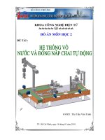
3.1.1 Block diagram of the system
Figure 3.1: System block diagram
Functions of blocks:
+ Power block: provides power to the system.
+ Button block: controls the system.
+ Sensor block: identifies bottle positions and counts products.
+ Conveyor belt block: moves bottles in and out.
14
+ Water filling block: supplies water to the bottles.
+ Bottle cap supply block: supply caps to the bottles.
+ Bottle cap screw block: seals the bottle.
+ Rotary block: holds and moves bottles at a 90-degree angle.
+ Central processing block: receives, processes information, and controls other blocks.
+ Interface screen block: Displays the system's operating process on the screen, we can
monitor and customize system parameters there.
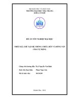
3.1.2 System procedures
+ Empty 330ml bottles are placed onto conveyor belt 1 to the water filling position.
+ After 2 seconds, the system pumps and fills the 330ml bottles within 6 seconds.
+ After completion, the system halts for 1 second before rotating the turntable to
prevent water spillage while in motion. Then, the turntable rotates the bottle to the
capping position.
+ At the capping position (capping process takes 3 seconds).
+ Bottles are then moved out onto the conveyor belt.
Figure 3.2: System process
Figure 3.3: Steps of the implementation process
15
* Water extraction process 7s
The tray rotates 90 degrees in 1 second
Take the 1s cap
Unscrew the cap for 2 s
Take out conveyor belt 1s
=> 1 hour is approximately 450 bottles
3.1.3 Select system equipment
3.1.3.1 PLC control block S7-1200
The group chose PLC S7-1200 1214C DC/DC/DC from Siemens. The group's
system has a total of 11 DI inputs and 8 DO outputs. While the S7-1200 1214C
DC/DC/DC has 14DI, the 10DO can be said to meet the group's requirements, and
with its compact design, easy-to-use Tia Protal programming software along with IO
expandability. , a SCADA design interface with a rich library, so this is the best
choice.
Figure 3.4: PLC S7-1200 1214C DC/DC/DC
Function
CPU 1214C DC/DC/DC
Locally integrated I/O:
Number type
14 inputs/10 outputs
Similar style
2 inputs/2 outputs
Work memory
100KB
Woad memory
4MB
Expansion of signal modules
8
Communication modules
3 (expand to the left)
High speed counters:
6
Single phase
3 at 100 kHz, 3 at 30 kHz
Square phase
3 at 80 kHz, 3 at 20 kHz
Pulse outputs
2
PROFINET
2 Ethernet transmission ports
Figure 3.5: Catalog S7-1200 1214C DC/DC/DC
16
3.1.3.2 Power block
+ Conveyor motor and capping motor utilize a 24VDC power supply with a current
draw of up to 2A.
+ Proximity sensors operate using a voltage range of 6-36VDC, with a maximum
current consumption of 300mA.
+ Optical sensors require a voltage range of 6-36VDC, with a maximum current draw
of 35mA.
PLC S7-1200 1214C DC/DC/DC operates using a 24VDC power supply with a
maximum current consumption of 1500mA.
+ The pneumatic control system and intermediate relays operate at a voltage of
24VDC.
=> Based on these technical specifications, the team decided to opt for a 24VDC – 5A
beehive power supply to power the entire system.
Figure 3.6: Honeycomb source
Input voltage
AC 220V
Output voltage
DC 24V 5A
Wattage
120
Size
199x98x38, 0,52Kgs
Figure 3.7: Technical specifications
*For our group's water pump motor, we use 12VDC, 3A power
17
Figure 3.8: 12VDC-3A Source
Input voltage
100V-240V
Output voltage
12V-3A
total length
1m5
Jack prohibits DC output
5.5 x 2.5mm (fits 5.5 x 2.1mm)
Figure 3.9: Technical specifications
3.1.3.3 Button block
Push button is used to close the electrical circuit in the low voltage circuit.
Normally open push button is used to control the system.
Figure 3.10: Push button
Plastic push button without light (Press release)
Number of contacts
1NO + 1NC
Number of operating voltages
AC/DC 230,380
Contact resistance
<50mΩ
Figure 3.11: Technical specifications
3.1.3.4 Relay switching device
Uses: The on/off contact consists of 3 contacts NC (normally closed), NO
(normally open) and COM (common pin) completely isolated from the main
circuit board. In the normal state, NC will be connected to COM when not
activated. COM activation state will change to NO connection and lose connection
with NC.
18
Figure 3.12: Relay in practice
Coli coil voltage
24VDC
Electric
5A
Number of contact pairs
4 pairs
Lights
Have
Figure 3.13: Technical specifications
3.1.3.5 Water filling block
The 12VDC pump motor is suitable for the production line's 297ml Nuti Food
milk bottle, with a flow rate of 5L/minute. It takes the motor 6 seconds to pump
297ml.
Figure 3.14: Pump motor
Voltage
12VDC
Pressure
0.6Mpa
High self-suction
1m5
High speed
20m
Automatic pressure switch off
Have
Flow
5L/Min
Weight
0,6Kg
Pipe in and out
10mm
Figure 3.14: Technical specifications
19