Báo cáo hóa học: " Paraunitary Oversampled Filter Bank Design for Channel Coding" docx
Bạn đang xem bản rút gọn của tài liệu. Xem và tải ngay bản đầy đủ của tài liệu tại đây (1.1 MB, 10 trang )
Hindawi Publishing Corporation
EURASIP Journal on Applied Signal Processing
Volume 2006, Article ID 31346, Pages 1–10
DOI 10.1155/ASP/2006/31346
Paraunitary Oversampled Filter Bank Design for
Channel Coding
Stephan Weiss,
1
Soydan Redif,
1
Tom Cooper,
2
Chunguang Liu,
1
Paul D . Baxter,
2
and John G. McWhirter
2
1
Communications Research Group, School of Electronics and Computer Science, University of Southampton,
Southampton SO17 1BJ, UK
2
Advanced Signal and Information Processing Group, QinetiQ Ltd, Malvern, Worcestershire WR14 3PS, UK
Received 20 September 2004; Revised 25 July 2005; Accepted 26 July 2005
Oversampled filter banks (OSFBs) have been considered for channel coding, since their redundancy can be utilised to permit
the detection and correction of channel errors. In this paper, we propose an OSFB-based channel coder for a correlated additive
Gaussian noise channel, of which the noise covariance matrix is assumed to be known. Based on a suitable factorisation of this
matrix, we develop a design for the decoder’s synthesis filter bank in order to minimise the noise power in the decoded signal,
subject to admitting perfect reconstruction through paraunitarity of the filter bank. We demonstrate that this approach can lead to
a significant reduction of the noise interference by exploiting both the correlation of the channel and the redundancy of the filter
banks. Simulation results providing some insight into these mechanisms are provided.
Copyright © 2006 Hindawi Publishing Corporation. All rights reserved.
1. INTRODUCTION
The redundancy and design freedom afforded by oversam-
pled filter banks (OSFBs) has in the past been exploited for
robustness towards quantisation of subband signals [1–3],
reconstruction of erased or erroneously received subband
samples [4, 5], or for the design of error correction coders
[6, 7]. More recently, in [8], a systematic parallelism between
block codes and oversampled filter bank systems for channel
coding has been drawn, whereby the system design is based
on unquantised “soft-input” signals [9].
The channel coding schemes in [2, 3, 6–9] are based on
an encoding stage using a preset analysis filter bank. The de-
sign freedom afforded in the decoding stage formed by the
oversampled synthesis filter bank is then utilised to find the
solution that reconstructs the signal—either perfectly or in
the mean-square error sense—while ideally projecting away
from the noise. The filter banks in [6–9]areconstructedfrom
FFTs, which leads to low-cost implementations, and have
been shown to be very robust towards burst-typ e errors, and
are easily compatible with OFDM-based modulation system.
If the additive channel noise is correlated, the projection
in [8] is performed in the direction of the principal compo-
nents of the noise subspace, which ideally is restricted such
that a noise-free signal subspace exists. Also, in [6–9], the
synthesis design is, despite some degrees of freedom (DOFs)
due to oversampling, limited by the a priori choice of the
analysis filter bank. In [10], the synthesis filter bank is given
more flexibility by the design aiming at the suppression of the
channel noise under the constraint of invertibility, such that
an analysis filter bank encoder can be derived from the syn-
thesis bank. However, the filter bank design in [10]isbased
on a crude iterative method that can prove the potential of
the approach but is otherwise far from being optimal.
Therefore, in this paper, we follow the channel coding
scheme in [10] for a correlated additive Gaussian noise chan-
nel, but apply a considerably improved constrained synthesis
filter bank design method based on the second-order sequen-
tial best rotation (SBR2) algorithm [11]. By linking the re-
maining noise variance a fter decoding to the covariance ma-
trix of the channel noise as a function of the synthesis filter
bank, a suitable broadband eigenvalue decomposition using
SBR2 leads to a paraunitary filter bank design that exploits
both the correlation of the channel noise as well as the DOFs
provided by the OSFBs.
The paper is organised as follows. Based on a brief de-
scription of filter banks in Section 2, the general channel
coding structure is presented. With the aim of minimising
the impact of additive channel noise on the decoded sig-
nal, we derive a noise power term, which can be utilised
as a cost function for the channel coder design. The pro-
posed constrained optimisation scheme for the synthesis fil-
ter bank is outlined in Section 3, which aims to minimise
the channel noise power at the decoder output subject to the
2 EURASIP Journal on Applied Signal Processing
X(z)
X(z)
H
0
(z)
N
Y
0
(z)
N
G
0
(z)
H
1
(z)
N
Y
1
(z)
N
G
1
(z)
H
K–1
(z)
N
Y
K–1
(z)
N
G
K–1
(z)
Analysis filter bank Synthesis filter bank
.
.
.
.
.
.
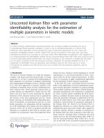
Figure 1: Subband decomposition of a signal X(z).
filter bank being paraunitar y, and therefore perfectly recon-
structing. Some insight into the functioning of the channel
coder design is provided by simulation in Section 4.Conclu-
sions are drawn in Section 5.
In terms of notation, vector quantities are denoted by ei-
ther lowercase boldface or underscored variables, such as v or
V
, w hile matrix quantities are boldface uppercase, such as R.
Indexed vectors or matrices refer to quantities with polyno-
mial entries, such as H(z). Finally, a transform pair, such as
the Fourier or z-transform, is denoted as h[n]
◦—• H(e
jΩ
)
or h[n]
◦—• H(z), respectively.
2. SYSTEM MODEL
Based on the description of basic filter bank structures in
Section 2.1 and their polyphase description in Section 2.2 ,a
model of the proposed encoder and decoder together with
the transmission model is discussed in Section 2.3.
2.1. Oversampled filter banks
Figure 1 shows a general filter bank structure comprising of
an analysis and a synthesis stage. The analysis filter bank
splits a full-band signal X(z) into K frequency bands by a
series of bandpass filters H
k
(z), k = 0, 1, , K − 1, and dec-
imates by a factor N
≤ K, resulting in so-called “subband”
signals Y
k
(z). The dual operation of reconstructing a full-
band signal from the K subband signals is accomplished by a
synthesis filter bank, where upsampling by N is followed by
interpolation filters G
k
(z), k = 0, 1, , K − 1.
The purpose of oversampling by a ratio K/N > 1 rather
than a critical decimation by K has application-specific rea-
sons, and has in the past, for example, enabled subband
adaptive filtering techniques for acoustic echo cancellation
[12], beamforming [13–15], or equalisation [16]bypermit-
ting independent processing of the subband signals. In these
cases, the filters have to be highly frequency selective, and the
redundancy introduced through oversampling is located in
the spectral overlap region of the filters within the filter bank
system.
The redundancy afforded by OSFBs has more recently
attracted attention for channel coding [6, 7]. There, a code
rate N/K < 1 can ensure robustness against noise interfer-
ence, w ith the aim of restoring noise-corrupted samples due
to the redundant format in which the data is transmitted.
The analysis and synthesis filter banks function as encoder
and decoder, while the filters H
k
(z)andG
k
(z) are no longer
limited to a bandpass design, but will rather be selected ac-
cording to the characteristics of the interfering noise.
2.2. Polyphase matrices
For implementation and analysis purposes, OSFBs as shown
in Figure 1 are conveniently represented by polyphase anal-
ysis and synthesis matrices. The former is based on a type-I
polyphase expansion of the analysis filters H
k
(z)[17]:
H
k
(z) =
N−1
n=0
z
−n
H
k,n
z
N
,(1)
with polyphase components H
k,n
(z), and a type-II decompo-
sition [17] of the input signal
X(z)
=
N−1
n=0
z
−N+n−1
X
n
z
N
,(2)
with polyphase components X
n
(z). This allows us to denote
the vector of subband signals Y
(z)as
⎡
⎢
⎢
⎣
Y
0
(z)
.
.
.
Y
K−1
(z)
⎤
⎥
⎥
⎦
Y(z)
=
⎡
⎢
⎢
⎣
H
0,0
(z) ··· H
0,N−1
(z)
.
.
.
.
.
.
.
.
.
H
K−1,0
(z) ··· H
K−1,N−1
(z)
⎤
⎥
⎥
⎦
H(z)
⎡
⎢
⎢
⎣
X
0
(z)
.
.
.
X
N−1
(z)
⎤
⎥
⎥
⎦
X(z)
.
(3)
Therefore, the filter bank can be represented by a demul-
tiplexing of the input signal into N lines, followed by a
multiple-input multiple-output (MIMO) system described
by the polyphase analysis matrix H(z). This structure is seen
as part of Figure 2.
Analogously, a polyphase synthesis matrix G(z)
∈
C
N×K
(z) can be defined based on a polyphase expansion
of G
k
(z), yielding the synthesis filter bank representation in
Figure 2 comprising G(z) followed by an N-fold multiplexer.
A filter bank system is perfectly reconstructing if
G(z)H(z)
= z
−Δ
I
N
. (4)
The design of such a system can be demanding in terms
of the number of coefficients that need to be optimised. A
reduction of the parameter space by, for example, deriving
all K filters from a prototype by modulation [2, 18]orby
permitting only symmetric filter impulse responses [4, 18]
often makes the problem tractable.
Stephan Weiss et al. 3
W
0
(z) W
1
(z) W
K−1
(z)
X(z) X
0
(z) Y
0
(z)
Y
0
(z)
X
0
(z)
X
1
(z) Y
1
(z)
Y
1
(z)
X
1
(z)
N
N
N
X
N−1
(z) Y
K−1
(z)
Y
K−1
(z)
X
N−1
(z)
X(z)
N
N
N
H(z) G(z)
···
.
.
.
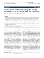
Figure 2: General setup of a channel coder based on K channel analyses and synthesis filter banks, arranged around the transmission over
K additive Gaussian noise channels.
2.3. Setup and channel coder
The overall model of the considered system is provided in
Figure 2. In the transmitter, the N polyphase components
of X(z) are encoded by the polyphase analysis matrix H(z).
The transmission could either employ K separate channels
as shown in Figure 2, or multiplex the K encoder outputs
onto a single signal transmitted over a single-input single-
output channel. This channel is subject to corruption by ad-
ditive Gaussian wide-sense-stationary (WSS) noise, and for
simplicity is assumed to be nondisp ersive.
In the case of a dispersive channel, the model in Figure 2
can also be applied, if an ideal zero-forcing (ZF) equaliser
is employed prior to decoding by the polyphase synthesis
matrix G(z). While the channel and the ZF equaliser an-
nihilate each other for the signal path, in the noise path,
the ZF equaliser can be absor bed into the innovations fil-
ter model producing the additive noise components W
k
(z),
k
= 0, 1, , K − 1. This absorption would result in an addi-
tional shaping of the channel noise corrupting the K received
signals
Y
k
(z), and provide an additional incentive for chan-
nel coding that can exploit the spatiotemporal structure of
the noise.
In the receiver after decoding, the polyphase components
X
n
(z) can be collected similar to X(z)in(3)inavector
X(z),
which is g iven by
X(z) = G(z)
Y(z)+W(z)
,(5)
whereby Y
(z) = H(z)X(z) ∈ C
K
(z)andW(z) ∈ C
K
(z)con-
tain the subband signal components of the transmitted data
and the noise, respectively. Selecting perfect reconstruction
filter banks G(z)H(z)
= I
N
,
E
(z) = X(z) −
X(z) =−G(z)W(z)(6)
is obtained.
In order to assess the total received noise variance σ
2
e
in
X(z), let the N-element vector e[m] contain the N time series
associated with the z-domain quantities in E
(z) •—◦ e[m],
which depend on the time index m in the decimated domain.
Thus, we have
σ
2
e
=
1
N
tr
E
e[m]e
H
[m]
,(7)
where tr
{·} denotes trace and E {·} is the expec tation opera-
tor. Defining the autocorrelation matrix
R
ee
[τ] = E
e[m]e
H
[m − τ]
(8)
and its z-transform R
ee
(z) •—◦ R
ee
[τ] denoting the power
spectrum of the process e[m][17], the noise variance is given
by
σ
2
e
=
1
N
tr
R
ee
[0]
=
1
N
tr
R
ee
(z)
z=0
(9)
=
1
N
tr
G(z)R
ww
(z)
G(z)
z=0
. (10)
The notation in (10 ) uses the para-Hermitian operator
{·}
,
which applies a complex conjugate transposition and a time
reversal [17] to its operand. Note that (6)hasbeenex-
ploited to trace the noise variance back to the power spec-
trum R
ww
(z), which is the z-transform of the covariance ma-
trix of the channel noise,
R
ww
[τ] = E
w[m]w
H
[m − τ]
, (11)
with w[m]
◦—• W(z)asdefinedinFigure 2 .
3. CHANNEL CODER AND FILTER BANK DESIGN
Based on the idea of the channel coder outlined in Section
3.1, this section considers a suitable factorisation of the
power spectrum at the decoder output in Section 3.2,ad-
mitting a useful coder design in Section 3.3 . An algorithm
to construct filter banks achieving this design is reviewed in
Section 3.4.
3.1. Proposed coding approach
It is the quantity σ
2
e
in (7) which is generally minimised in
some sense in channel coding. In [8], for a given H(z), the de-
grees of freedom (DOFs) in the design of G(z)areexploited
to minimise σ
2
e
in the MSE sense. Note however that this ap-
proach limits the DOFs that can be dedicated to fit the syn-
thesis matrix to the spatiotemporal structure of the noise.
Therefore, we proposed to minimise (7) by optimising
G(z) without restriction by a specific H(z). The only condi-
tion placed on G(z) is that it admits a right inverse G
†
(z)
such that G(z)G
†
(z) = z
−Δ
. A stronger restrict ion than sim-
ple invertibility placed on G(z) is paraunitarity, which how-
ever has two important advantages: (i) the analysis filter bank
is immediately given by H(z)
=
G(z), and (ii) paraunitar ity
provides a minimum-norm solution such that the transmit
power is limited. As a counterexample, an invertible G(z)
might elicit an ill-conditioned H(z) which may attempt to
4 EURASIP Journal on Applied Signal Processing
transmit highly powered signals over subspaces associated
with near-rank deficiency.
3.2. Factorisation of the noise covariance matrix
We approach the minimisation of (10) via a factorisation of
the power spectrum
R
ww
(z) = U(z)Γ(z)
U(z) (12)
such that U(z)
∈ C
K×K
(z) is paraunitary and st rongly decor-
relates R
ww
(z), that is,
Γ(z)
= diag
Γ
0
(z), Γ
1
(z), , Γ
K−1
(z)
(13)
is a diagonal matrix with polynomial entries Γ
k
(z). This fac-
torisation presents a broadband eigenvalue decomposition,
which can be further specified by demanding Γ(z)tobespec-
trally majorised [11, 19] such that the power spec tral den-
sity (PSD) of the kth noise component Γ
k
(e
jΩ
) = Γ
k
(z)
z=e
jΩ
evaluated on the unit circle obeys
Γ
k
e
jΩ
≥
Γ
k+1
e
jΩ
∀
Ω, k = 0, 1, , K − 2, (14)
similar to the ordering of the singular values in a singu-
lar value decomposition. Note that par aunitarity or loss-
lessness of U(z) conserves power, that is, tr
{Γ(z)}|
z=0
=
tr{R
ww
(z)}|
z=0
.
3.3. Channel coding design
Using the redundancy N<Kdue to oversampling, we can
construct G(z)fromU(z) to select the lower (and therefore
smallest) N elements on the main diagonal of Γ(z). Let
U(z)
=
U
0
(z) U
1
(z) ··· U
K−1
(z)
, (15)
then
G(z)
=
⎡
⎢
⎢
⎢
⎢
⎢
⎣
U
K−N
(z)
U
K−N+1
(z)
.
.
.
U
K−1
(z)
⎤
⎥
⎥
⎥
⎥
⎥
⎦
∈ C
N×K
(z), (16)
such that G(z)U(z)
= [0
N×K−N
I
N
]. If
Γ(z)
=
Γ
00
(z) Γ
01
(z)
Γ
10
(z) Γ
11
(z)
(17)
with Γ
11
(z) ∈ C
N×N
and the remaining submatrices of ap-
propriate dimension, then the noise power at the decoder
output becomes
σ
2
e
=
1
N
tr
Γ
11
(z)
z=0
=
1
N
K−1
i=K−N
2π
0
Γ
i
e
jΩ
dΩ.
(18)
Therefore, the spectral majorisation in the broadband eigen-
value decomposition (12) is essential to the success of the
proposed channel coder design.
3.4. Sequential best rotation algorithm
In order to achieve the factorisation in (12) fulfilling spec-
tral majorisation according to (14), we use the second-order
sequential best rotation (SBR2) algorithm [11]. In the fol-
lowing, only a brief description of the algorithm is provided,
while for an in-depth treatment, the reader is referred to
[11, 20].
SBR2 is an iterative broadband eigenvalue decomposition
technique based on second-order statistics only and can be
seen as a generalisation of the Jacobi algorithm. The decom-
position after L iterations is based on a paraunitary matrix
U
L
(z) =
L
i=0
Q
i
Λ
i
(z), (19)
whereby Q
i
is a Givens rotation and the matrix Λ
i
(z)isapa-
raunitary matrix of the form
Λ
i
(z) = I − v
i
v
H
i
+ z
−Δ
i
v
i
v
H
i
, (20)
with v
i
= [
0
··· 010··· 0
]
H
containing zeros except
for a unit element in the δ
i
th position. Thus, Λ
i
(z)isaniden-
tity mat rix with the δ
i
th diagonal element replaced by a delay
z
−Δ
i
.
At the ith step, SBR2 will eliminate the largest off-
diagonal element of the matrix U
i−1
(z)R
ww
(z)
U
i−1
(z), which
is defined by the two corresponding subchannels and by a
specific lag index. By delaying the two contributing subchan-
nels appropriately with respect to each other by selecting the
position δ
i
and the delay Δ
i
, the lag value is compensated.
Thereafter, a Givens rotation Q
i
can eliminate the targeted
element such that the resulting two terms on the main diag-
onal are ordered in size, leading to a diagonalisation and at
the same time accomplishing a spectral majorisation.
Hence, each step comprises of optimising the parame-
ter set
{δ
i
, Δ
i
, θ
i
}. While the largest off-diagonal e lement in
U
i−1
(z)R
ww
(z)
U
i−1
(z) is eliminated, the remainder of the
matrix is also a ffected. In extensive simulations, SBR2 has
proven very robust and stable in achieving both a diagonali-
sation and spectral majorisation of any given covariance ma-
trix, whereby the algor ithm is stopped either after reaching
a certain measure for suppressing off-diagonal terms or after
exceeding a defined number of iterations [11, 20]. The order
O
OSFB
of the filter bank defined by the paraunitar y poly phase
matrix U
L
(z)isboundedbyO
OSFB
≤
L
i=0
Δ
i
. Since the in-
dividual delays Δ
i
are optimised by the algorithm and not
known a priori, the filter bank order O
OSFB
cannot be de-
termined or limited a priori to applying SBR2 to the power
spectral matrix R
ww
(z).
4. SIMULATIONS AND RESULTS
To illustrate the proposed channel coding design, three
design examples are demonstrated in the following. The
first design assumes an independent transmission across
K subchannels, while the latter two are based on a time-
multiplexed transmission leading to correlation between the
K virtual subchannels.
Stephan Weiss et al. 5
4.1. Multichannel transmission
We assume the transmission scenario shown in Figure 2,
whereby K subchannels are available and are corrupted by
Gaussian noise processes w
k
[m], k = 0, 1, , K − 1, such
that
E
w
k
[m]w
j
[m − τ]
=
⎧
⎨
⎩
0fork = j,
r
k
[τ] ◦—• R
k
e
jΩ
for k = j.
(21)
Specifically, for the example below, we assume that K
= 6
and that the w
k
[m] are produced by uncorrelated unit vari-
ance and zero-mean Gaussian processes by passing through
innovation filters p
k
[m] ◦—• P
k
(z)[21],
⎡
⎢
⎢
⎢
⎢
⎣
P
0
(z)
P
1
(z)
P
2
(z)
P
3
(z)
⎤
⎥
⎥
⎥
⎥
⎦
=
⎡
⎢
⎢
⎢
⎢
⎣
11 1 1
1
−11−1
11
−1 −1
1
−1 −11
⎤
⎥
⎥
⎥
⎥
⎦
·
⎡
⎢
⎢
⎢
⎢
⎣
1
z
−1
z
−2
z
−3
⎤
⎥
⎥
⎥
⎥
⎦
,
P
4
(z) = P
5
(z) = 10,
(22)
such that r
k
[τ] =
m
p
k
[m] p
∗
k
[m − τ]. The resulting power
spectrum R
ww
(z) is a diagonal matrix with P SDs R
k
(e
jΩ
)as
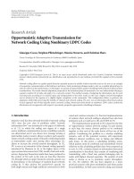
defined in (21) and shown in Figure 3(a) on its diagonal.
Prior to running the SBR2 algorithm on R
ww
(z), its
purely diagonal str ucture must be perturbed through the ap-
plication of an arbitrary paraunitary matrix. Thereafter, in-
dependent of this perturbation, SBR2 achieves a diagonal-
isation of Γ( z)afterL
≈ 250 iterations, whereby a ratio
of approximately 10
−3
between the energy of off-diagonal
and on-diagonal terms is reached. However, recall from (17)-
(18) that the minimisation of the noise power σ
2
e
at the de-
coder output does not necessitate the diagonality of Γ(z)but
does strongly depend on its spectral majorisation. To exam-
ine the latter after convergence of SBR2, the PSDs of the
main diagonal elements Γ
k
(e
jΩ
) are depicted in Figure 3(b).
Quite clearly, except for a low-power region of the bands
Γ
4
(e
jΩ
)andΓ
5
(e
jΩ
)nearΩ = π, spectral majorisation has
been achieved in the sense of (14). Interestingly, the gen-
eral shape of the PSDs in Figure 3(b) closely follows those in
Figure 3(a), but frequency intervals have been reassigned to
different subchannels and have been ordered in descending
power.
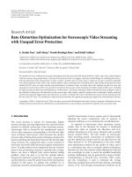
Integrating over the PSDs in Figure 3 provides the noise
variance of the various subchannels, which are illustrated
in Figure 4 for R
ww
(z)andΓ(z) without and with coding,
respectively. The coder would then utilise those N coded
subchannels represented in Γ(z) that carry the lowest noise
power. These N coded subchannels convey the N polyphase
components of the transmitted signal X(z), which accord-
ing to Figure 4 are subject to different levels of noise. Note
that the polyphase component transmitted over the lowest
subchannel provides the best protection against noise, while
noise introduced on higher subchannels increases in power.
This fact can be exploited for unequal error protection to, for
example, high-quality high-speed video transmission.
In order to demonstrate how the residual noise power in
the decoded subchannels depends on the order of the filter
−15
−10
−5
0
5
10
15
20
25
Noise PSD (dB)
0
0.05 0.10.15 0.20.25 0.30.35 0.40.45 0.5
Normalised angular frequency Ω/2π
R
0
(e
jΩ
)
R
1
(e
jΩ
)
R
2
(e
jΩ
)
R
3
(e
jΩ
)
R
4
(e
jΩ
)
R
5
(e
jΩ
)
(a)
−15
−10
−5
0
5
10
15
20
25
Noise PSD (dB)
0
0.05 0.10.15 0.20.25 0.30.35 0.40.45 0.5
Normalised angular frequency Ω/2π
Γ
0
(e
jΩ
)
Γ
1
(e
jΩ
)
Γ
2
(e
jΩ
)
Γ
3
(e
jΩ
)
Γ
4
(e
jΩ
)
Γ
5
(e
jΩ
)
(b)
Figure 3: PSDs on the main diagonals of (a) the power spectrum
R
ww
(z) of the channel noise consisting of the R
k
(e
jΩ
)of(21)and
(b) Γ(z) after application of the SBR2 algorithm.
bank, Figure 5(a) provides an evolution of the total received
noise power in dependence on the number of iterations used
for SBR2 and on the number of selected subchannels N.If
all subchannels are selected, that is, N
= K = 6, no re-
dundancy can be exploited and the total noise power cannot
be reduced. For N<4, the channel characteristics permit
the exploitation of low-noise subspaces, which is achieved
through spectral majorisation of the power spec trum due to
the filter banks. Note that in Figure 5, initially a small degra-
dation of the cumulative noise powers for N<6withrespect
to (21) occurs as a result of the random perturbance of the
diagonal R
ww
(z) by an arbitrary paraunitary matrix. It is ev-
ident from Figure 5 that the required filter order, and there-
fore the complexity of the resulting filter bank, depends on
the code rate, that is, the lower N and hence the higher the
oversampling ratio, the more iterations are required to fully
exploit the available potential in reducing the output noise
power σ
2
e
=
K−1
k=K−N
γ
k
[0]. The order of the polynomial ma-
trix U
L
(z), and therefore the filter bank matrices H(z)and
G(z)afterL iterations, is given in Figure 5(b), whereby tails
of the filters can be truncated if a lower numerical resolution
is sufficient. In the case of channel coding, infinite numerical
precision would be wasteful, while quantisation noise is ac-
ceptable if its power is well below the level of residual channel
noise in Figure 5(a).
6 EURASIP Journal on Applied Signal Processing
0
10
20
10 log
10
r
k
[0] (dB)
012345
Index k
(a)
0
10
20
10 log
10
γ
k
[0] (dB)
012345
Index k
(b)
Figure 4: Variances of (a) uncoded noise r
k
[0] and (b) coded subchannels γ
k
[0] = (1/2π)
2π
0
Γ
k
(e
jΩ
)dΩ.
−5
0
5
10
15
20
25
10 log
10
K−1
k
=K−N
γ
k
[0] (dB)
0
50 100 150 200 250 300 350 400
Iterations L
N
= 6
N
= 5
N
= 4
N
= 3
N
= 2
N
= 1
(a)
0
100
200
300
400
Filter bank order
0
50 100 150 200 250 300 350 400
Iterations L
Floating point
16 bits quantised
12 bits quantised
8 bits quantised
4 bits quantised
(b)
Figure 5: (a) cumulative variance of N subchannels containing the
lowest noise power after L iterations of SBR2 and (b) filter bank or-
der after L iterations; the curves are averaged over 50 random trials
with different paraunitary matrices perturbing the originally diag-
onal R
ww
(z); γ
k
[0] is defined in Figure 4.
If a decimation factor of N = 2 is chosen for the fil-
ter banks, only the two coded subchannels with the lowest
noise variance in Figure 4(b) will be utilised. The reduction
in noise power results in an SNR enhancement of the coded
scheme with respect to a transmission scenario of identical
symbol throughput based on maximum-ratio combining of
the K
= 6 channels in Figure 4(a) of 7.5 dB. Note that a
maximum-ratio combiner uses a zero-order diagonal G(z),
and accor dingly H(z) with the elements inversely propor-
tional to the standard deviation of the noise in the subchan-
nels.
Some insight into how the reduction of noise power is
gained by the proposed coding method for the case N
= 2
is demonstrated in Figure 6, where the resulting characteris-
tics of a K
= 6 channel filter banks decimated by N = 2are
shown. The displayed characteristics refer to the filter bank
structure given in Figure 1, and are plotted against the PSDs
of the channel noise after N
= 2-fold expansion. Figure 6
very clearly underlines the functioning of the coder, which
effectively excludes the two subchannels with high noise
power from transmission, while in all other subchannels, the
transmitted power is concentrated in frequency bands where
the noise PSD assumes its lowest values.
4.2. Time-multiplexed transmission
In the following, we consider the case where the noise in the
K subchannels in Figure 2 may be mutually correlated. This
can occur through a time-multiplexed transmission of the K
encoded symbols over the same channel corrupted by noise
w[m], which is assumed to be modelled as a unit-variance
zero-mean Gaussian WSS process undergoing an innovation
filter p[m]. Therefore, the autocorrelation function of w[m]
is given by r[τ]
=
m
p[m]p
∗
[m − τ] ◦—• R(z). After de-
multiplexing into K channels in the receiver, the resulting
noise power spectrum R
ww
(z) can be shown to be given by
the pseudocirculant matrix
R
ww
(z) =
⎡
⎢
⎢
⎢
⎢
⎢
⎣
R
0
(z) R
1
(z) ··· R
K−1
(z)
z
−1
R
K−1
(z) R
0
(z) R
K−2
(z)
.
.
.
.
.
.
.
.
.
.
.
.
z
−1
R
1
(z) ··· z
−1
R
K−1
(z) R
0
(z)
⎤
⎥
⎥
⎥
⎥
⎥
⎦
(23)
containing the K poly phase components R
k
(z), k = 0, 1, ,
K
− 1, of R(z),
R(z)
=
K−1
k=0
R
k
z
K
z
−k
. (24)
Stephan Weiss et al. 7
−40
−20
0
|G
k
(e
jΩ
)|
2
,
R
k
(e
jΩ
)/10 (dB)
00.10.20.30.40.50.60.70.80.91
Normalised angular frequency Ω/2π
−40
−20
0
|G
k
(e
jΩ
)|
2
,
R
k
(e
jΩ
)/10 (dB)
00.10.20.30.40.50.60.70.80.91
Normalised angular frequency Ω/2π
−40
−20
0
|G
k
(e
jΩ
)|
2
,
R
k
(e
jΩ
)/10 (dB)
00.10.20.30.40.50.60.70.80.91
Normalised angular frequency Ω/2π
−40
−20
0
|G
k
(e
jΩ
)|
2
,
R
k
(e
jΩ
)/10 (dB)
00.10.20.30.40.50.60.70.80.91
Normalised angular frequency Ω/2π
−100
−50
0
|G
k
(e
jΩ
)|
2
,
R
k
(e
jΩ
)/10 (dB)
00.10.20.30.40.50.60.70.80.91
Normalised angular frequency Ω/2π
−100
−50
0
|G
k
(e
jΩ
)|
2
,
R
k
(e
jΩ
)/10 (dB)
00.10.20.30.40.50.60.70.80.91
Normalised angular frequency Ω/2π
Figure 6: PSDs of channel noise processes w
k
[m], k = 0, 1, , K − 1, decimated by N = 2 (dashed) and magnitude responses of the filters
|G
k
(e
jΩ
)|=|H
k
(e
jΩ
)| (solid).
−30
−20
−10
0
10
S
ww
(e
jΩ
)(dB)
00.05 0.10.15 0.20.25 0.30.35 0.40.45 0.5
Normalised angular frequency Ω/2π
Figure 7: Channel noise PSD in time multiplex Channel II.
Channel I
In a first case, the multiplex channel is assumed to be cor-
rupted by an interfering radio signal occupying a quarter
of the available bandwidth. The interference is modelled by
a zero-mean unit-variance white Gaussian noise exciting a
49th-order bandpass FIR filter, which results in the channel
noise PSD shown in Figure 7. The PSD within each of the
subchannels described by R
ww
(z)foranygivenK is identical.
Here, different from Section 4.1, the coder has to addition-
ally exploit the correlation between the K subchannels. Af-
ter application of the SBR2 algorithm, the reduction in noise
power—the ratio between the output power of the coder to
10
−2
10
−1
10
0
σ
2
e
/σ
2
w
00.10.20.30.40.50.60.70.80.91
Code rate N/K
K
= 2
K
= 3
K
= 4
K
= 5
K
= 6
K
= 8
K
= 10
K
= 12
K
= 15
K
= 20
Max. ratio
Figure 8: Noise reduction achieved by the proposed coding scheme
over Channel II characterised in Figure 7.
the power of the channel noise process w[m]—for various
choices of K and N is depicted in Figure 8.Incomparisonto
8 EURASIP Journal on Applied Signal Processing
0
0.2
0.4
0.6
0.8
1
2π
0
Γ
i
(e
jΩ
)dΩ
02468101214161820
Channel index i
Figure 9: Spectral majorisation in the decomposition of the noise
power spectral matrix R(z)bySBR2forK
= 20 channels.
maximum-ratio combining with identical symbol through-
put, the proposed coder in general performs consistently and
considerably better, whereby an increase in K permits both
a finer resolution to exploit spatial correlation as well as the
use of more flexible code rates N/K.
The proposed channel coder can exploit the spectral
characteristics of the channel noise well, and, provided a
sufficient resolution of the code rate, exhibits an approx-
imately constant output noise power once the code rate
reaches the approximately interference-free relative band-
width of 75% available over the channel.
Channel II
We select a power-line communication channel (PLC),
whose PSD in a worst-case scenario can be modelled as [22]
S
log
( f ) = 38.75| f |
−.72
dBm/Hz. (25)
Sampled at 30 MHz, an iterative least-squares fit has been
employed to derive an FIR innovation filter with 256
coefficients to produce the PSD characterised in (25)[23].
Applying SBR2 to the resulting noise power spectrum R (z),
an example for the resulting spectral majorisation is given
in Figure 9 for a decomposition into K
= 20 channels, for
which SBR2 yields a 37th-order filter bank matrix H(z). The
latter is reached with a stopping criterion of 10
3
for the ra-
tio between the total power and the power contained in off-
diagonal elements in U
L
(z)R
ww
(z)
U
L
(z). For this broadband
eigenvalue decomposition, a single strong eigenmode of the
noise is clearly visible. Therefore, if oversampling is applied
and the strongest eigenmodes of the noise subspace can be
deselected form transmission, the noise power in the de-
coded signal in the receiver can be significantly reduced. The
coding gain for the PLC simulation model in (25)isgivenin
Figure 10 for various selections of channels K,andcompared
to maximum-ratio combining by repeated transmission of
symbols over an otherwise uncoded channel.
Figure 10 suggests that the OSFB approach can provide
considerable coding gain at a high code rate close to unity
for the case of highly correlated noise. In order to exploit this,
K has to be chosen sufficientlylargeinordertooffer a high
resolution with respect to possible code rates.
In the following, we consider transmitting quadrature
amplitude modulated (QAM) symbols over the OSFB-coded
10
−1
10
0
σ
2
e
/σ
2
w
00.10.20.30.40.50.60.70.80.91
Code rate N/K
K
= 2
K
= 3
K
= 4
K
= 5
K
= 6
K
= 8
K
= 10
K
= 12
K
= 15
K
= 20
Max. ratio comb.
Figure 10: Coding gain of the OSFB coder applied to the PLC chan-
nel defined in (25)forvariousvaluesofK and different code rates.
10
−4
10
−3
10
−2
10
−1
BER
0.10.20.30.40.50.60.70.80.91
Code rate
16-QAM, BCH
16-QAM, OSFB
4-QAM, BCH
4-QAM, OSFB
Figure 11: BER for coding using M-QAM and OSFB and BCH
channel coding, in dependency on the code rate.
PLC channel. For a channel SNR of 3 dB, Figure 11 presents
results for different code rates for a QPSK/4-QAM and a 16-
QAM-based transmission.
As a comparison, we also present results for a (63, N
BCH
)
BCH-coded PLC channel, where N
BCH
is varied to achieve
variouscoderates[23]. The BCH-encoded bit stream is M-
QAM mapped and transmitted over the PLC channel. In the
receiver, after slicing and demapping, a BCH decoder aims to
recover the original bit stream. A (37,20) matrix interleaver,
imposing the same processing delay as the OSFB coder, is set
to assist in breaking up noise correlation and burst-type er-
rors. Although its computational complexity is hig her than
the various BCH coders, it is clear that the OSFB coder pro-
vides superior protection against correlated channel noise,
Stephan Weiss et al. 9
and almost enables the use of 16-QAM rather than QPSK
as opposed to a BCH coder, thus nearly doubling the data
throughput without sacrificing error protection.
5. CONCLUSIONS
In this paper, we have proposed a channel coding approach
based on OSFBs by first designing a decoder that minimises
the influence of correlated channel noise in the receiver, and
thereafter obtaining the encoder. By demanding paraunitar-
ity for the decoding OSFB, the latter step is trivial and ensures
a strict bound on the transmitted power. An OSFB design
method has been proposed, which is based on a broadband
eigenvalue decomposition and demonstrates good perfor-
mance in suppressing the correlated channel noise. Some in-
sight into the effects of the design have been given by consid-
ering transmission scenarios over K independent channels
or by time-multiplexed transmission, where the exploitation
of spatial or spectral correlations can bring substantial bene-
fits over a transmission of identical symbol throughput using
maximum-ratio combining of the subchannels.
The SNR enhancement gained from the proposed coding
architecture can be utilised in conjunction with the trans-
mission of quantised data such as found in binary-phase
shift keying or multilevel QAM symbols, such that the oc-
currence of symbol or bit errors is reduced. This has been
demonstrated by considering a power-line communications
scenario, whereby the proposed OSFB design can signifi-
cantly outperform standard channel coding techniques such
as BCH, offering a higher data throughput at identical pro-
tection against errors.
6. ACKNOWLEDGMENT
We would like to gratefully acknowledge the anonymous re-
viewers for insightful questions and helpful guidance.
REFERENCES
[1] Z. Cvetkovi
´
c and M. Vetterli, “Overcomplete expansions and
robustness,” in Proceedings of IEEE-SP International Sympo-
sium on Time-Frequency and Time-Scale Analysis (TFTS ’96),
pp. 325–328, Paris, France, June 1996.
[2] H. B
¨
olcskei and F. Hlawatsch, “Oversampled filter banks: opti-
mal noise shaping, design freedom, and noise analysis,” in Pro-
ceedings of IEEE International Conference on Acoustics, Speech,
and Signal Processing (ICASSP ’97), vol. 3, pp. 2453–2456, Mu-
nich, Germany, April 1997.
[3] H. B
¨
olcskei and F. Hlawatsch, “Noise reduction in oversam-
pled filter banks using predictive quantization,” IEEE Transac-
tions on Information Theory, vol. 47, no. 1, pp. 155–172, 2001.
[4] F. Labeau, L. Vandendorpe, and B. Macq, “Structures, factor-
izations, and design criteria for oversampled paraunitary fil-
terbanks yielding linear-phase filters,” IEEE Transactions on
Signal Processing, vol. 48, no. 11, pp. 3062–3071, 2000.
[5] T. Tanaka and Y. Yamashita, “On perfect reconstruction with
lost channel data in lapped pseudo-orthogonal transform,” in
Proceedings of 12th European Signal Processing Conference (EU-
SIPCO ’04), vol. 1, pp. 877–880, Vienna, Austria, September
2004.
[6] F. Labeau, L. Vandendorpe, and B. Macq, “Oversampled filter
banks as error correcting codes,” in Proceedings of 5th Interna-
tional Symposium on Wireless Personal Multimedia Communi-
cations (WPMC ’02), vol. 3, pp. 1265–1269, Honolulu, Hawaii,
USA, October 2002.
[7] F. Labeau, “Design and implementation issues in oversam-
pled filter banks,” in Proceedings of 36th Asilomar Conference
on Signals, Systems, and Computers, vol. 1, pp. 328–332, Pacific
Grove, Calif, USA, November 2002.
[8] F. Labeau, J. C. Chiang, M. Kieffer, P. Duhamel, L. Vanden-
dorpe, and B. Macq, “Oversampled filter banks as error cor-
recting codes: theory and impulse noise correction,” IEEE
Transactions on Signal Processing, vol. 53, no. 12, pp. 4619–
4630, 2005.
[9]J.KliewerandA.Mertins,“Error-resilienttransmissionof
waveform signals using overcomplete expansions and soft-
input source decoding,” in Proceedings of 12th European Sig-
nal Processing Conference (EUSIPCO ’04), vol. 1, pp. 879–882,
Vienna, Austria, September 2004.
[10] S. Weiss, “On the design of oversampled filter banks for chan-
nel coding,” in Proceedings of 12th European Signal Processing
Conference (EUSIPCO ’04), vol. 1, pp. 885–888, Vienna, Aus-
tria, September 2004.
[11] J. G. McWhirter and P. D. Baxter, “A novel technique for
broadband singular value decomposition,” in Proceedings of
12th Annual Workshop on Adaptive Sensor Array Processing
(ASAP ’04), MIT Lincoln Laboratory, Lexington, Mass, USA,
March 2004.
[12] W. Kellermann, “Analysis and design of multirate systems for
cancellation of acoustical echoes,” in Proceedings of IEEE Inter-
national Conference on Acoustics, Speech, and Signal Processing
(ICASSP ’88), vol. 5, pp. 2570–2573, New York, NY, USA, April
1988.
[13] F. Lorenzelli, A. Wang, D. Korompis, R. Hudson, and K. Yao,
“Subband processing for broadband microphone ar rays,” The
Journal of VLSI Signal Processing—Systems for Signal, Image,
and Video Technology, vol. 14, no. 1, pp. 43–55, 1996.
[14] S. Weiss, R. W. Stewart, M. Schabert, I. K. Proudler, and M.
W. Hoffman, “An efficient scheme for broadband adaptive
beamforming,” in Proceedings of 33rd Asilomar Conference on
Signals, Systems, and Computers, vol. 1, pp. 496–500, Pacific
Grove, Calif, USA, October 1999.
[15] W. H. Neo and B. Farhang-Boroujeny, “Robust microphone
arrays using subband adaptive filters,” IEE Proceedings—
Vision, Image and Signal Processing, vol. 149, no. 1, pp. 17–25,
2002.
[16] S. Weiss, S. R. Dooley, R. W. Stewart, and A. K. Nandi, “Adap-
tive equalisation in oversampled subbands,” IEE Electronics
Letters, vol. 34, no. 15, pp. 1452–1453, 1998.
[17] P. P. Vaidyanathan, Multirate Systems and Filter Banks,
Prentice-Hall, Englewood Cliffs, NJ, USA, 1993.
[18] M. Harteneck, S. Weiss, and R. W. Stewart, “Design of near
perfect reconstruction oversampled filter banks for subband
adaptive filters,” IEEE Transactions on Circuits and Systems—
Part II: Analog and Digital Signal Processing,vol.46,no.8,pp.
1081–1085, 1999.
[19] P. P. Vaidyanathan, “Theory of optimal orthonormal subband
coders,” IEEE Transactions on Signal Processing, vol. 46, no. 6,
pp. 1528–1543, 1998.
[20] S. Redif and T. Cooper, “Paraunitary filter bank design via a
polynomial singular-value decomposition,” in Proceedings of
IEEE International Conference on Acoustics, Speech, and Signal
Processing (ICASSP ’05), vol. 4, pp. 613–616, Philadelphia, Pa,
USA, March 2005.
10 EURASIP Journal on Applied Signal Processing
[21] A. Papoulis, Probability, Random Variables, and Stochastic Pro-
cesses, McGraw-Hill, New York, NY, USA, 3rd edition, 1991.
[22] T. Esmailian, F. R. Kschischang, and P. G. Gulak, “In-building
power lines as high-speed communication channels: channel
characterization and a test channel ensemble,” International
Journal of Communication Systems, vol. 16, no. 5, pp. 381–400,
2003.
[23] C. Liu, S. Weiss, S. Redif, T. Cooper, L. Lampe, and J. G.
McWhirter, “Channel coding for power line communication
based on oversampled filter banks,” in Proceedings of 9th In-
ternat ional Symposium on Power-Line Communications and
Its Applications (ISPLC ’05), pp. 246–249, Vancouver, British
Columbia, Canada, April 2005.
Stephan Weiss received the Dipl Ing. de-
gree from the University of Erlangen-
N
¨
urnberg, Erlangen, Germany, in 1995, and
the Ph.D. degree from the University of
Strathclyde, Glasgow, Scotland, in 1998,
both in electronic and electrical engineer-
ing. In 1999, he joined the Communications
Research Group within the School of Elec-
tronics and Computer Science at the Uni-
versity of Southampton, where he is a Se-
nior Lecturer. Prior to this appointment, he held a Visiting Lecture-
ship at the University of Strathclyde. In 1996/1997, he was a Visit-
ing Scholar at the University of Southern California. His research
interests are mainly in adaptive and ar ray signal processing, multi-
rate systems, and signal expansions, with applications in commu-
nications, audio, and biomedical signal processing. For his work in
biomedical signal processing, he was a corecipient of the 2001 Re-
search Award of the German society on hearing aids. He is a Mem-
ber of the VDE and EURASIP, a Senior Member of the IEEE, and a
Member of the IEE Signal Processing Professional Network Execu-
tive Team.
Soydan Redif received a B.Eng. (honours)
degree in electronic engineering from Mid-
dlesex University, London, in 1998. From
1999 to 2000, he was with the Communi-
cations Department at the Defence Evalu-
ation and Research Agency, Defford, where
he worked on airborne mobile SHF and
EHF satellite communications systems. In
October 2000, he joined the Advanced Sig-
nal and Information Processing Group at
QinetiQ, Malvern, as a Research Scientist. His research contribu-
tions have been in adaptive filtering, broadband blind signal sep-
aration, multirate systems, and algorithms for polynomial matrix
computations. Since October 2002, he has been pursuing a Ph.D.
degree at the University of Southampton. He was the recipient of
the IEE Award for the best engineering student in 1998. He is a
Member of the IEE and a Chartered Engineer.
Tom Co ope r received a First-Class B.S.
(honours) degree in pure mathematics from
Reading University, in 1989. In 1991, he
received an M.S. degree, and in 1994 a
Ph.D. degree, both in mathematics and both
from Warwick University. The subject of his
Ph.D. was singularity theory. In 1995, he
joined the Defence Research Agency as a Re-
search Scientist, working initially on ocean
waves. In 2001, he joined QinetiQ’s Advanced Signal and Informa-
tion Processing Group, and has worked on Cramer-Rao bounds
and algorithms for direction-of-arrival estimation, polynomial ma-
trix algorithms for signal processing, and algorithms for processing
radar data.
Chunguang Liu received t he B.Eng. d e-
gree in electronics and information engi-
neering from Dalian University of Tech-
nology, China, in 2003, and the M.S. de-
gree with distinction in communications
systems from the University of Southamp-
ton, UK, in 2004. Since October 2004, he
has been with the Communications Re-
search Group, in the School of Electronics
and Computer Science at the University of
Southampton, pursuing postgraduate research in the area of broad-
band communications systems, specifically the application of filter
banks to channel coding and equalisation.
Paul D. Baxter studied mathematics at the
University of Cambridge, UK, receiving the
B.A. degree in 1998 and completing the Cer-
tificate of Advanced Study in mathematics
with distinction in 1999. Since then, he has
worked in the Advanced Signal and Infor-
mation Processing Group of QinetiQ, re-
searching in the fields of blind signal sepa-
ration and convolutive algorithms. He ob-
tained his Ph.D. degree in electrical engi-
neering from Imperial College, University of London, in 2005, for
a thesis entitled “Blind signal separation of convolutive mixtures.”
He is a Member of the Institute of Mathematics and its Applications
and a Chartered Mathematician.
John G. McWhirter gained a First-Class
Honours degree in mathematics (1970) and
a Ph.D. degree in theoretical physics (1973)
from the Queen’s University of Belfast. He
is currently a Senior Fellow in the Ad-
vanced Signal Processing Group at QinetiQ,
Malvern. He is also a Visiting Professor in
Electrical Engineering at the Queen’s Uni-
versity of Belfast and at Cardiff University.
He has been carrying out research on adap-
tive signal processing since 1980 and was awarded the J J Thomson
Medal by the Institution of Electrical Engineers in 1994 for his re-
search on systolic arrays. He has published more than 130 research
papers and holds numerous patents. He was elected as a Fellow of
the Royal Academy of Engineering in 1996 and the Royal Society in
1999. He served as President of the Institute of Mathematics and its
Applications (IMA) in 2002 and 2003.