Báo cáo hóa học: " A High-Speed Four-Transmitter Four-Receiver MIMO OFDM Testbed: Experimental Results and Analyses" doc
Bạn đang xem bản rút gọn của tài liệu. Xem và tải ngay bản đầy đủ của tài liệu tại đây (1.32 MB, 10 trang )
Hindawi Publishing Corporation
EURASIP Journal on Applied Signal Processing
Volume 2006, Article ID 45401, Pages 1–10
DOI 10.1155/ASP/2006/45401
A High-Speed Four-Transmitter Four-Receiver MIMO OFDM
Testbed: Experimental Results and Analyses
Weidong Xiang,
1
Paul Richardson,
1
Brett Walkenhorst,
2
Xudong Wang,
3
and Thomas Pratt
2
1
ECE Department, University of Michigan-Dearborn, 126 ELB, 4901 Evergreen Rd., Dearborn, MI, 48128, USA
2
Communications and Networking Division, Information Technology and Telecommunications Laboratory,
Georgia Tech Research Institute, Atlanta, GA 30332-0832, USA
3
Kiyon Company, 4225 Executive Square, Suite 290, La Jolla, CA 92037, USA
Received 30 November 2004; Revised 1 September 2005; Accepted 1 September 2005
By adopting multiple-input multiple-output (MIMO) and orthogonal frequency-division multiplexing (OFDM) technologies,
indoor wireless systems could reach data rates up to several hundreds of Mbits/s and achieve spectral efficiencies of several tens of
bits/Hz/s, which are unattainable for conventional single-input single-output systems. The enhancements of data rate and spectral
efficiency come from the fact that MIMO and OFDM schemes are indeed parallel transmission technologies in the space and
frequency domains, respectively. To validate the functionality and feasibility of MIMO and OFDM technologies, we set up a four-
transmitter four-receiver OFDM testbed in a ty pical indoor environment, which achieves a peak data rate of 525 Mbits/s and a
spectral efficiency of 19.2 bits/Hz/s. The performances including MIMO channel characteristics, bit-error rate against signal-to-
noise ratio curves, the impairments of carrier frequency offset and channel estimation inaccuracy, and an asymmet ric MIMO
scheme are reported and analyzed in this paper.
Copyright © 2006 Hindawi Publishing Corporation. All rights reserved.
1. INTRODUCTION
Combination of multiple-input multiple-output (MIMO)
and orthogonal frequency-division multiplexing (OFDM)
technologies enables wireless communications systems to
easily exceed the maximum intersymbol interference (ISI)
free data rate, which equals the reciprocal of maximum excess
delay of the wireless channel the signal passing through. Bell
Laboratory layered space-time (BLAST) scheme is a com-
mon used M IMO technology, which sends independent user
information over multiple antennas at the same frequency
and bandwidth simultaneously. MIMO systems adopting
BLAST scheme can reach spectral efficiencies of several tens
of bits/Hz/s [1], wh ich are unattainable for conventional
single-input single-output (SISO) systems. The secret is that
MIMO systems deliver information in parallel in the space-
domain. On the other hand, OFDM is a parallel transmis-
sion technology in the frequency domain, which delivers in-
formation over a set of orthogonal subcarriers. The number
of subcarriers is deliberately selected to allow each subcar-
rier to experience flat fading. Furthermore, OFDM systems
efficiently eliminate the ISI by the use of cyclic prefix (CP).
When adopting the two parallel transmission technologies,
an indoor wireless link could offer data rates much greater
than those that defined by current wireless local areas net-
work (WLAN) standards.
The authors have reported a three-transmitter three-
receiver (3
× 3) MIMO testbed offering a data rate of
281.25 Mbits/s [2] and a real-time two-tra nsmitter two-
receiver (2
× 2) space-time coding MIMO testbed reaching
adatarateof30Mbits/s[3]. Additionally, there are several
MIMO testbeds in recent literatures [1, 4–8]. Bell Labora-
tory realized a 8
× 12 MIMO testbed achieving a spectrum
efficiency of 25.9 bit/Hz/s at 1.9 GHz with 30 KHz band-
width [1]. The Iospan wireless company established a 2
× 3
MIMO broadband wireless prototype offeringadatarateof
13.6 Mbits/s [4]. The University of Bristol completed a 4
× 6
MIMO testbed at 5 GHz realizing a data rate of 96 Mbits/s
[5]. The Motorola company finished a 2
×2 MIMO testbed at
3.65 GHz offering a data rate of 180 Mbits/s [6]. The Brigham
Young University (BYU) developed a real-time 4
× 4MIMO
testbed using multiple TMS320C6203 DSPs and achieving a
data rate of 4 Mbits/s [7]. Ta ble 1 compares the key parame-
ters and specifications of the above MIMO testbeds.
The main contributions of this paper are the presenta-
tion of the measured bit-error rate (BER) versus signal-to-
noise ratio (SNR) curves, the comparison of the experimen-
tal data with simulation results based on the indoor MIMO
2 EURASIP Journal on Applied Signal Processing
Table 1: The comparisons of recently reported MIMO testbeds.
Name
MIMO
Data rate Frequency/bandwidth
Spectral
Modulation
Completed
configuration efficiency year
Georgia Tech
3
× 3 281.25 Mbits/s 2.435 GHz/19.5 MHz 14.4 bits/Hz/s 64-QAM/OFDM 2004
testbed #1 [2]
Georgia Tech testbed #2
[3](real-time mode)
2
×2(space-
time coding)
30 Mbits/s 2.435 GHz/6.25 MHz 4.8 bits/Hz/s 64-QAM/OFDM 2002
Bell Laboratory
8
×12 777.6 Kbits/s 1.9 GHz/30 KHz 25.92 bits/Hz/s 16-QAM 1999
testbed [1]
Iospan wireless
2
× 3 13.6 Mbits/s 2.5–2.6 GHz/2 MHz 6.8 bits/Hz/s 64-QAM/OFDM 2002
testbed [4]
University of Bristol
4
× 6 96 Mbits/s 5 GHz/12 MHz 8 bits/Hz/s QPSK/OFDM 2001
testbed [5]
Motorola
2
× 2 180 Mbits/s 3.65 GHz/20 MHz 9 bits/Hz/s 64-QAM/OFDM 2001
testbed [6]
BYU testbed [7]
4
× 4 2 Mbits/s 2.45 GHz/250 KHz 8 bits/Hz/s QPSK 2001
(real-time mode)
channel model given by IEEE 802.11 study group [9], and
the exploration of the impair ments of carrier frequency off-
set and channel estimation inaccuracy. We also propose an
asymmetric MIMO scheme to efficiently enhance the robust-
ness of MIMO wireless links. This work is a continuation of
[2]. In [2], we focused on the configuration of the testbed,
time, and frequency s ynchronizations, and BLAST demodu-
lation algorithms.
In addition, we increase the sample rate of baseband sin-
gle from 25 mega-samples per second (MSPS) to 35 MSPS
and upgrade the MIMO configuration from 3
× 3tofour-
transmitter four-receiver (4
×4). Then the upgraded testbed
achieves a data rate of 525 Mb/s and a spectral efficiency of
19.2 bits/Hz/s.
This paper is arranged as follows. Section 2 briefly re-
views the system design, the configuration of the testbed,
and the experiments. Section 3 studies the characteristics of
4
× 4 MIMO channel by exploring the condition number
of MIMO channel. The time variations of the MIMO chan-
nel are investigated as well. In Section 4, the measured BER-
SNR curves are presented and compared with the simula-
tion results based on the MIMO channel model. We then
discuss the degradation of the BER-SNR curves caused by
channel estimation inaccuracy. In Section 5,weinvestigate
the degradation of the BER-SNR curves caused by carrier
frequency offset. To enhance the transmission robustness,
Section 6 suggests adopting an asymmetric MIMO scheme,
which decreases the performance sensitivity to the channel
status. Conclusions are given finally.
2. SYSTEM OVERVIEW AND THE EXPERIMENTS
In order to demonstrate a high-speed indoor w ireless link
adopting MIMO and OFDM technologies, we set up a 4
× 4
testbed in the software radio laboratory at Georgia Institute
of Technology in April 2004. The testbed runs in an offline
mode which transmits and captures the signal in a real-time
mode but processes it offline. Offline testbeds can efficiently
validate the functions and performances of a wireless com-
munication system with much simple implementations com-
pared to real-time testbeds and thus have been widely used
for research-oriented efforts.
The key specifications of the testbed are as follows. At
first, we select a center frequency of 2.435 GHz because of
the available federal communications commission (FCC) li-
cense. Then we adopt the fast Fourier transformation (FFT)
with a block size of 256. The baseband signals are sent in a
rate of 35 MSPS. If the IEEE 802.11a based OFDM symbol
configuration is used, the CP has a duration of 0.46 us (16
complex samples), which is less than the typical maximum
excess delay of indoor channels, 0.8–1.2 us. In order to extend
the CP and keep a reasonable time domain overhead (the ra-
tio of the length of CP to that of an OFDM symbol), we need
to increase the FFT block size. However, the FFT complexity
increases with its block size as well. Considering the above
two factors, the FFT with a block size of 256 is selected to en-
large the CP dur a tion to 1.8 us (64 complex samples), greater
than the typical maximum excess delay of indoor channels.
Meanwhile, the corresponding computation load is still ac-
ceptable. We further adopt the shor t and long preambles de-
fined by the IEEE 802.16 standard due to the same block size,
which are used to time and frequency synchronizations and
channel estimation, respectively.
The data rate of a wireless communication system could
be determined by multiplying the spectral efficiency of
the modulation used and the bandwidth occupied. In the
testbed, we transmit and receive the baseband signal at a
sample rate of 35 MSPS, which implies the signal occupies
a bandwidth of 35 MHz. To fit the FCC spectrum mask, 56
of 256 subcarriers are not used, which lead to a frequency
domain overhead of 78.125% and reduce the signal band-
width from 35 MHz to 27.3438 MHz [8]. As we know, pi-
lots are normally used to track the variations of the channel
state and carrier frequency offset after they have been ini-
tially estimated by using the preambles. These are designed
for the highly variable channel environments. Since the fast
Weidong Xiang et al. 3
Agilent 4438 #1
Agilent 4438 #2
Agilent 4438 #3
Agilent 4438 #4
Agilent 4422
10 MHz
reference clock
Trigger signal
GPIB
RF down converter
#1
RF down converter
#2
RF down converter
#3
RF down converter
#4
VME-PCI
adaptor
DAC
/DDC #1
DAC
/DDC #2
DAC
/DDC #3
DAC
/DDC #4
RS232
#1
RS232
#2
VME-PCI
RS232 #1
RS232 #2
External clock
Development
PC
Ethernet
VME cage
PCI
PowerPC #1
PowerPC #2
PowerPC #3
PowerPC #4
PCI bridge
Ethernet
interface
DAC: digital-to-analog converter
DDC: digital down converter
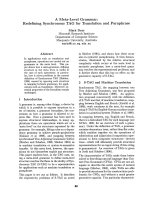
Figure 1: The configuration of a 4 ×4 MIMO OFDM testbed.
baseband signal sample rate and the short fixed OFDM frame
(45 OFDM symbols) adopted in the testbed, the channel state
and frequency offset during one OFDM frame per iod are re-
garded as invariable. We then adopt all 8 pilots for data trans-
mission and increase the data r a te by about 4%. (Even pilots
are also intended for tracking the phase n oise. We ignore its
impairments since our testbed use Agilent signal generators
whichhaveverylowphasenoise.)
In the meantime, the overhead in time domain due to
the use of CP is 256/320
= 80%, where an OFDM symbol
has 320 samples including a 64-sample CP. The testbed also
adopts a 4
× 4 configuration offering four times data rate
compared to a SISO system and the 64 quadrature ampli-
tude modulation (QAM). Finally, the actual peak data rate
is 35
× 6 × 4 × 200/256 × 256/320 = 525 Mbits/s and the
spectrum efficiency is 19.2 bits/Hz/s.
The configuration of the testbed, shown in Figure 1,con-
sists of four synchronized transmitters and four synchro-
nized receivers. At the transmitters, four Agilent ESG4438C
signal generators are employed to synchronously generate
four independent OFDM frames, each of which consists of
one short preamble, four long preambles used to MIMO
channel estimation and 40 payload symbols. The OFDM
frames are preloaded to the memories of the signal gener-
ators and are sent either in a burst mode or a continuous
mode. A trigger signal provided by an Agilent ESG4422 sig-
nal generator is used to initiate the MIMO transmission. The
receivers include low noise amplifies, RF down converters,
analog-to-digital converters (ADC), digital down converters
and PowerPC processors. An external clock is employed to
allow the four receivers to work synchronously. Four RF sig-
nals from four receive antennas are down converted and then
sampled by four ADCs. The sampled baseband signals are
passed to a computer as four indiv idual data files via a n Eth-
ernet interface. A MIMO OFDM demodulation program is
applied to recover the four independent user data streams.
The demodulation processing includes time synchroniza-
tion, frequency synchronization, channel estimation, FFT,
BLAST demodulation, and 64-QAM demapping. Their per-
formances and computation loads are discussed in [2].
The experiments were conducted in the second floor
of the Georgia Centers for Advanced Telecommunications
Te chnologies building located at 250 14th street, Atlanta,
Georgia. Figures 2 and 3 show the pictures of the transmit-
ters and receivers. Two uniform linear antenna (ULA) arrays,
consisting of four elements separated by three wavelengths,
are mounted at the transmitters and receivers, respectively.
Each element is a 2.4 GHz dual polarized (horizontal po-
larization and vertical polarization, linear) omni-directional
antenna covered by a radome. We select three typical loca-
tions to represent the common indoor wireless link scenar-
ios. The first place represents a line-of-sight (LOS) wireless
link within a typical laboratory. The second case is a non-
LOS wireless link blocked by a wall and the third is a non-
LOS wireless link from the laboratory to the corridor. All the
three positions are shown in Figure 4.
4 EURASIP Journal on Applied Signal Processing
Figure 2: The transmitters of the 4 ×4MIMOOFDMtestbed.
Figure 3:Thereceiversofthe4× 4MIMOOFDMtestbed.
3. THE CHARACTERISTICS OF MIMO
WIRELESS CHANNELS
We allocate the whole 27.3438 MHz bandwidth to 200 sub-
carriers and each subcarrier occupies 136.7 KHz bandwidth,
less than the coherence bandwidth of a typical indoor wire-
less channel. Then we assume that each subcarrier goes
through a flat fading channel and an one-tap f requency
equalizer for each subcarrier is sufficient to compensate the
channel distortions.
For a 4
×4 MIMO OFDM system, an OFDM sy mbol can
be expressed as follows,
r
k
= H
k
a
k
+ w
k
(k = 1, , 200), (1)
where r
k
= [r
1,k
, , r
4,k
]
T
, a
k
= [a
1,k
, , a
4,k
]
T
,andw
k
=
[w
1,k
, , w
4,k
]
T
are 4 × 1 receive signal, transmit signal,
and Gaussian noise vectors. The elements, r
i,k
, a
i,k
,andw
i,k
,
i
= 1, , 4, represent the receive signal, transmit signal,
and Gaussian noise at ith antenna over kth subcarrier, re-
spectively. H
k
is a 4 × 4 matrix, of which the element H
i, j,k
i, j = 1, , 4, represents the channel complex gain from the
jth transmitter to ith antenna over kth subcarrier. Normally,
we hav e E
{a
k
a
H
k
}=σ
2
s
I,andE{w
k
w
H
k
}=σ
2
0
I,whereI is
×
TX3
RX
×
×
TX1
TX2
×
Figure 4: The floorplan of the building in which the LOS and NLOS
measurements were made.
the 4 ×4 unit matrix and ( ·)
H
represents conjugate transpo-
sition. σ
2
s
and σ
2
o
are the QAM symbols average power and
noise variance. For 64-QAM modulation, we have σ
2
s
= 42.
The MIMO channel information is the decisive precon-
dition for BLAST modulation. The MIMO channel is es-
timated by using four long preambles as the training sig-
nals. The training signals are configured to form a unitary
matrix, expressed in the following equation. This configu-
ration can significantly simplify the computations because
time-consuming matrix inversion is replaced by simple ma-
trix transposition.
⎡
⎢
⎢
⎢
⎢
⎣
Tr
1,1
Tr
1,2
Tr
1,3
Tr
1,4
Tr
2,1
Tr
2,2
Tr
2,3
Tr
2,4
Tr
3,1
Tr
3,2
Tr
3,3
Tr
3,4
Tr
4,1
Tr
4,2
Tr
4,3
Tr
4,4
⎤
⎥
⎥
⎥
⎥
⎦
=
⎡
⎢
⎢
⎢
⎢
⎣
1 −1 −1 −1
111
−1
1
−111
11
−11
⎤
⎥
⎥
⎥
⎥
⎦
Pl,(2)
where Tr
i, j
is the jth training OFDM symbol at the ith trans-
mitter. Pl is the long preamble defined by the IEEE 802.16
standard [8].
Figure 5 shows an example of the measured 16-channel
frequency response position 1. For comparison, the channel
gains are normalized to eliminate the path loss. As we can see
from the figure, the channel responses exhibit evident fre-
quency selectivity.
In MIMO systems, the characteristics of the channel ma-
trix decide the system capacity. Let ρ
i,k
, i = 1, 2,3, 4, repre-
sent the ordered singular values of the channel matrix at kth
Weidong Xiang et al. 5
0
0.2
0.4
0.6
0.8
1
50 100 150 200 250
h11
(a)
0
0.2
0.4
0.6
0.8
1
50 100 150 200 250
h12
(b)
0
0.2
0.4
0.6
0.8
1
50 100 150 200 250
h13
(c)
0
0.2
0.4
0.6
0.8
1
50 100 150 200 250
h14
(d)
0
0.2
0.4
0.6
0.8
1
50 100 150 200 250
h21
(e)
0
0.2
0.4
0.6
0.8
1
50 100 150 200 250
h22
(f)
0
0.2
0.4
0.6
0.8
1
50 100 150 200 250
h23
(g)
0
0.2
0.4
0.6
0.8
1
50 100 150 200 250
h24
(h)
0
0.2
0.4
0.6
0.8
1
50 100 150 200 250
h31
(i)
0
0.2
0.4
0.6
0.8
1
50 100 150 200 250
h32
(j)
0
0.2
0.4
0.6
0.8
1
50 100 150 200 250
h33
(k)
0
0.2
0.4
0.6
0.8
1
50 100 150 200 250
h34
(l)
0
0.2
0.4
0.6
0.8
1
50 100 150 200 250
h41
(m)
0
0.2
0.4
0.6
0.8
1
50 100 150 200 250
h42
(n)
0
0.2
0.4
0.6
0.8
1
50 100 150 200 250
h43
(o)
0
0.2
0.4
0.6
0.8
1
50 100 150 200 250
h44
(p)
Figure 5: A measurement of 16-channel frequency responses at position 1.
subcarrier, that is, ρ
1,k
≥ ρ
2,k
≥ ρ
3,k
≥ ρ
4,k
. Then the condi-
tion number, c
k
,atkth subcarrier can be given as
c
k
=
ρ
1,k
ρ
4,k
. (3)
Figure 6 shows the condition numbers at different sub-
carriers associated with the MIMO channel shown in
Figure 5. We define the average condition number over all
the subcarriers as the condition number of a MIMO OFDM
system, which is given by following equation,
c
=
1
200
200
k=1
c
k
. (4)
The capacity for kth subcarrier and the total capacity over
allsubcarriersaregivenby
C
k
= W
k
log
2
det
I
4
+
SNR
4
H
k
H
H
k
,
C
=
200
k=1
C
k
,
(5)
where W
k
is the bandwidth of kth subcarrier and SNR is the
signal-to-noise ratio.
For a nonadaptive transmission, the channel status in-
formation is unknown to the transmitter and the transmit-
ted power is evenly allocated to all the subcarriers. Under the
condition, the MIMO channel with a lower condition num-
ber has a higher capacity. Particularly, when H
k
H
H
k
= 4I
4
,
the capacity C reaches its maximum value. That is,
C
max
= 4W log
2
(1 + SNR), (6)
where the W is the total bandwidth and W
= 200 × W
k
.
For this case, the singular values are ρ
i,k
= 2, i = 1, 2, 3, 4,
and the condition number is c
= 1. Figure 7 shows the sim-
ulation results and the fitting curve reflecting the variations
of the normalized capacity, C/C
max
, against the channel con-
dition numbers where the SNR
= 30 dB. The relationship
between the channel condition number and normalized ca-
pacity is not unique and determined because several MIMO
channel matrices could have similar condition numbers but
different system capacities. Statistically, the MIMO channel
6 EURASIP Journal on Applied Signal Processing
0
2
4
6
8
10
12
14
16
18
20
0 50 100 150 200 250
Figure 6: The condition numbers at different subcarriers for the
MIMO channels at position 1.
0
0.1
0.2
0.3
0.4
0.5
0.6
0.7
0.8
0.9
1
Normalized capacity
0 1020304050
Condition number
Simulation data
Fitting curve
Figure 7: The distribution of the normalized capacities versus the
channel condition numbers where the SNR
= 30 dB.
with a condition number of 10 reaches about 75% of the
maximum capacity.
Next, we observe the time variations of the MIMO chan-
nel. During the experiments, the transmitters and receivers
are fixed while some pedestrians were moving around.
Figure 8 shows the time variations of the condition num-
bers for the MIMO channels at the three different locations.
In order to observe the MIMO channel variation in a pe-
riod of several minutes, ten continuous MIMO channels are
extracted and recorded in an interval of about one minute
for each location. From Figure 8, we can see that the in-
door channel variations are much lower compared to out-
door channels and mainly caused by the movements of the
pedestrians and other inferences, like Bluetooth signals, and
microwave oven leakage. The MIMO channels at position 1
5
6
7
8
9
10
11
12
Condition number
12345678910
Time (min)
Position 1
Position 2
Position 3
Figure 8: The variations of channel condition number measured at
three different positions.
are with LOS link and have less variations comparing to po-
sition 2 and 3. On the other hand, the MIMO channels at
position 2 and 3 have NLOS links and lower condition num-
bers meaning larger capacities.
4. SYSTEM PERFORMANCE: BER-SNR CURVES
The BER-SNR curve is a critical performance for a wireless
communication system, which reflects the power efficiency.
A SISO OFDM system with 64-QAM modulation has the
same BER-SNR performance with single carrier system if the
errors introduced by the FFT/inverse FFT (IFFT) processing
are negligible. The BER-SNR curve of single carrier 64-QAM
systems is given by the following equation:
P
b
=
7
12
Q
2
7
E
b
N
0
,(7)
where Q(x)
= (1/
√
2π)
∞
x
e
−t
2
/2
dt, P
b
is the bit error prob-
ability, E
b
is signal energy per bit, and N
0
is power density
of Gaussian noise. It is quite predicable that a 4
× 4MIMO
OFDM system has a much larger BER than a SISO OFDM
system. The four transmitted signals are mixed with each
other during the propagation. When one of them is sepa-
rated during the demodulation, the others are presented as
additional noise.
Figure 9 gives the measured BER-SNR curves of the 4
×4
MIMO OFDM system at three locations shown in Figure 4.
The SNR varies from 0 dB to 40 dB, a reasonable upper
bound for an ac tual wireless system. Ten trials are measured
at each position. From the figure, we see that the 4
×4MIMO
OFDM system presents a quite fair BER-SNR performance.
This makes it imperative to adopt some advanced wireless
transmission schemes, like powerful coding, diversity and
adaptive modulation, to decrease the BER of MIMO wireless
link.
Weidong Xiang et al. 7
10
−4
10
−3
10
−2
10
−1
10
0
BER
0 5 10 15 20 25 30 35 40 45
E
b
/N
0
(dB)
Position 1
Position 2
Position 3
A4
× 4 MIMO OFDM system with 64-QAM
Figure 9: The BER-SNR curves measured at the three positions.
It is meaningful to compare the experimental data with
the simulation results derived from the MIMO channel
model which are applicable for indoor environments. In the
paper, we adopt the channel model suggested by the IEEE
802.11 task group [9]. To simulate the testbed configuration
at location 3, the following setups are used. Two ULA arrays
with four elements spaced by 3 wavelengths are adopted at
the transmitter and receiver. T he distance between the trans-
mitter and receiver are about 3 meters with non-LOS wireless
links. D model is selected representing a typical office or lab-
oratory environment. The pedestrians are moving around at
a speed of 1.2 Km/hr, while the fluorescent e ffects are con-
sidered as well. Figure 10 shows the comparisons of the mea-
sured BER-SNR curves with simulation results at location 3.
The performance match between the experimental data and
simulation results validate the efficiency of the MIMO chan-
nel model defined by [9] for an indoor environments with
the given bandwidth and frequency.
We investigate the degradation of the BER-SNR per-
formance caused by the estimation inaccuracy of MIMO
channel due to the finite resolution of ADC/DAC and the
unavoidable processing errors. Figure 11 shows the impair-
ments of BER-SNR performance caused by the inaccuracy of
channel estimation. Assume that the estimated channel com-
plex gain is
h = h + αζ, where the h is the real channel com-
plex gain, α is a factor, and ζ is a complex Gaussian variable
with zero mean and a variance of 1. The relative channel in-
accuracy is defined by d
= α
2
/|h|
2
× 100%. The results show
that the MIMO OFDM systems are susceptible to channel es-
timation inaccuracy. A channel estimate with an inaccuracy
of less than 0.01% is required for a 4
× 4MIMOsystem.
5. THE IMPACTS OF CARRIER FREQUENCY OFFSET
Carrier frequency offset is a common misalignment for wire-
less communications systems that caused by the frequency
10
−4
10
−3
10
−2
10
−1
10
0
BER
0 5 10 15 20 25 30 35 40 45
E
b
/N
0
(dB)
Position 3
Simulations
A MIMO OFDM system with 64-QAM
Figure 10: The comparison of BER-SNR curves from measure-
ments and simulations.
10
−4
10
−3
10
−2
10
−1
10
0
BER
0 5 10 15 20 25 30 35 40 45
E
b
/N
0
(dB)
1%
0.1%
0.0316%
0.01%
Perfect channel estimate
A MIMO OFDM system with 64-QAM
Figure 11: The requirements of the accuracy of the channel esti-
mate. (Based on the MIMO channels at position 1.)
drifts between the local oscillators at transmitters and re-
ceivers. The frequency offset breaks the orthogonal condition
between the subcarriers which decreases the amplitude of the
wanted signal and introduces additional intercarrier inter-
ferences (ICI). The frequency offset results in an additional
signal-to-interference ratio (SIR) equivalently. In the view of
the demodulated QAM symbol constellations, the frequency
offset leads to rotation of the constellations from their ideal
positions in a direction decided by the sign of the frequency
offset. Figure 12 gives an example of the demodulated QAM
symbols distorted by a carrier frequency offset of 0.05, where
the frequency offset is normalized by the subcarrier spacing.
The impairments of carrier frequency offset are distinct from
8 EURASIP Journal on Applied Signal Processing
−10
−8
−6
−4
−2
0
2
4
6
8
10
−10 −50 510
Figure 12: The impacts on constellations for 64-QAM systems
when a carrier frequency offsetof0.05ispresented.
10
−4
10
−3
10
−2
10
−1
10
0
BER
0 5 10 15 20 25 30 35 40 45
E
b
/N
0
(dB)
0.05
0.04
0.03
0.02
0.01No frequency offset
A MIMO OFDM system with 64-QAM
Figure 13: The impacts on the BER-SNR curves of the carrier fre-
quency offsets at the position 1.
Gaussian noise and cannot be compensated for by simply in-
creasing the transmitted power. The receiver has to detect
the carrier frequency offset and compensate for the distor-
tions in either frequency domain or time domain. Figure 13
shows the BER-SNR performance degradations against car-
rier frequency offset. It is easy to see that the BER-SNR
curves of MIMO systems demonstrate a high sensitivity to
frequency offset when compared to SISO systems. As we can
see from Figure 13, the 4
× 4 MIMO OFDM systems require
frequency synchronization with an offset less than 0.01, that
is 1.367 KHz.
6. ASYMMETRIC MIMO SYSTEM: THE PERFORMANCE
OF A 3
× 4 MIMO OFDM SYSTEM
The sensitivity of the performance of MIMO OFDM systems
to channel estimation inaccuracy and frequency offset creates
10
−4
10
−3
10
−2
10
−1
10
0
BER
0 5 10 15 20 25 30 35 40
E
b
/N
0
(dB)
Using 1, 3, 4receivers
4
× 4MIMO
Using 1, 2, 3receivers
Using 2, 3, 4receivers
Using 1, 2, 4receivers
A MIMO OFDM system with 64-QAM
Figure 14: The BER-SNR curves of the suggested 3 ×4 asymmetric
MIMO OFDM system.
challenges to establish low-cost commercial MIMO OFDM
systems. In the meantime, the capacities of MIMO systems
vary with the MIMO channel statuses. All of these provide
the researchers a host of new research topics.
Here we propose an asymmetric MIMO system config-
uration to take the advantage of redundant receive signals.
A three-transmitter four-receiver (3
× 4) MIMO system is
constructed by simply turning off one of the transmitters.
In such a case, there are four receive signals, generating four
choices to select three of them. The receiver compares and se-
lects the three signals that give a lowest BER. A 3
× 4MIMO
OFDM system offers an improved BER-SNR performance
statistically compared to a 3
× 3 MIMO system with a data
rate of 393.75 Mb/s. Figure 14 gives the four BER-SNR curves
at location 1 and the one with lowest BER is selected. This is a
simple selective diversity scheme for asymmetric MIMO sys-
tems.
Furthermore, we introduce a so-called forward estimate
BLAST demodulation method to asymmetric MIMO systems.
The MIMO channel condition number reflects the system
capacity roughly and the computation loads for calculating
singular values are much less than the BLAST demodulation.
Approximately, the singular values can be acquired during
the singular value decomposition (SVD) of the channel ma-
trix, w hich is part of the processing of channel matrix in-
version. For typical order decision feedback (ODF) BLAST
method, the computation includes three times of order de-
cision, channel matrix inversion, and matrix multiplication.
To avoid three times repeat of the BLAST demodulation,
we compare the condition numbers of all the four 3
× 3
MIMO combinations before the BLAST modulation and se-
lect the configuration with smallest condition number, which
is shown in Figure 15. Table 2 lists the four combinations and
related condition numbers, where the combination of #2, #3,
and #4 receivers give the smallest condition number of 4.5
Weidong Xiang et al. 9
Recevier #1
Recevier #2
Recevier #3
Recevier #4
Data file
#1
Data file
#2
Data file
#3
Data file
#4
3/4 selector
by comparing
the condition
numbers
3
× 3
BLAST
demodulation
Figure 15: The diagram of the suggested 3 ×4 asymmetric MIMO OFDM system.
Table 2: The combinations and related condition numbers.
Selection Condition number
#1, #2, and #3 receivers 6.2
#1, #2, and #4 receivers 9.3
#1, #3, and #4 receivers 7.1
#2, #3, and #4 receivers 4.5
and is selected. From the results, the selected configuration
provides a gain of 3–10 dB comparing to the others.
Compared to the other advanced wireless transmission
techniques, like coding and adaptive modulation, the asym-
metric MIMO scheme is regarded as a cost-effective solution
since it only requires one or more additional RF receivers and
a selection algorithm. Whereas a powerful coding likely re-
duces the achievable data rate as well as results in large pro-
cessing latency. And an adaptive transmission requires com-
plex parameter estimation, prompt, and accurate feedback
and duplex channel.
7. CONCLUSION
A4
× 4 MIMO OFDM indoor wireless communication
testbed is set up, which offers a peak data rate of 525 Mb/s
with a spectral efficiency of 19.2 bits/Hz/s. The experiment
results verify the feasibility to achieve extreme high data rate
by adopting MIMO and OFDM par allel transmission tech-
nologies. The match of the experiment data and simulation
validates the efficiency of the channel model defined by IEEE
802.11 study g roup for indoor MIMO channels at center fre-
quency of 2.435 GHz with a bandwidth about 27 MHz.
In the meantime, the experimental results demonstrate
the BER-SNR performance of the MIMO OFDM systems is
quite fair and susceptible to the various misalignments, such
as frequency offset and channel estimation inaccuracy. The
enabling technologies, such as coding, diversity, and adap-
tive transmission, are needed to decrease the BER of MIMO
wireless link.
An asymmetric MIMO scheme is proposed as a cost-
effective way to improve the BER-SNR performance. This
scheme is suitable for low-cost commercial products. An ef-
ficient scheme that optimally combines all the four received
signals will be studied.
REFERENCES
[1] G. D. Golden, C. J. Foschini, R. A. Valenzuela, and P. W. Wolni-
ansky, “Detection algorithm and initial laboratory results using
V-BLAST space-time communication architecture,” Electronics
Letters, vol. 35, no. 1, pp. 14–16, 1999.
[2] W. Xiang, D. Waters, T. G. Pratt, J. Barry, and B. Walken-
horst, “Implementation and experimental results of a three-
transmitter three-receiver OFDM/BLAST testbed,” IEEE Com-
munications Magazine, vol. 42, no. 12, pp. 88–95, 2004.
[3] W. Xiang, T. Pratt, and X . Wang, “A software radio testbed for
two-transmitter two-receiver space-time coding OFDM wire-
less LAN,” IEEE Communications Magazine,vol.42,no.6,pp.
S20–S28, 2004.
[4] H. Sampath, S. Talwar, J. Tellado, V. Erceg, and A. Paulraj, “A
fourth-generation MIMO-OFDM broadband wireless system:
design, performance, and field trial results,” IEEE Communica-
tions Magazine, vol. 40, no. 9, pp. 143–149, 2002.
[5] R. J. Piechocki, P. N. Fletcher, A. R. Nix, C. N. Canagarajah,
and J. P. McGeehan, “Performance evaluation of BLAST-OFDM
enhanced Hiperlan/2 using simulated and measured channel
data,” Electronics Letters, vol. 37, no. 18, pp. 1137–1139, 2001.
[6] M. D. Batariere, J. F. Kepler, T. P. Krauss, S. Mukthavaram, J.
W. Porter, and F. W. Vook, “An ex per imental OFDM system
for broadband mobile communications,” in Proceedings of 54th
IEEE Vehicular Technology Conference (VTC ’01), vol. 4, pp.
1947–1951, Atlantic City, NJ, USA, October 2001.
[7] J.W.Wallace,B.D.Jeffs, and M. A. Jensen, “A real-time multi-
ple antenna element testbed for MIMO algorithm development
and assessment,” in Proceedings of IEEE Antennas and Propa-
gation Society International Symposium , vol. 2, pp. 1716–1719,
Monterey, Calif, USA, June 2004.
[8] IEEE P802.16a/D4-2002, “Part 16: Air interface for fixed broad-
band wireless access systems,” 2002.
[9] L. Schumacher, “WLAN MIMO Channel Matlab Program,”
download information: />∼lsc/Re-
search/IEEE
80211 HTSG CMSC/distribution terms.html.
10 EURASIP Journal on Applied Signal Processing
Weidong Xiang received his M.S.E.E. and
Ph.D. degrees from Tsinghua University,
Beijing, China, in 1996 and 1999, respec-
tively. From 1999 to 2004, he worked as
a Postdoctoral Fellow and then Research
Scientist in the Software Radio Laboratory
(SRL) at Georgia Institute of Technology,
Atlanta, USA. In September 2004, he joined
the ECE Department, University of Michi-
gan, Dearborn, as an Assistant Professor.
His research interests include high-speed wireless LAN prototype
integrating MIMO, OFDM, software radio, and smart antenna,
wireless access for vehicular environments (WAVE), ultrawide band
(UWB), and real-time wireless control network.
Paul Richardson is an Associate Professor
in the Department of Elect rical and Com-
puter Engineering, University of Michigan,
Dearborn. He is a Principal Investigator for
ultrawideband applications with the U.S.
Army Research Development and Engineer-
ing Center, Warren, Mich, and a Consultant
for the United States Marine Corps regard-
ing command and control networks. He re-
ceived the B.S.E. degree in computer engi-
neering, the M.S.E. degree in computer and elect rical engineering,
and the Ph.D. degree in systems engineering, all from Oakland Uni-
versity, Rochester, Mich. His interests include embedded real-time
systems, vehicular networks and communications systems, and ul-
trawideband applications.
Brett Walkenhorst received the B.S. and
M.S. degrees in electrical engineering from
Brigham Young University (BYU), Provo,
UT, in 2001. From 2001 to 2003, he worked
as a Design Engineer at Lucent Technolo-
gies, Bell Laboratories, Denver, Colo. He is
currently a Research Engineer at the Geor-
gia Tech Research Institute in Atlanta, Ga.
His research interests include signal pro-
cessing for wireless communications, elec-
tromagnetic theory, channel estimation, and neural networks.
Xudong Wang received the Ph.D. degree
from Georgia Institute of Technology in
2003. He also received his B.E. and Ph.D.
degrees from Shanghai Jiao Tong Univer-
sity, Shanghai, China, in 1992 and 1997, re-
spectively. From 1998 to 2003, he was with
the Broadband and Wireless Networking
(BWN) Lab at Georgia Institute of Technol-
ogy. Currently, he is a Senior Research En-
gineer with Kiyon, Inc., where he leads re-
search and development of MAC and routing protocols for wireless
mesh networks. His research interests also include software radios,
cross-layer design, and communication protocols for cellular, mo-
bile ad hoc, sensor, and ultrawideband networks. He has served as
a technical committee member for many international conferences,
and has been a technical reviewer for numerous international jour-
nals and conferences. He has two patents pending in wireless mesh
networks. He is a Member of IEEE, ACM, and ACM SIGMOBILE.
Thomas Pratt received the B.S. degree from
the University of Notre Dame, Notre Dame,
Ind, in 1985, and the M.S. and Ph.D. de-
grees in electrical engineering from the
Georgia Institute of Technology, Atlanta,
in 1989 and 1999, respectively. He heads
the Software Radio Laboratory at Georgia
Tech, where research has focused princi-
pally on MIMO-OFDM, space-time adap-
tive processing, WLAN interference sup-
pression, multiple-antenna architectures, channel modeling, and
mobile communications. He is a Principal Research Engineer at the
Georgia Tech Research Institute.