Báo cáo hóa học: " Multilevel Codes for OFDM-Like Modulation over Underspread Fading Channels" pot
Bạn đang xem bản rút gọn của tài liệu. Xem và tải ngay bản đầy đủ của tài liệu tại đây (1.83 MB, 19 trang )
Hindawi Publishing Corporation
EURASIP Journal on Applied Signal Processing
Volume 2006, Article ID 97210, Pages 1–19
DOI 10.1155/ASP/2006/97210
Multilevel Codes for OFDM-Like Modulation over
Underspread Fading Channels
Siddhartha Mallik and Ralf Koetter
The Coordinated Science Laborator y, University of Illinois at Urbana-Champaign, Urbana, IL 61801, USA
Received 7 June 2005; Revised 3 May 2006; Accepted 12 May 2006
We study the problem of modulation and coding for doubly dispersive, that is, time and frequency selective, fading channels.
Using the recent result that underspread linear systems are approximately diagonalized by biorthogonal Weyl-Heisenberg bases,
we arrive at a canonical formulation of modulation and code design. For coherent reception with maximum-likelihood decoding,
we derive the code design criteria as a function of the channel’s scattering function. We use ideas from generalized concatenation to
design multilevel codes for this canonical channel model. These codes are based on partitioning a constellation carved out from the
integer lattice. Utilizing the block fading interpretation of the doubly dispersive channel, we adapt these partitioning techniques to
the richness of the channel. We derive an algebraic framework which enables us to partition in arbitrarily large dimensions.
Copyright © 2006 S. Mallik and R. Koetter. This is an open access article distributed under the Creative Commons Attribution
License, which permits unrestricted use, distribution, and reproduction in any medium, provided the original work is properly
cited.
1. INTRODUCTION
The design of reliable, high data rate mobile wireless commu-
nications systems has been an area of tremendous research
activity for the last couple of years. New developments in the
field of channel modeling, signaling, and code design have
enabled technologies that support high data rates in a wire-
less setting which in turn have fueled consumer interest in
adoption and utilization of wireless devices a nd services.
This paper deals with communication over rapidly time-
varying channels, that is, channels which cannot be regarded
as time-invariant over a frame. In a typical wireless set-
ting, a signal sent from the transmitter reaches the receiver
through multiple paths, collectively termed as multipath.In-
terference among the multiple paths results in a decrease in
signal amplitude. Further due to the time-varying nature of
the medium, the received signal amplitude varies with time,
in other words, the signal undergoes fading. The primary
means of combating fading is through diversity,inwhich
copies of the transmitted message are made available on
different dimensions (time, frequency, or space) to the re-
ceiver. All wireless communications schemes utilize tempo-
ral diversity by using sophisticated channel coding in con-
junction with interleaving to provide replicas of the trans-
mitted signal in the temporal domain. Frequency diversity
techniques employ the fact that waves transmitted on differ-
ent frequencies induce different multipath structure in the
propagation media. In space or antenna diversity spatially
separate antennas are used at the transmitter or the receiver
or both. Communication schemes should utilize all avail-
able forms of diversity to ensure adequate performance. In
this paper we utilize time and frequency diversity by design-
ing an OFDM-like signaling scheme to be used in conjunc-
tion with a multilevel coding scheme easily adapted for fad-
ing.
To implement a n OFDM-like framework over channels
that fade in time and frequency, also called doubly dispersive
channels, we need signaling waveforms to be well localized
in time and frequency. The good localization in frequency
is desirable, so that the waveform sees a frequency nonse-
lective channel. At the same time good localization in time
is also desirable as it mitigates the effect of temporal varia-
tions in the channel. In [1, 2], a class of waveforms known
as the Weyl-Heisenberg bases were found to be suitable can-
didates as signaling waveforms. These biorthogonal bases are
obtained by time and frequency shifts of a given prototype
pulse. The time shift T and the frequency shift F are usually
chosen such that TF > 1 so as to minimize the interference
at the receiver. On the other hand if maximum spectral effi-
ciency is required, the parameters T and F are chosen such
that TF
= 1 at the expense of interference at the receiver.
In this case an interference cancellation technique at the re-
ceiver can be used to cancel o ut the intersymbol interference.
Such a scheme is outlined in [3].
2 EURASIP Journal on Applied Signal Processing
Both approaches mentioned above finally lead to an iden-
tical canonical vector fading channel model in discrete time
given by y
k
= h
k
x
k
+ n
k
, k = 1, , D,whereD is the num-
ber of dimensions we are coding over, y
k
, h
k
, x
k
,andn
k
are the received signal, fading realization, t ransmitted sig-
nal, and noise realization in dimension k. Powerful coding
schemes have been proposed for this channel in the liter-
ature. In [4], high diversity constellations are constructed
by applying the canonical embedding to the ring of inte-
gers of an algebraic number field. In [5], higher diversity
is obtained by applying rotations to a classical signal con-
stellation so that any two points achieve a maximum num-
ber of distinct components. Another approach is taken by
bit-interleaved coded modulation (BICM) [6], where bit-
wise interleaving at the encoder input is u sed to improve
the performance of coded modulation on fading channels.
In this paper, we propose a multilevel coded modulation
scheme for the canonical channel model described above.
This scheme is reminiscent of Ungerboeck’s trellis-coded
modulation [7]. We develop new partitioning techniques for
integer lattices which are particularly well suited for fading
channels.
The main contribution of this paper is as follows. We
use results from linear operator theory and harmonic anal-
ysis to study coding and modulation design for underspread
time-varying fading channels. Using the fact that under-
spread channels are approximately diagonalized by biorthog-
onal Weyl-Heisenberg bases, we arrive at a canonical formu-
lation of modulation and code design. For a coherent re-
ceiver employing maximum-likelihood decoding, we derive
the code-design criteria as a function of the channel’s scat-
tering function. We provide expressions for the maximum
achievable diversity order as a function of the channel’s scat-
tering function. Secondly, for this canonical channel, we pro-
pose new multilevel codes based on partitioning a signal con-
stellation carved out from the integer lattice
Z
n
. We use ideas
from generalized concatenation to derive new set partition-
ing techniques for the fading channel. We also provide an al-
gebraic framework which enables us to partition signal con-
stellations in arbitrarily large dimensions.
This paper is organized as follows. In Section 2 we in-
troduce the time-vary ing fading channel and the OFDM-
like modulation scheme. In Section 3 we derive the code
design criteria and make certain critical observations on
the code-design problem for this channel. In Section 4,we
describe our set partitioning techniques for fading chan-
nels and use it to construct a multilevel coded modulation
scheme. Section 5 contains performance plots and discusses
how the coding scheme is adapted to the channel. Section 6
contains some concluding remarks.
2. UNDERSPREAD TIME-VARYING FADING CHANNELS
In this section, we introduce the time-frequency selective
fading channel model, discuss the consequences of the un-
derspread assumption, introduce our modulation scheme
based on biorthogonal Weyl-Heisenberg bases, and provide
the canonical channel representation.
2.1. Time-frequency selective fading channels
We model the mobile as a linear time-variant system with
input-output relationship given by
y(t)
= ( Hx)(t)+n
w
(t) =
t
h(t, t
)x(t
) dt
+ n
w
(t), (1)
where x(t) is the transmitted signal, y(t) is the received sig-
nal, H is the linear operator describing the effect of the chan-
nel, h(t, t
) is the kernel of the channel, and n
w
(t)iszero-
mean circularly symmetric complex white Gaussian noise.
Throughout this paper, we assume that h(t, t
) is a complex
Gaussian process in t and t
. The time-varying transfer func-
tion of the channel is defined as [ 8]
L
H
(t, f ) =
τ
h(t, t − τ)e
−j2πfτ
dτ. (2)
Note that in the time-invariant case where h(t, t
− τ) = h(τ)
the time varying transfer function reduces to the ordinary
transfer function, that is, L
H
(t, f )=
τ
h(τ)e
−j2πfτ
dτ =H( f ).
An alternative representation of the input-output relation (1)
is
y(t)
=
τ
ν
S
H
(ν, τ)x(t − τ)e
j2πνt
dν dτ,(3)
where S
H
(ν, τ) is the channel’s delay-Doppler spreading func-
tion which is related to the impulse response h(t, t
− τ)
through a Fourier transform as
S
H
(ν, τ) =
t
h(t, t − τ)e
−j2πνt
dt. (4)
We invoke a wide-sense stationary uncorrelated scatter-
ing (WSSUS) assumption which is
E
H
S
H
(ν, τ)
= 0,
E
H
S
H
(ν, τ)S
∗
H
(ν
, τ
)
=
C
H
(ν, τ)δ(ν − ν
)δ(τ −τ
),
(5)
where C
H
(ν, τ) ≥ 0 denotes the scattering function of the
channel [9, Section 14.1]. Equivalently, the WSSUS assump-
tion implies that the autocorrelation function of the impulse
response h(t, t
− τ) has the following structure:
E
H
h(t, t − τ)h
∗
(t
, t
− τ
)
= φ
H
(t − t
, τ)δ(τ −τ
).
(6)
Thus under this model, the channel taps are uncorrelated
(but not necessarily i.i.d), and the temporal variations are
wide-sense stationary. Finally, we will need the channel’s cor-
relation function defined as
E
H
L
H
(t, f )L
∗
H
(t
, f
)
= R
H
(t − t
, f − f
), (7)
with the Fourier correspondence
R
H
(Δt, Δ f ) =
τ
ν
C
H
(ν, τ)e
j2π(νΔt−τΔ f )
dτ dν. (8)
S. Mallik and R. Koetter 3
10
6
Channel correlation function
1
0.9
0.8
0.7
0.6
0.5
0.4
0.3
0.2
0.1
R
H
(Δt, Δ f )
1.5
1
0.5
0
0.5
1
1.5
Δ f (Hz)
0.02
0.01
0
0.01
0.02
Δt (s)
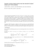
Figure 1: Amplitude of the channel correlation function for the
Jakes/exponential scattering function. Parameters ν
m
= 50 Hz, τ
0
=
10
−6
Hz.
In literature, it is fairly common to assume that the scattering
function has a product form, that is, C
H
(ν, τ) = f (τ)g(ν), for
example,
C
H
(ν, τ) =
⎧
⎪
⎪
⎨
⎪
⎪
⎩
ke
−τ/τ
0
1
πν
m
1 −
ν/ν
m
2
if |ν|≤ν
m
, τ ≥ 0,
0 otherwise,
(9)
where α>0. This part icular scattering function is called the
exponential/Jakes scattering function. Figure 1 is a plot of the
above correlation function. The function is normalized, that
is, R
H
(0, 0) = 1.
2.2. The underspread assumption and
its consequences
A fundamental classification of WSSUS channels is into un-
derspread and overspread [9, Section 14.1]. A channel is un-
derspread if its scattering function is highly concentrated
around the origin. Note that for simplicity we assume that
the scattering function is centered around τ
= 0, which
means that any potential overall delay τ>0 has been split
off from the channel. A common assumption is that the scat-
tering function is compactly supported within the rectangle
[
−τ
0
, τ
0
]×[−ν
0
, ν
0
] around the origin of the (τ, ν) plane, that
is,
C
H
(ν, τ) = 0for(τ, ν) ∈
− τ
0
, τ
0
×
−
ν
0
, ν
0
. (10)
Thus the delay spread and Doppler spread are assumed to
be bounded. Defining the channel’s spread as the area of this
rectangle, σ
H
= 4τ
0
ν
0
, the channel is said to be underspread
if σ
H
≤ 1 and overspread otherwise. The underspread as-
sumption is relevant as most mobile radio channels are un-
derspread .
As explained in [10] there exist alternative ways to char-
acterize the concentration of the scattering function that
avoid the assumption of compact support. These involve the
weighted
m
(φ)
H
of the scattering function which are defined as
m
(φ)
H
=
∞
−∞
φ(τ, ν)C
H
(ν, τ) dτ dν
∞
−∞
C
H
(ν, τ) dτ dν
, (11)
where φ(τ, ν)
≥ 0 is a weighting function that satisfies
φ(τ, ν)
≥ φ(0, 0) = 0 and penalizes scattering function com-
ponents lying away from the origin. Special cases are the
moments obtained with the weighing functions φ
k,l
(ν, τ) =
|
ν|
l
|τ|
k
with k, l ∈N. Within this framework, a WSSUS chan-
nel is called underspread if specific moments and weighted
integrals are small.
An important result we are going to build our develop-
ment on is the fact that underspread systems are approxi-
mately diagonalized by biorthogonal Weyl-Heisenberg bases
[1, 2]. The Weyl-Heisenberg bases are obtained by time-
frequency shifting two nor malized functions g(t)andγ(t)
that have good time-frequency localization,
g
k,l
(t) = g( t −kT)e
j2πlFt
, γ
k,l
(t) = γ(t − kT)e
j2πlFt
,
(12)
where T denotes the time separation and F denotes the fre-
quency separation between the basis functions. The parame-
ters T and F are chosen such that TF
≥ 1. These bases satisfy
the biorthogonality condition,
g
k,l
, γ
k
,l
=
t
g
k,l
(t)γ
∗
k
,l
(t)dt = δ(k − k
)δ(l − l
).
(13)
Choosing T
≤ 1/2ν
0
and F ≤ 1/2τ
0
, the kernel h(t, t
) of the
underspread fading channel can be well approximated as
h(t, t
) =
∞
k=−∞
∞
l=−∞
L
H
(kT, lF)g
k,l
(t)γ
∗
k,l
(t
). (14)
Details on the choice of g(t)andγ(t)canbefoundin
[1, 2]. The correlation function of the expansion coefficients
L
H
(kT, lF) is given by sampling the channel correlation func-
tion
E
L
H
(kT, lF)L
∗
H
(k
T, l
F)
= R
H
(k − k
)T,(l − l
)F
.
(15)
2.3. Modulation scheme
The diagonalization of underspread systems by the Weyl-
Heisenberg bases naturally suggests using an OFDM-like
modulation scheme for communication over underspread
channels [11]. The tr ansmit signal x(t)isgivenby
x( t)
=
∞
k=0
M
−1
l=0
E
s
c
k,l
g
k,l
(t), (16)
where the c
k,l
are the information bearing data symbols, M is
the number of OFDM tones, and E
s
is an energy normaliza-
tion factor. Using (1), (13), and (16), the received signal y(t)
4 EURASIP Journal on Applied Signal Processing
is given by
y(t)
=
t
h(t, t
)x(t
)dt
+ n
w
(t)
=
t
∞
k=−∞
∞
l=−∞
L
H
(kT, lF)g
k,l
(t)γ
∗
k,l
(t
)x(t
)dt
+ n
w
(t)
=
∞
k=0
M
−1
l=0
L
H
(kT, lF)
E
s
c
k,l
g
k,l
(t)+n
w
(t).
(17)
The receiver computes the inner products y
k,l
,
y
k,l
=
t
y(t)γ
∗
k,l
(t)dt = L
H
(kT, lF)
E
s
c
k,l
+ w
k,l
, (18)
where w
k,l
=
t
n
w
(t)γ
∗
k,l
(t)dt. Since the signals γ
k,l
(t)arenot
orthogonal, there is some correlation between the noise co-
efficients w
k,l
. The noise correlation is ignored and the noise
variance is upper bounded using the upper Riesz constant B
f
[11], that is, we assume E[w
k,l
w
k
,l
] = B
f
σ
2
δ(k −k
)δ(l −l
),
where σ
2
is the power spectral density of the white Gaussian
noise process n
w
(t). We note that the parameters T and F are
typically chosen such that TF > 1isassmallaspossiblein
order to maximize the spectral efficiency. Consequently (14)
yields an oversampled representation of the channel.
Some parallels can be drawn with discrete time channel
models. Consider the channel model given y
= Hx+w,where
w, y
∈ C
MN
are the noise vector and the received channel
vector, respectively, x
∈ C
MN
is the transmitted signal vector
and H is the random channel matrix. Let H
= UDV be the
singular value decomposition of H. If the channel is known
then the transmitter spreads signals across the right singular
vectors V, and the receiver correlates across the left singu-
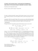
lar vectors U. This is analogous to transceiver architecture of
Figure 2.Asmentionedin(14), the underspread assumption
implies that a particular choice of U and V, viz., the Weyl-
Heisenberg bases, enables the diagonalization of the channel
even when the channel is unknown at the transmitter.
2.4. The canonical channel model
Let
y
k
= (y
k,0
, y
k,1
, , y
k,M−1
)
T
, h
k,l
= L
H
(kT, lF), h
k
=
(h
k,0
, h
k,1
, , h
k,M−1
)
T
, c
k
= (c
k,0
, c
k,1
, , c
k,M−1
)
T
,and
w
k
= (w
k,0
, w
k,1
, , w
k,M−1
)
T
, where (·)
T
and (·)
∗
denote
the transpose operator and the conjugate transpose opera-
tor, respectively. The equivalent complex baseband discrete
time vector channel model is then given by
y
k
=
E
s
h
k
c
k
+ w
k
, k ∈ Z, c
k
∈ C
M
, (19)
where
denotes the component-wise product of two vec-
tors. The noise w
k,l
and the channel gains h
k,l
are zero mean,
circularly symmetric, complex Gaussian random variables
with E[
w
k
w
∗
k
] = 2σ
2
I
M×M
and E[h
k,l
, h
∗
k
,l
] = R
H
((k − k
)T,
(l
− l
)F).
Equation (19) represents a set of parallel, correlated (in
time and frequency) discrete time Rayleigh fading channels.
Thus making use of the important result that underspread
time-varying systems are approximately diagonalized by
Weyl-Heisenberg bases, the OFDM-like modulation scheme
allows us to formulate the code-design problem in a canoni-
cal domain.
It may be argued that the use of biorthogonal Weyl-
Heisenberg bases is unnecessary. In particular, for extremely
underspread channels of the form depicted in Figure 1 (with
aspreadfactorof5
×10
−5
), orthogonal basis functions would
not suffer much in terms of interference as compared to
biorthogonal basis functions [3]. Since the same bases are
used at the transmitter and the receiver, the complexity of
an orthogonal scheme would be lower. The key point is that,
both approaches would result in the same canonical chan-
nel model. In particular, an interference cancelling technique
mentioned in [3] may be used to cancel out any intersy mbol
or intercarrier interference resulting due to the use of orthog-
onal basis functions.
3. CODE DESIGN CRITERIA
In this section we consider a block-coded modulation
scheme. We derive an expression for the pairwise error prob-
ability assuming maximum-likelihood decoding and perfect
channel state information at the receiver. Using the expres-
sion for the pairwise error probability as a starting point, we
develop a framework for designing codes for the canonical
channel described by (19).
3.1. The block-coded modulation scheme
We consider a block-coded modulation scheme where a
codeword spans M tones and N time slots; that is, we code
across time and frequency so as to exploit time-frequency
diversity. A codeword c
= (c
T
1
, c
T
2
, , c
T
M
−1
)
T
is an NM-
dimensional vector obtained by stacking M column vectors
c
k
,eachoflengthN. Similarly, vectors y, h,andw are given
by y
= (y
T
0
, y
T
1
, , y
T
M
−1
)
T
, h = (h
T
0
, h
T
1
, , h
T
M
−1
)
T
,and
w
= (w
T
0
, w
T
1
, , w
T
M
−1
)
T
.From(19), the received vector y
is given by
y
=
E
s
h c + w. (20)
Because of assumptions made in Section 2.1, h and w are
zero mean, circularly symmetric, complex Gaussian vectors
with correlation matrices R
= E[hh
∗
]andE[ww
∗
] =
2σ
2
I
NM×NM
. As a result, the received vector y is conditioned
on the transmitted codeword c and the channel state h is also
complex Gaussian.
The following proposition gives the Chernoff upper
bound on the pairwise error probability of this block-coded
modulation scheme. In the proposition, the quantity n equals
MN.
Proposition 1. Let h, w
∈ C
n
be circularly symmetric,
complex Gaussian random vectors with R
= E[hh
∗
] and
E[ww
∗
] = 2σ
2
I
n×n
.Let
E
s
be an energy normalization factor
and let ρ E
s
/8σ
2
. Let c
(i)
and c
( j)
be two sig nal points in sig-
nal constellation M which consists of points in
C
n
.Letα be the
S. Mallik and R. Koetter 5
Transmitte r
c
k,0
g(t)
c
k,1
g(t)e
j2πFt
c
k,N 1
g(t)e
j2π(N 1)Ft
Channel
+
s(t)
H
H
s
(t)
Receiver
γ(t)
γ(t)e
j2πFt
γ(t)e
j2π(N 1)Ft
y
k,0
y
k,1
y
k,N 1
Figure 2: The transmitter/receiver structure of the OFDM-like system.
difference vector between these two points, that is, α = c
(i)
−c
( j)
.
Further, Z
= [ z
ij
] is an n ×n diagonal matrix with z
ii
=|α
i
|
2
.
The pairwise error probability P(c
(i)
→ c
( j)
) for two signal
points c
(i)
, c
( j)
∈ M transmitted over the correlated Rayleigh
fading channel
y
=
E
s
h c + w (21)
is upper bounded by
P
c
(i)
−→ c
( j)
≤
1
det(I + ρRZ)
(22)
=
n
i=1
1
1+ρλ
i
, (23)
where λ
i
≥ 0 are the eigenvalues of RZ.
Proof. The proof is straightforward. See for example [12, the
appendix]. A proof appears in the appendix of this paper for
the sake of completeness.
3.2. The role of deep fades in pairwise error probability
We begin by first deriving a lower bound on the pairwise er-
ror probability. It is straightforward to show that the pairwise
error probability is given by the following expression:
P
c
(i)
−→ c
( j)
= E
h
Q
E
s
4σ
2
h
∗
Zh
, (24)
where Q(x) is the Q function which is defined as Q(x)
=
(1/
√
2π)
∞
x
e
x
2
/2
dx.
Consider the following approximation to the Q function.
Let
Q(x) =
⎧
⎨
⎩
Q(1), x ≤ 1,
0 otherwise.
(25)
Since
Q(x) ≤ Q(x)forallx, it follows that
P
c
(i)
−→ c
( j)
≥
E
h
Q
E
s
4σ
2
h
∗
Zh
=
Q(1)P
h
∗
Zh ≤
2
ρ
.
(26)
We will consider two extreme cases of correlated fading, viz.,
independent and identically distributed (i.i.d) fading and
block fading. A more comprehensive treatment appears in
[13] where this idea of behavior at origin and diversity has
been generalized to arbitrary fading distributions. The fad-
ing is said to be i.i.d if h
i
are independent and identically dis-
tributed that is, R
= E[hh
∗
] = I
NM×NM
.Thechannelissaid
to undergo block fading if h
i
are completely correlated, that
is, h
1
= h
2
=···=h
n
.
We first consider the i.i.d fading scenario. Let β
= (β
1
,
β
2
, , β
n
) be a permutation of the entries of the vector α =
(|α
1
|
2
, |α
2
|
2
, , |α
n
|
2
) such that the entries of β are arranged
in descending order. Let L be the position of the last nonzero
entry in β, that is, β
i
> 0, for all i ≤ L.LetΛ =
L
i=1
|h
i
|
2
.It
follows that
P
h
∗
Zh ≤
2
ρ
≥
P
β
1
Λ ≤
2
ρ
. (27)
If R
= I, Λ is the sum of the squares of 2L Gaussian random
variables. Its distribution is known as the Chi-square distri-
bution with 2L degrees of freedom and is given by
f
Λ
(x) =
1
(L − 1)!
x
L−1
e
−x
, x ≥ 0. (28)
For small x, the probability density function of Λ is approxi-
mately
f
Λ
(x) ≈
1
(L − 1)!
x
L−1
(29)
and hence for i.i.d fading for high SNR, that is, for large ρ,
P
Λ ≤
2
ρβ
L
≈
2/ρβ
L
0
1
(L − 1)!
x
L−1
dx (30)
=
1
L!
2
β
L
L
1
ρ
L
. (31)
Now let us consider the block-fading scenario. In this
case, R hasrank1;infact,allentriesofR are 1, and the
λ
= NM is the only nonzero eigenvalue. Thus, from (23)
P
c
(i)
−→ c
( j)
≤
1
1+ρNM
. (32)
6 EURASIP Journal on Applied Signal Processing
Let β
i
and Λ be defined as before. In this case, Λ = L|h
1
|
2
has
an exponential distribution,
f
Λ
(x) =
1
L
e
−x/L
, x ≥ 0. (33)
Thus,
P
Λ ≤
2
ρβ
L
=
1 − e
−2/ρLβ
L
(34)
≈
2
ρLβ
L
for large ρ. (35)
Given two functions f (x)andg(x)wesay f (x)
.
= g(x)if
lim
x→∞
f (x)
g(x)
= k, k ∈ R, k = 0. (36)
For a fixed SNR ρ, we can say that the kth channel is in a deep
fade if
|h
k
|
2
< 1/ρ.From(23)and(31) it follows that in the
high SNR regime, for i.i.d fading,
γ
ρ
L
≤ Q(1)P
Λ ≤
2
β
L
ρ
≤
P
c
(i)
−→ c
( j)
≤
NM
i=1
1
1+ρλ
i
=
L
i=1
1
1+ρβ
i
,
(37)
where γ>0 is a constant.
Similarly for block-fading,
γ
ρ
≤ Q(1)P
Λ ≤
2
β
L
ρ
≤
P
c
(i)
−→ c
( j)
≤
1
1+ρNM
,
(38)
where γ
> 0 is a constant.
In particular, for both i.i.d fading and block fading
P
Λ ≤
1
ρ
.
= P
c
(i)
−→ c
( j)
. (39)
The quantity P(Λ ≤ 2/β
L
ρ) is a measure of the proba-
bility that the L parallel Rayleigh channels fade simultane-
ously. Since the codewords c
(i)
and c
( j)
differ in L compo-
nents, we see that the pairwise error probability is domi-
nated by the event that the L channels h
i
, i = 1, , L,are
simultaneously in a deep-fade. Equations (32)and(35)tell
the same story for the block fading scenario. For the general
case of correlated fading which lies in between these two ex-
treme cases, one would expect P(c
(i)
→ c
( j)
)
.
= 1/ρ
r
,where
1
≤ r = rank(RZ) ≤ L. This will be shown later.
3.3. Preferred directions
Unlike the Gaussian channel, the contours of pairwise er-
ror probability are not concentric spheres but are star-shaped
objects. Consider, for example, the two-dimensional case. Let
the channel correlation matrix be denoted as R
=
r
0
r
∗
1
r
1
r
∗
0
,
where r
i
= E[h
k+i
h
∗
k
], Z
α
=
|α
0
|
2
0
0
|α
1
|
2
,and
det
I + ρRZ
α
= 1+ρr
0
α
0
2
+
α
1
2
+ ρ
2
α
0
2
α
1
2
r
2
0
−
r
1
2
.
(40)
As a further simplification, consider a signal constellation
M consisting of points in real space
R
2
. This corresponds to
using only the in-phase component in the passband signal
constellation. Let α (x, y)
T
∈ R
2
denote the difference
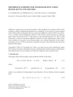
vector . Figure 3 gives a contour plot of det(I + ρRZ
δ
)asa
function of x and y. Such plots for the special case of i.i.d
fading and high SNR can also be found in [4]. From the fig-
ures, the contours of equal pairwise error probably do not
show circular symmetry unless R has rank 1. This can also
be verified from (40). The lack of circular symmetry leads
to the notion of preferred directions. Under the norm con-
straint
|x|
2
+ |y|
2
= 1, the pairwise error probability is sig-
nificantly lower if the difference vector α
= (x, y)
T
points
in a particular direction, for example, along the unit vector
(
±1/
√
2, ±1/
√
2)
T
instead of (±1, 0)
T
or (0, ±1)
T
.
In the three-dimensional case, R can be any three-dimen-
sional toeplitz block toeplitz (TBT) matrix. As special cases,
consider the correlation m atrices
R
1
=
⎛
⎜
⎝
100
010
001
⎞
⎟
⎠
, R
2
=
⎛
⎜
⎝
110
110
001
⎞
⎟
⎠
, R
3
=
⎛
⎜
⎝
111
111
111
⎞
⎟
⎠
,
(41)
respectively. The matrix R
1
represents i.i.d fading, R
2
refers
to the case h
1
= h
2
and independent of h
3
,whereasR
3
refers
to the block fading scenario h
1
= h
2
= h
3
.Thecontoursof
equal pairwise error probability are given in Figure 4.
As in the two-dimensional case, when R is full rank the
locus is star-shaped; in the block fading case where R has
rank 1, the locus i s a sphere. As before, the higher the rank of
R, the smaller the value of
|x|, |y|,and|z| required to achieve
agivenPEPatagivenρ. From the figures, it is clear, that in
order to design good signal constellations, the signal points
should be arranged in space such that the difference vectors
avoid the “nonpreferred” directions.
3.4. Key observations
Beyond three dimensions, things become difficult to visual-
ize; the aim of this section is to make some key observations
which help us to design signal constellations for correlated
fading channels. For the sake of completeness, we begin by
proving that the matrix RZ has nonneg a tive eigenvalues.
Theorem 1. The matrices Y
= RZ and
Y E[(h α)(h
α)
∗
],whereR = E[hh
∗
], Z = diag(|α
1
|
2
, |α
2
|
2
, , |α
n
|
2
),
and α is the column vector (α
1
, α
2
, , α
n
)
T
∈ C
n
,havethe
same eigenvalues.
Proof. Consider an n
× n matrix A and an index set γ ⊆
{
1, 2, , n} with k, k ≤ n elements. The k × k submatrix
A(γ) that lies in the rows and columns of A indexed by γ
is called a k-by-k principal submatrix of A.Ak-by-k princi-
pal minor is the determinant of such a principal submatrix.
There are
n
k
different k-by-k principal minors of A, and the
sum of these is denoted by E
k
(A). The characteristic func-
tion p
A
(s) de t (sI −A)canbewrittenintermsofE
k
(A)
S. Mallik and R. Koetter 7
10
5
0
5
10
y
10 50 510
x
(a)
10
5
0
5
10
y
10 50 510
x
(b)
10
5
0
5
10
y
10 50 510
x
(c)
Figure 3: Three contours of the pairwise error probability expression in the two-dimensional case, ρ = 10, r
0
= 1. (a) r
1
= 0 i.i.d fading,
rank (R)
= 2. (b) r
1
= 0.8+ j0.4 correlated fading, rank (R) = 2. (c) r
1
= 1, correlated fading, rank (R) = 1.
10
5
0
5
10
y
10
5
0
5
10
z
10
5
0
5
10
x
10
5
0
5
10
y
10
5
0
5
10
z
10
5
0
5
10
x
10
5
0
5
10
y
10
5
0
5
10
z
10
5
0
5
10
x
Figure 4: Surface of constant pairwise error probability in 3D case for R =R
1
, R
2
, R
3
,respectively,ρ = 10 and P(c
(i)
→ c
( j)
) = 10
−3
.
as p
A
(s) = s
n
− E
1
(A)t
n−1
+ E
2
(A)t
n−2
−···±E
n
(A). Thus,
it is sufficient to show that Y and
Y have the same minors.
Let γ
={i
1
, i
2
, , i
k
},1≤ k ≤ n, be an index set. But,
det (Y(γ))
= (
k
l
=1
|α
i
l
|
2
)det(R(γ)) = de t (
Y(γ)) which im-
plies p
Y
(s) = p
Y
(s).
Corollary 1. The matrix Y = RZ has nonnegative eigenvalues.
Proof. The matr ix Y is not Hermitian. However, the matrix
Y
as defined in Theorem 1 is Hermitian and positive semidef-
inite as E[z
∗
Yz] = E[|
n
k=1
z
∗
k
α
k
h
k
|
2
] ≥ 0. The result now
follows from Theorem 1.
Definition 1. The diversity order of a signal constellation is
the minimum Hamming distance between the coordinate
vectors of any two distinct points in the signal constellation.
We will denote the diversity order of a constellation M by
the symbol L(M). Note that di versity order is a property of
the signal constellation and does not depend on the channel
model.
Definition 2. The -product distance between two signal
points x and y that differ in l components, denoted by
d
(l)
p
(x, y)
2
, is the product of the nonzero components of the
difference vector e
= x − y, that is,
d
(l)
p
(x, y)
2
=
x
i
=y
i
x
i
− y
i
2
. (42)
In the high SNR regime for the i.i.d Rayleigh fading chan-
nel, the diversity order and the product distance of a constel-
lation are important criteria for code design [14]. This is
well-known in literature. For the correlated Rayleigh fading
channel, the generalization is quite straightforward and in-
volves taking the channel correlation matrix R into account.
This requires a generalization of the concept of the product
distance. See [15] for similar calculations for the multiple
antenna space-time codes. The calculations for our OFDM-
like scheme on the doubly dispersive channel are similar in
spirit.
For i.i.d fading, in the plot of pairwise error probability
versus signal-to-noise ratio, the diversity order determines
the slope of the curve. In correlated fading, the rank r of the
matrix RZ plays similar role. Note that this quantity is al-
ways smaller than the diversity order of the constellation, as
rank(RZ)
≤ min{rank(R), rank(Z)}.
8 EURASIP Journal on Applied Signal Processing
The kth elementary symmetric function of n numbers
t
1
, t
2
, , t
n
, k ≤ n,is
S
k
t
1
, t
2
, , t
n
=
1≤i
1
<···<i
k
≤n
k
j=1
t
i
j
. (43)
The following elementary theorem helps to generalize the
notion of product distance.
Theorem 2. Let d
≥ 1 be the Hamming weight of the differ-
ence vector α
∈ C
n
.Letr be the rank of the correlation matrix
R.Letr
α
be the rank and let λ
1
≥ λ
2
≥···≥λ
r
α
>λ
r
α
+1
=
···=
λ
n
= 0 be the eigenvalues of the mat rix RZ
α
.Then,
det
I + ρRZ
α
=
1+
r
α
k=1
ρ
k
S
k
λ
1
, λ
2
, , λ
n
, (44)
where 1
≤ r
α
≤ min{d, r}.
Proof. The proof is straightforward. The eigenvalues are
numbered in descending order. Hence, λ
r
α
+1
= 0implies
S
k
(λ
1
, , λ
n
) = 0forallk>r
α
.Thus,
det
I + ρRZ
α
=
n
i=1
1+ρλ
i
=
1+
n
k=1
ρ
k
S
k
λ
1
, λ
2
, , λ
n
=
1+
r
α
k=1
ρ
k
S
k
λ
1
, λ
2
, , λ
n
.
(45)
The rank of the product of two square matrices can be no
greater than the minimum of the ranks of the individual ma-
trices. Since rank(Z
α
) = d,wehaver
α
≤ min{d, r}.
It follows from the previous theorem that, for correlated
fading, in the high SNR regime
P
c
(i)
−→ c
( j)
≤
1
1+
r
α
k=1
ρ
k
S
k
λ
1
, λ
2
, , λ
n
≈
ρ
−r
α
S
r
α
λ
1
, λ
2
, , λ
n
for large ρ.
(46)
The quantity S
r
α
(λ
1
, , λ
n
), where α x − y, is the gener-
alization of the notion of product distance between x and y.
Unlike product distance, it depends on the channel statistics
since the eigenvalues and the quantity r
α
are functions of the
correlation matrix R. In i.i.d fading, we have R
= I
n×n
,which
implies r
α
= d. Further, |α
i
|
2
, i = 1, , n, are the eigen-
values of the diagonal matrix RZ
α
.ThusS
r
α
(λ
1
, , λ
n
) =
α
i
=0
|α
i
|
2
= d
P
(x, y).
3.5. Implications for code design for OFDM schemes
under the block fading assumption
Consider a signal constellation M in
C
n
with diversity order
L to be used for communication over the canonical channel
given by (19). Recall that the diversity order is an intrinsic
property of the signal constellation and does not depend on
the channel model. Given a particular channel, we say that
M achieves a diversity of m if for every pair of signal points
in M the pairwise error probability decays at least as fast as
ρ
−m
. A channel is specified by R, the correlation matrix of
the fading coefficients. This matrix depends on the channel
scattering function C
H
(ν, τ) and the grid parameters T and F
of the OFDM-like modulation scheme.
Let γ(M) be defined as the minimum of the rank of the
matrix RZ
α
over all choices of the difference vector α.Hence,
for a signal constellation M of diversity order L to achieve
adiversityofm on a channel with correlation matrix R,we
need
(i) m
≤ γ(M) ≤ min{rank (R), L},
(ii) for high signal-to-noise ratios, the pairwise error prob-
ability is smallest for the constellation with greatest
γ(M). For two constellations with the same γ(M), the
onewithgreaterS
γ
(λ
1
, λ
2
, , λ
n
) has a smaller pair-
wise error probability.
Untilnow,wehaveallowedarbitrarycorrelationbe-
tween the time-frequency channel coefficients in (19). The
level of time-frequency diversity is captured in the num-
ber of nonzero eigenvalues of the channel corr elation matrix
R
= E[hh
∗
]. As shown in [3], the level of delay-Doppler di-
versity can be estimated via the delay and Doppler spreads
and signaling duration of the signaling scheme. The max-
imum available delay-Doppler diversity, that is, the num-
ber of nonzero channel eigenvalues, can be accurately esti-
mated as D
=T
m
WB
d
T
s
,whereT
m
and B
d
are the de-
lay and Doppler spreads of the channel, and T
s
= NT and
W
= MF are the signaling duration and bandwidth, re-
spectively. This delay-Doppler diversity leads to the notion of
time-frequency coherence subspaces as argued in [3], result-
ing in a block fading interpretation of the doubly dispersive
channel in the short-time Fourier domain. In other words,
the number of signal space dimensions NM,canbepar-
titioned into D coherence subspaces, each with dimension
NM/D. In the block fading approximation, the channel coef-
ficients are assumed identical in each time-frequency coher-
ence subspace, whereas the coefficients in different subspaces
are statistically independent. The number of independent co-
herence subspaces, D, which also equals the delay-Doppler
diversity in the channel, then represents the maximum num-
ber of nonzero eigenvalues of the channel corr elation matrix
R. This means that the matrix R is a block-diagonal matrix
with D blocks.
In the next section, we use constellation partitioning
ideas to design codes with any desired diversity order and
then use the block fading interpretation to adapt the codes
to the channel structure.
So far we have been exclusively concerned with the pair-
wise e rror p robability P(c
(i)
→ c
( j)
). Using the union bound,
the probability of decoding error when c
(i)
is transmitted
P(error
| c
(i)
) is upper bounded as
P
error | c
(i)
≤
c
(j)
∈M, c
(j)
=c
(i)
P
c
(i)
−→ c
( j)
. (47)
S. Mallik and R. Koetter 9
Let M denote the number of signal points in constellation M .
Assuming all codewords have the same a priori probability,
that is, P(c
(i)
) = 1/M for all i,
P(error)
=
M
i=1
P
error | c
(i)
P
c
(i)
≤
1
M
M
i=1
M
j=1, j=i
P
c
(i)
−→ c
( j)
.
(48)
The above analysis is based on the pairwise error probability
and yields a good approximation to the overall probability of
error if the union bound is tight. This approach has its lim-
itations, in particular in the desig n of capacity approaching
schemes.
4. CODE DESIGN BY SET PARTITIONING
In 1977, Imai and Hirakawa [16] presented their multilevel
method for constructing binary block codes. Codewords
from the component codes, also called as outer codes, form
rows of a binary array, and the columns of this array are
used as information symbols for another code called the in-
ner code. If on the other hand, each column of this array of
outer codes is used to label a signal point in a signal con-
stellation, we obtain a coded-modulation scheme. Such tech-
niques were also used in [7, 17] for the design of effective
coded-modulation schemes for the AWGN channel. Nowa-
days, multilevel techniques, also called generalized concate-
nation, are well recognized as a powerful tool for designing
new codes in Hamming and Euclidean spaces [18]. In this
section we use the technique of generalized concatenation to
design signal constellations with high diversity order.
4.1. An example in two dimensions
Our idea to partition sig nal constellations is inspired by
Ungerboeck’s trellis coded-modulation schemes. Recogniz-
ing that the Euclidean distance is an important design pa-
rameter for minimizing pairwise error probability, in [7]
standard QAM constellations were partitioned such that sub-
constellations had greater Euclidean distance. For fading
channels, we design partitioning schemes to ensure that sub-
constellations have a greater diversity order. We illustrate this
by means of an example. We will generalize this scheme in
Section 4.3.
Consider the signal constellation M
1
shown in Figure 5.
It can b e defined as
M
1
x
1
, x
2
T
| x
i
∈
±
1
2
,
±
3
2
. (49)
We partition it into four subconstellations M
2
0
, M
2
α
, M
2
1
,and
M
2
α
as shown in Figure 5. The primary objective of the par-
titioning scheme is to ensure that the subsets M
2
i
have a
larger diversity order L than the parent constellation M
1
.
For this particular partitioning scheme, we have L(M
2
i
) =
2L(M
1
) = 2.
3/2
1/2
1/2
3/2
3/2 1/21/23/2
M
2
0
M
2
α
M
2
1
M
2
α
Figure 5: Algebraic description of partitioning scheme A.
4.2. Algebraic description of partitioning scheme A
To generalize scheme A to m dimensions we first need to give
it an algebraic description. This is done as follows. Let
F
4
denote the finite field of cardinality 4. Let α be a primitive
element of
F
4
. Let the elements of F
4
be given by {0, 1, α, α},
where
α denotes the element α
2
. Consider the bijective map
φ
α
: F
4
→{−3/2, −1/2, 1/2, 3/2} given by
φ
α
(γ) =
⎧
⎪
⎪
⎨
⎪
⎪
⎩
−
3
2
if γ
= 0,
i
−
3
2
if γ
= α
i
,1≤ i ≤ 3.
(50)
Let Φ
α
be the vector map corresponding to component-wise
scalar maps φ
α
.GivenasetS,letΦ
α
(S) denote the set of all
values the map Φ
α
can take as its argument varies over S.
As shown in Figure 5, the partitions are now identi-
fied by labels over
F
4
. The partition M
2
α
consists of the
four points (3/2,
−3/2), (1/2, −1/2), (−1/2, 1/2), (−3/2, 3/2)
in
R
2
. We say that this partitioning scheme is defined by its
generator matrix P
A
= (
11
1 α
), since the partitions M
2
0
, M
2
1
,
M
2
α
,andM
2
α
can then be defined as
M
2
0
= Φ
α
(γ,0)P
A
| γ ∈ F
4
,
M
2
1
= Φ
α
(γ,1)P
A
| γ ∈ F
4
,
M
2
α
= Φ
α
(γ, α)P
A
| γ ∈ F
4
,
M
2
α
= Φ
α
(γ, α)P
A
| γ ∈ F
4
.
(51)
It is easy to see that each of these partitions has diversity order
2. This is because, if s
1
, s
2
∈ M
2
i
and s
1
= s
2
, then s
1
−
s
2
is a multiple of Φ
α
((1, 1)). Thus s
1
and s
2
differ in two
coordinates.
We now use the idea of generalized concatenation to
combine the constellation M
1
in R
2
with suitably cho-
sen outer codes of length n to construct constellations in
R
2n
with desired diversity order. Consider two outer codes
C
i
[n, k
i
, d
i
]
4
, i = 1, 2, over F
4
of length n, dimension k
i
,and
minimum distance d
i
where d
1
>d
2
.CodeC
i
contains M
i
=
4
k
i
codewords. Each point in M
1
can be uniquely determined
by the label (ω
1
, ω
2
), where ω
1
, ω
2
∈ F
4
. In particular, the
10 EURASIP Journal on Applied Signal Processing
pair (c
1
k
, c
2
k
) of the kth coordinate, 1 ≤ k ≤ n, of the two code-
words c
1
= ( c
1
1
, c
1
2
, , c
1
n
) ∈ C
1
and c
2
= (c
2
1
, c
2
2
, , c
2
n
) ∈ C
2
can be used to label signal points in m
1
.Thus,apairofcode-
words, one from each outer code, labels a signal point in
R
2n
.
We thus have a construction for a signal constellation M
CM
in 2n-dimensional real space.
We now show that M
CM
has M
1
M
2
signal points and a
diversity order of at least min
i
{d
i
L(M
i
)},whereM
i
stands
for any one of the four subconstellations M
i
ω
, ω ∈ F
4
.Note
that L(M
i
) is well defined since al l of these subconstella-
tions have the same diversity order of 2. Fixing a codeword
c
1
∈ C
1
, M
2
different signal points can be labeled with code-
words of C
2
. Thus the cardinality of M
CM
is M
1
M
2
.Asig-
nal point s in M
CM
is uniquely identified by a pair of code-
words, one each from C
1
and C
2
. Consider two distinct sig-
nal points s
1
and s
2
in M
CM
. Since s
1
= s
2
we have two pos-
sibilities.
(1) The signal points correspond to distinct codewords
from C
1
. Since C
1
has a Hamming distance d
1
,itfol-
lows that s
1
and s
2
differ in at least d
1
times L(M
1
)
coordinates. Note that this holds true independent of
whether the two signal points correspond to the same
or different codewords from C
2
.
(2) The signal points correspond to the same codeword
from C
1
but different codewords from C
2
.Hence,ar-
guing as above, since two codewords from C
2
differ in
at least d
2
positions, s
1
and s
2
differ in at least d
2
times
L(M
2
) coordinates.
We conclude this subsection with some terminology that
will be helpful in subsequent sections. We partition the con-
stellation M
1
once to create four constellations at level 1,
viz., M
2
ω
, ω ∈ F
4
. We partition a second time to create 16
constellations at level 2,viz.,M
3
ω
1
,ω
2
, ω
1
, ω
2
∈ F
4
. The parti-
tioning is stopped when each constellation consists of a sin-
gle point. In order words, the parent constellation is at level
0 and the constellations at the last level consist of a single
point each. The order of a partitioning scheme is defined as
the number of levels in the scheme. This should not be con-
fused with the term diversity order. In subsequent sections,
the term M
1
will refer to any signal constellation that we
wish to part ition. It will not refer to the particular constel-
lation given by (49)unlessitisexplicitlymentionedtobe
so.
4.3. Generalizing partitioning scheme A
Scheme A described in the previous subsection has order 2.
In general an L
× m partition generator matrix P whose en-
tries are elements in
F
q
represents a scheme of order L in
m-dimensional real space with less than or equal to q signal
points per dimension.
Let α be a primitive element in
F
q
, the finite field with
q elements. Consider the map φ
α
: F
q
→{(−q +1)/2,
(
−q +3)/2, ,(q − 1)/2} given by φ
α
(γ) = i −(q − 1)/2, if
γ
= α
i
,1 ≤ i ≤ q − 1, and φ(0) = (−q +1)/2. Let Φ
α
be
the vector map corresponding to component-wise scalar
maps φ
α
.LetM
1
be a constellation carved out from the
integer lattice
Z
m
. Consider the partitioning matrix
P
⎛
⎜
⎜
⎜
⎜
⎜
⎜
⎜
⎜
⎜
⎝
11 1 ··· 1
1 αα
2
··· α
m−1
1 α
2
α
4
··· α
2(m−1)
.
.
.
.
.
.
.
.
.
.
.
.
.
.
.
1 α
L−1
α
2(L−1)
··· α
(L−1)(m−1)
⎞
⎟
⎟
⎟
⎟
⎟
⎟
⎟
⎟
⎟
⎠
, (52)
where L
≤ q −1, m ≤ q − 1, and the set
M
k+1
ω
1
,ω
2
, ,ω
k
Φ
α
βP | β =
β
L−k
, , β
1
, ω
k
, ω
k−1
, , ω
1
∈ F
L
q
.
(53)
In the above equation the vector β takes all possible val-
ues in
F
L−k
q
. Constellation M
k+1
ω
1
,ω
2
, ,ω
k
consists of q
L−k
points
each labeled by a distinct vector β. Further, it will be clear
from Theorem 3 that we need L
≤ m for the diversity or-
der of the constellation at level l to be a strictly increasing
function of l. We take a moment to clarify the notation. In
the above equation, α is a primitive element in
F
q
,whereas
ω
j
s represent arbitrary (not necessarily primitive) elements
F
q
. We thus have a partitioning scheme of order L in an m-
dimensional Euclidean space indexed by labels ω
k
∈ F
q
given
by
M
1
=
ω
1
M
2
ω
1
,
M
2
ω
1
=
ω
2
M
3
ω
1
,ω
2
,
.
.
.
M
L
ω
1
,ω
2
, ,ω
L−1
=
ω
L
M
L+1
ω
1
,ω
2
, ,ω
L−1
ω
L
.
(54)
The parameter ω
1
∈ F
q
labels the subconstellation M
1
ω
1
of
M
1
, ω
2
labels the subconstellation M
3
ω
1
,ω
2
of M
2
ω
1
, and so on.
Note that M
L
ω
1
,ω
2
, ,ω
L−1
consists of a set of q points given by
M
L+1
ω
1
,ω
2
, ,ω
L
, ω
L
∈ F
q
, For the example g iven in Section 4.1,
we have
M
1
= M
2
0
∪ M
2
α
∪ M
2
α
∪ M
2
1
,
M
2
ω
= M
3
ω0
∪ M
3
ωα
∪ M
3
ω
α
∪ M
3
ω1
∀ω ∈ F
4
.
(55)
Theorem 3. L(M
l
ω
1
,ω
2
, ,ω
l−1
) = (l +m−L)
+
,foralll such that
1
≤ l ≤ L,wherex
+
max{x,0}.
Proof. Consider that the two distinct points, that is, s
1
, s
2
∈
M
l
ω
1
,ω
2
, ,ω
l−1
, s
1
= s
2
, have the following identification labels:
(
β
L−l+1
···β
1
ω
l−1
··· ω
1
)and(
γ
L−l+1
···γ
1
ω
l−1
···ω
1
),
respectively. Further assume that s
1
, s
2
are chosen such that
β
1
= γ
1
.Letζ
k
β
k
− γ
k
, k = 1, , L − l + 1. Consider the
polynomial g(x)
= ζ
L−l+1
+ ζ
L−l
x + ···+ ζ
1
x
L−l
. Since ζ
1
= 0,
g(x) i s a polynomial of degree of L
− l and can have at most
L
− l roots in F
q
.But
s
1
− s
2
= Φ
α
g(1), g(α), g
α
2
, , g
α
m−1
,
(56)
S. Mallik and R. Koetter 11
where α is a primitive element in F
4
. This implies that signal
points s
1
and s
2
differ in at least m − (L − l) positions which
implies
L
M
l
ω
1
,ω
2
, ,ω
l−1
≥
(l + m − L)
+
. (57)
We now show that we have equality in (57). Consider the
polynomial h(x)
= (x − 1)(x − α) ···(x − α
L−l−1
). Let s
1
denote the signal point M
L+1
0,0, ,0
.
g
1
(x) =
L
i
ω
i
x
i−1
and let g
2
(x) = g
1
(x)+h(x). Let g
2
(x)
be of the form
L
i
ω
i
x
i−1
.Lets
2
be a point with identification
label (γ
L
, , γ
2
, γ
1
). It follows that the difference vector s
1
−
s
2
= Φ
ω
(
(h(1) h(ω) h(ω
2
) ··· h(ω
m−1
)
) has Hamming
weight (m
− L + l)
+
. Since the polynomial h( x)hasdegree
L
− l,wehaveγ
i
= ω
i
for 1 ≤ i ≤ l − 1, which implies
s
2
∈ M
l
ω
1
,ω
2
, ,ω
l−1
.
Theorem 3 shows that the diversity order increases as we
go down the part ition chain. It will be strictly increasing if
L
≤ m. The reason for this partitioning will be clear from
Theorem 4 where we will combine this partitioning scheme
with outer codes to create a signal constellation in higher di-
mensions with higher diversity. Figure 6 shows the partition-
ing scheme A in three dimensions. The constellation M
1
is
carved from a shifted version of
Z
3
, the integer lattice in three
dimensions, and has q
= 4 points per dimension. The parti-
tion scheme of order 3 can be represented by (53)and(54)
with L
= 3, m = 3, q = 4. Figure 6(a) shows the partition
M
2
0
which is further divided into 4 subpartitions M
3
00
, M
3
01
,
M
3
0α
,andM
3
0
α
, as shown in Figure 6(b).Asexpected,M
2
0
has
diversity 2 and M
3
0α
has diversity order 3. Figure 7 illustrates
this three-dimensional example in more detail.
4.4. Outer codes
In the example considered in Section 4.1, we needed two
outer codes. In general, we need L outer codes, where L is the
depth of the partitioning scheme. There are three parameters
that have to be chosen for each outer code C
i
[N, k
i
, d
i
]
p
i
.
(1) The finite field over which the outer code is defined.
This is dependent on the partitioning scheme. Con-
sider a partitioning scheme of order k.Lett
j
denote the
number of partitions at level j and
F
p
j
denote the finite
field over which the jth outer code is defined. To la-
beleachofthet
j
partitions M
j
1
, , M
j
t
j
, it is necessary
that p
j
≥ t
j
. For the particular partitioning scheme de-
scribed in the previous subsection, t
j
equals q,hence
p
j
≥ q suffices. We choose p
j
= q for all j.
(2) The block length N of the outer code. This is de-
pendent on a number of factors like design con-
straints and decoding complexity. If ergodic capacity-
achieving schemes are desired, it is necessary to con-
sider long block lengths.
(3) The rate R
i
of the outer codes. This is related to the de-
sired error performance. If pairwise error probability is
the cr iterion we wish to optimize, then the outer codes
are chosen such that each subpartition has the same
pairwise error probability. This will be elaborated in
Section 5.
We now describe the multilevel encoder and the multi-
stage decoding (MSD) algorithm, first presented by Imai and
Hirakawa in [16]. Figure 8 shows a multilevel encoder for a
partitioning scheme of order L. This figure appears in [18].
For simplicity, assume that p
1
= p
2
=···=p
L
= p, that
is, all outer codes are defined on the same field
F
p
. In the
encoder, a block of K source data symbols q
= (q
1
, , q
K
),
q
i
∈ F
p
, is partitioned into L blocks
q
i
=
q
i
1
, , q
i
k
i
, i = 1, , L, (58)
of length k
i
with
L
i
=1
k
i
= K.Eachdatablockq
i
is fed
into an individual p-ary encoder E
i
generating codewords
c
i
= (c
i
1
, , c
i
N
) of the component code C
i
. For simplic-
ity, we assume here equal code lengths N at all levels, but
the choice of code lengths can be arbitrary. For example,
block codes, convolutional codes, or turbo codes can be used.
The codeword symbols c
i
t
, t = 1, , N, of the codewords
c
i
, i = 1, , L, at one time instant t form the p-ary label
c
t
= ( c
1
t
, , c
L
t
), which is mapped to the signal point s
c
t
.
Let M
CM
be the constellation in R
mn
obtained by con-
catenating the partition scheme of order L as given by (53)
and (54)withL outer codes C
i
[N, k
i
, d
i
]
q
,1 ≤ i ≤ L.
Theorem 4 proves that M
CM
has cardinality
i
q
k
i
.Letη
denote the spectral efficiency in bits per real dimension of
M
CM
. It follows that
η
=
log
2
i
q
k
i
nm
=
log
2
q
m
R
i
, (59)
where R
i
is the rate of the ith outer code.
Theorem 4. The set M
CM
has cardinality
i
q
k
i
and diversity
order of at least min
l
{d
l
(l + m −L)
+
},wherex
+
max{x,0}.
Proof. Let c
(i)
be a codeword in the outer code C
i
[N, k
i
, d
i
]
q
,
1
≤ i ≤ L. Further, let (c
i
1
, c
i
2
, , c
i
N
) be the representation of
the codeword c
i
.TheL × N codeword m atrix
⎛
⎜
⎜
⎜
⎜
⎜
⎜
⎜
⎜
⎝
c
1
1
c
1
2
··· c
1
N
c
2
1
c
2
2
··· c
2
N
.
.
.
.
.
.
.
.
.
.
.
.
c
L
1
c
L
2
··· c
L
N
⎞
⎟
⎟
⎟
⎟
⎟
⎟
⎟
⎟
⎠
(60)
uniquely identifies a signal point, say s,inM
CM
. Since there
are
i
q
k
i
such distinct matrices, it implies that M
CM
has
cardinality
i
q
k
i
.Theith column of (60) identifies a signal
point s
i
in M
1
. Similarly, let t ∈ m
CM
be the point corre-
sponding to codewords d
(i)
,1≤ i ≤ L. Let the quantity l be
defined as l
= min{k | c
(k)
= d
(k)
}. This implies that c
(l)
and
d
(l)
differ in at least d
l
positions. Let i be one such position
and let ω
j
= c
( j)
i
. This implies that s
i
, t
i
∈ M
l
ω
1
,ω
2
,ω
l−1
and
there exists no γ
∈ F
q
such that s
i
, t
i
∈ M
l+1
ω
1
,ω
2
,ω
l−1
,γ
.Thisim-
plies that s
i
and t
i
differ in (m −L + l)
+
positions. This is true
for at least d
l
such positions in the outer code. This implies
that s and t differ in at least d
l
(m−L+l)
+
positions. The claim
now follows by taking a minimum over l
= 1, 2, , L.
12 EURASIP Journal on Applied Signal Processing
M
2
0
z
y
x
(a)
M
3
00
M
3
01
M
3
0α
M
3
0
α
z
y
x
(b)
Figure 6: Partitioning scheme A in three dimensions q = 4, m = 3, L = 3. (a) Partition M
2
0
. (b) Subpartitions M
3
00
, M
3
01
, M
3
0α
, M
3
0
α
.
Note that (l + m − L)
+
is the diversity order of a subcon-
stellation M
l
ω
1
,ω
2
, ,ω
l−1
at level l. This is an increasing func-
tion of l. Since the diversity order of M
CM
is the minimum
over l of the product d
l
L(M
l
), the distance d
l
of outer code
C
l
, needed to attain a particular value of M
CM
,decreases
as l increases. This enables higher rate codes to be used at
higher levels, that is, levels corresponding to a larger value of
l. Theorem 4 also illustrates how by lowering the minimum
distance d
i
of all the outer codes, thereby increasing their rate,
we can trade off the diversity order of the constellation M
CM
for the rate of the code. The significance of Theorem 3 also
now becomes clear. In particular if the fading is i.i.d, then
the outer code C
l
sees an equivalent channel with diversity
(l + m
− L)
+
. The notion of equivalent channels is described
in detail in [18]. Since this is a better channel than the chan-
nel seen by the outer code C
l−1
, C
l
needs a lower correction
capability than C
l−1
. If the fading is not i.i.d but correlated,
C
l
may not see a channel with diversity as high as (l+m−L)
+
,
but the channel will be better than that seen by C
l−1
.
We now take a look at the decoding algorithm for multi-
level codes. Figure 9 shows a multistage decoder. This figure
also appears in [18]. In this low-complexity decoding algo-
rithm, the component codes C
i
are successively decoded by
the corresponding decoders D
i
. At stage i,decoderD
i
pro-
cesses not only the block y
= (y
1
, , y
N
), y
k
∈ R
m
,where
m is the dimension of the signal space, but also decisions
c
j
,
j
= 1, , i − 1, of the previous decoding stages j.LetP
e, j
denote the word error rate of code C
j
given that the previous
j
− 1 stages have been decoded correctly, that is,
P
e, j
P
c
j
= c
j
| c
1
= c
1
, , c
j−1
= c
j−1
. (61)
It follows from the union bound that the overall probability
of error P
e
is upper bounded by
P
e
≤
L
j=1
P
e, j
. (62)
Let R
=
R
i
denote the sum of the rates of the outer
codes. As mentioned in [18], if error propagation in MSD
is neglected, the bit-error P
b
probability for multilevel coded
transmissions is given by
P
b
=
L
l=1
R
i
R
P
b,i
, (63)
where P
b,i
denotes the bit-error probability for decoding at
level i when error-free decisions are assumed at the decoding
stages of the previous levels.
4.5. Adaptation of the partitioning scheme to the block
fading channel
So far, we have seen how the partitioning scheme can be used
with outer codes to construct codes of any desired diversity
order. We now adapt these codes to a block fading channel.
Consider a coding scheme over M tones and N time slots.
The underlying channel structure results in a block fading
channel with D coherent subspaces or blocks each of size
b
= NM/D. To design a coded-modulation scheme with
spectral efficiency of η bits per dimension, start with an in-
teger lattice in m
≤ D dimensions, and carve out a constel-
lation M
1
consisting of q
m
points. The parameter m is cho-
sen to be quite smaller than D. This is explained in detail in
Section 5.1. This signal constellation has an uncoded spec-
tral efficiency of log
2
q bits per dimension. The parameter q
is chosen so as to ensure a constellation expansion factor of at
S. Mallik and R. Koetter 13
M
2
0
M
3
00
M
3
01
M
3
0α
M
3
0
α
z
y
x
(a)
M
2
α
M
3
α0
M
3
α1
M
3
αα
M
3
α
α
z
y
x
(b)
M
2
α
M
3
α0
M
3
α1
M
3
αα
M
3
αα
z
y
x
(c)
M
2
1
M
3
10
M
3
11
M
3
1α
M
3
1
α
z
y
x
(d)
Figure 7: Partitioning scheme A in three dimensions q = 4, m = 3, l = 3. M
1
decomposes into three partitions M
2
0
, M
2
α
, M
2
α
,andM
2
1
.(a)
Partition M
2
0
and its subpartitions M
3
00
, M
3
01
, M
3
0α
, M
3
0
α
. (b) Partition M
2
α
and its subpartitions M
3
α0
, M
3
α1
, M
3
αα
, M
3
α
α
. (c) Partition M
2
α
and
its subpart itions M
3
α0
, M
3
α1
, M
3
αα
, M
3
αα
. (d) Partition M
2
1
and its subpartitions M
3
10
, M
3
11
, M
3
1α
, M
3
1
α
.
q
Partitioning
of data
q
L
.
.
.
q
1
Encoder E
L
.
.
.
Encoder E
1
c
L
.
.
.
c
1
Mapper/
modulator
s
Figure 8: Multilevel encoder.
14 EURASIP Journal on Applied Signal Processing
y
Decoder D
1
c
1
Decoder D
2
c
2
.
.
.
Decoder D
L
c
L
Figure 9: Multistage decoding (MSD) algorithm.
8timeslots
1
c
1
1
, c
2
1
5
c
1
3
, c
2
3
9
c
1
1
, c
2
1
13
c
1
3
, c
2
3
2
c
1
5
, c
2
5
6
c
1
7
, c
2
7
10
c
1
5
, c
2
5
14
c
1
7
, c
2
7
3
c
1
9
, c
2
9
7
c
1
11
, c
2
11
11
c
1
9
, c
2
9
15
c
1
11
, c
2
11
4
c
1
13
, c
2
13
8
c
1
15
, c
2
15
12
c
1
13
, c
2
13
16
c
1
15
, c
2
15
17
c
1
2
, c
2
2
21
c
1
4
, c
2
4
25
c
1
2
, c
2
2
29
c
1
4
, c
2
4
18
c
1
6
, c
2
6
22
c
1
8
, c
2
8
26
c
1
6
, c
2
6
30
c
1
8
, c
2
8
19
c
1
10
, c
2
10
23
c
1
12
, c
2
12
27
c
1
10
, c
2
10
31
c
1
12
, c
2
12
20
c
1
14
, c
2
14
24
c
1
16
, c
2
16
28
c
1
14
, c
2
14
32
c
1
16
, c
2
16
4tones
Figure 10: Interleaved channel.
least 2, that is, log
2
q/η≥2. Fixing q constrains how large
m can be as m
≤ q−1. Now par tition M
1
L times thereby as-
signing each signal point a q-ary label of length L.UseL outer
codes over
F
q
. In our partitioning scheme, we fix L = m, that
is, we par tition m times and hence need to choose m outer
codes. The rates R
i
of the outer codes should be chosen to
satisfy the desired spectral efficiency as per (59). Finally the
coded bits of the outer codes are passed through an inter-
leaver before being modulated and transmitted. We choose
short constraint length convolutional codes as outer codes.
The interleaver is designed so that successive code symbols
of each outer code see independent fades [19].
Consider the following example of how the interleaver
is designed. It also helps to explain how the coded sy m-
bols are mapped onto the different time frequency slots in
OFDM modulation. Consider a channel with M
= 4tones.
Let the coherence time correspond to 4 time slots as shown
in Figure 10. Let the tone-spacing be such that the coherence
bandwidth of the channel corresponds to 2 tones. A block
of 8 time-frequency slots corresponds to a time-frequency
coherence subspace and is indicated in the figure by a par-
ticular shade of the grey color. All time-frequency slots in a
coherence subspace see the same fade. Each time-frequency
slot corresponds to one complex dimension or equivalently
2 real dimensions. We code jointly over 8 time slots and 4
tones, which corresponds to 2 sets of 32 real dimensions cor-
responding to the inphase and quadrature components. Thus
we are coding across D
= 4 coherence subspaces each of size
b
= 8. The desired spectral efficiency η is 1 bit per real di-
mension.
We cho os e M
1
as defined by (49) as the signal constella-
tion with 16 points. This fixes m
= 2 and hence we partition
twice and need two outer codes over
F
4
. We choose convolu-
tionalcodesasoutercodes.Thusweneedaratepair(R
1
, R
2
)
such that R
1
+R
2
= 1. Let c
1
and c
2
be codewords correspond-
ing to outer codes C
1
and C
2
, respectively. We first modulate
over the inphase components and then over the quadrature
components. A pair of code symbols (c
1
t
, c
2
t
), 1 ≤ t ≤ 16,
uniquely identifies a signal s
t
= (s
t,1
, s
t,2
) ∈ R
2
.Thus(c
1
1
, c
2
1
)
determines signal point s
1
= (s
1,1
, s
1,2
) and we send s
1,1
in
over time-frequency slot 1 and s
1,2
over time-frequency slot
9 which is that first slot that fades independently of slot 1.
We indicate this in Figure 10 by noting down in c
1
1
, c
2
1
in the
time-frequency slots numbered 1 and 9. Similarly, we send
s
2,1
and s
2,2
over time-frequency slots 17 and 25, respectively,
which fade independently of each other and slots 1 and 3.
We now have run out of independently fading slots, so the
next signal point corresponding to t
= 3 is sent over slots 5
and 13. We continue till t
= 16 at which point the inphase
components of the 32 time-frequency slots have been ex-
hausted. We then modulate for the quadrature components.
Thus the primary objective of interleaving the code symbols
is to guarantee that successive code symbols see independent
fades. This helps to combat slow or block fading by creating
an implicit time-frequency diversity effect. This trick is well
known, see, for example [19]. We fixed M
= 4andN = 8,
but the procedure to interleave for larger values of M and N
is a natural extension of the above technique. Let α be the
difference vector between two signal points in M
CM
.LetE
n
denote the square matrix of all ones of size n.LetI
n
denote
an identity matrix of size n. In the uninterleaved block fad-
ing channel with D blocks of length b each, the matrix R is
given by R
= E
b
⊗ I
D
. In the interleaved channel it is given
by R
= I
D
⊗E
b
,where⊗ denotes the tensor product between
two matrices. The amount of delay that can be tolerated in-
fluences the value of N and hence the number of coherence
subspaces D. In the subsequent sections, when we mention
interleaver we mean the interleaver designed above.
In Section 3.3 the notion of preferred directions was in-
troduced. A direction α is a preferred direction if the quantity
det(I + ρRZ)
= 1+
r
α
k=1
ρ
k
S
k
(λ
1
, λ
2
, λ
n
)islarge.Herer
α
denotes the rank of the matrix RZ
α
. Since the constellation
M
CM
is carved from an integer lattice it follows that if
S
k
λ
1
, λ
2
, , λ
n
> 0 =⇒ S
k
λ
1
, λ
2
, , λ
n
≥ 1, (64)
where any constant scaling factor corresponding to the de-
siredSNRhasbeenabsorbedinthequantityρ. Further,
choosing rates R
i
of the outer codes so as to maximize the
diversity order of the constellation M
CM
, and using an in-
terleaver as described above to ensure that consecutive code
symbols of the convolutional code see independent fades en-
sures the rank of the matrix RZ
α
is large. The codes that
we design do not maximize the quantity S
r
α
(λ
1
, λ
2
, , λ
n
).
However as mentioned above, for our codes, the quantity
S
r
α
(λ
1
, λ
2
, , λ
n
) is never less than 1. Thus for a block fading
channel, our choice of a constellation carved from an integer
lattice and the interleaver described above helps to approxi-
mate the problem of designing constellations with difference
S. Mallik and R. Koetter 15
1111
1010
0101
0000
1011
1110
0001
0100
0111
0010
1101
1000
0011
0110
1001
1100
Scheme A1
1010
1111
0101
0000
1110
1011
0001
0100
0110
0011
1001
1100
0010
0111
1101
1000
Scheme A2
Figure 11: Binary labels for partitioning scheme A.
vectors along preferred directions to the problem of parti-
tioning an integer lattice so as to ensure a high diversity or-
der.
5. SIMULATION RESULTS
Consider a transmission scheme over M
= 16 tones. We
choose to code across 16 tones and N
= 128 time slots to
exploit the time-frequency diversity. The underlying time-
frequency coherence structure results in a block fading chan-
nel with say D
= 8 coherence subspaces each of size b = 256.
We also consider other scenarios, viz., D
= 16, b = 128,
and D
= 32, b = 64. In particular, larger the value of D,
the “richer” the channel and better is the error performance
of a given coding scheme. We desire a coding scheme with
spectral efficiency of η
= 1 bit per real dimension. We code
over the inphase and quadrature components separately. We
choose M
1
as the 16-point constellation over m = 2 dimen-
sionsasspecifiedasby(49). Since q
= 4, we need two outer
codes o ver
F
4
.
As mentioned earlier, we choose convolutional codes as
outercodes.Thisisprimarilybecausewewillusedecodeus-
ing the BCJR algorithm to minimize the symbol-(bit-) error
rate. For convolutional codes, the complexity of the code is
determined by a parameter ν called the total memory of the
encoder for the code. An encoder for a con volutional c ode,
by design, corresponds to a k-input, n-output finite state ma-
chine. A convolutional code is said to have total memory of
ν if 2
ν
represents the total number of states of the state ma-
chine.
Instead of working with outer codes over
F
4
we choose
to work with binary outer codes. As a result we have to map
the 4-ary labels of the signal points to binary labels. As il-
lustrated in Figure 11, there are two distinct ways of doing
this. At each partition level, the neighbors of signal points
in scheme A2 differ in fewer bit positions than those of sig-
nal points in A1. Hence for working with binary outer codes
we choose scheme A2. It is important to remark here that if
4-ary outer codes are used we do not need to make this dis-
tinction.
Let R
1
and R
2
denote the rates of the first and second
outer codes, respectively. Since the uncoded scheme has a
spectral efficiency of 2 bits per dimension, this means that we
10
1
10
2
10
3
10
4
10
5
Bit-error probability
56789101112
E
b
/N
0
(dB)
R
= 1/3OFDcode
R
= 2/3OFDcode
R
= 1/4OFDcode
R
= 3/4OFDcode
Figure 12: Performance of M
1
with the rate pairs (1/3, 2/3) and
(1/4, 3/4) using optimal free distance (OFD) convolutional codes
on a block fading channel of 32 blocks of size 64 each. η
= 1 bit/real
dimension. All codes have ν
= 5,excepttherate1/4 code which has
ν
= 4.
have to choose the rate pair (R
1
, R
2
) such that R
1
+ R
2
= 1.
We consider two such rate pairs: (1/3, 2/3) and (1/4, 3/4).
Figure 12 shows the performance of the rate pairs
(1/3, 2/3) and (1/4, 3/4) under multistage decoding. The
outer codes were decoded by the BCJR algorithm. The BCJR
algorithm was run on a window of size 2048 bits. The X
axis refers to the energy per bit for the combined modula-
tion scheme. Further, while calculating the bit-error prob-
ability for the second outer code, we assume that the first
code has been decoded correctly. The aim is to choose r ates of
the outer codes so that their individual bit-error rate (BER)
curves are m atched as closely as possible. In order words, we
choose the outer codes using the equal error probability rule
of [18].
As can be seen from Figure 12, for the rate pair (1/3, 2/3),
for a given trellis complexity of both outer codes, the perfor-
mance of the overall code is determined by the first outer
code. For the rate pair (1/4, 3/4), the BER curves are well
matched. The rate pair (1/4, 3/4) has a better performance
than the (1/3, 2/3) pair.
Figure 13 compares the performance of the same rate
pair (1/4, 3/4) on a block fading channel with D
= 32 and
b
= 64 with that on a block fading channel with D = 16 and
b
= 128. As before the rate 1/4codeandrate3/4haveto-
tal memory of 4 and 5, respectively. As expected the plots for
the channel with greater D have a steeper slope. T he “richer”
channel gains about 2 dB at a bit-error rate of 10
−4
.
5.1. Further guidelines on the adaptation of the
partitioning scheme and outer codes to
the block fading channel
In this section, we show how to adapt the parameter m and
the total memory of the convolutional outer codes to the
16 EURASIP Journal on Applied Signal Processing
10
1
10
2
10
3
10
4
10
5
Bit-error probability
56789101112
E
b
/N
0
(dB)
R
= 1/4 (16, 128)
R
= 3/4 (16, 128)
R
= 1/4 (32, 64)
R
= 3/4 (32, 64)
Figure 13: Performance improvement of M
1
with the rate pair
(1/4, 3/4) on the block fading channel with parameters D
= 32,
b
= 64 as compared to the block fading channel with parameters
D
= 16, b = 32. η = 1 bit/dim.
channel parameter D. The relationship between m and D is
best illustrated by means of an example. For a target spectral
efficiency of η
= 1 bit per real dimension, we consider two
schemes corresponding to choosing m
= 1 and 2, respec-
tively. If m
= 1, then we use 4 PAM as our signal constellation
in 1-dimensional space and combine it with a rate 1/2outer
code. Since m
= 1 we need only one outer code and there
is no partitioning involved. We compare the performance of
this scheme with a scheme corresponding to m
= 2, that is,
the constellation M
1
coupled with the rate pair (1/4, 3/4).
Note that both 4-PAM and M
1
have an uncoded spectral effi-
ciency of 2 bits per dimension. We simulate the performance
of these two competing schemes over 3 different block-fading
channels characterized by D
= 16, 32, and 2048, respectively,
with the product Db kept constant at 2048. We constrain the
total number of states in the encoder for each scheme to be
not greater than 64.
Figure 14 shows that for low values of D the 4-PAM
scheme beats the multilevel scheme. But as the diversity in
the channel, characterized by the parameter D, increases, the
multilevel scheme per forms better. The convolutional en-
coder for the multilevel scheme has 16 + 32
= 48 states. For
the channel with D
= 32, b = 64, it beats the 4-PAM with
a 32 state encoder by 1.5 dB at a BER of 10
−5
.Itperforms
as well as the 4-PAM with a 64 state encoder. As shown in
Figure 15, the performance gains are even higher on an i.i.d
channel, here the multilevel code gains over 1 dB at a BER of
10
−5
.
Let R
= I
D
⊗E
b
denote the channel correlation matrix of
the interleaved block fading channel. We use short constraint
length convolutional codes as outer codes. Let α denote the
difference between two signal points s
1
, s
2
∈ M
CM
cor-
responding to codewords (c
1
1
, c
2
1
, , c
L
1
)and(c
1
2
, c
2
2
, , c
L
2
),
respectively. We say that α is of type i,1
≤ i ≤ L, and if
c
j
1
= c
j
2
for all j such that 1 ≤ j<iand c
1
i
= c
2
i
.Ifα is of
type i then its Hamming weight cannot be less than L(M
i
)d
i
,
where d
i
is the free distance of convolutional outer code C
i
.
Suppose α is of type i. It follows that
rank(RZ
α
) ≤
min
D
m
, d
i
L(M
i
). (65)
The d
i
’s are a decreasing function of i,hencem should be
chosen such that
D/m is not smaller than d
L
.
For a given total memory, which is a measure of the com-
plexity of the encoder and decoder of the convolutional code,
and spectr al efficiency η, increasing m, the dimensionality
of the uncoded signal constellation M
1
increases the diver-
sity order of the coded superconstellation M
CM
provided the
L outer codes are chosen as OFD codes for the given total
memory
ν
i
= ν, I = 1, , L.However,ifthechannelis
poor, that is, D is low or equivalently the rank of channel
matrix R is low, the extra diversity order is of no use as in-
dicated above. As D increases, or equivalently, as the rank of
the matrix R increases, the extra diversity order gained by
partitioning in higher dimensions comes into play and there
is a corresponding-increase in performance as illustrated in
Figures 14 and 15.
6. CONCLUDING REMARKS
This paper dealt with a framework for communication
over doubly dispersive channels. Using the fact that Weyl-
Heisenberg bases approximately diagonalize an underspread
linear system we arrived at a canonical formulation of mod-
ulation and code design. We derived the code design crite-
ria and characterized the maximum achievable diversity in
terms of the scattering function of the channel. We then in-
troduced new set partitioning techniques for multilevel cod-
ing schemes for the canonical fading channel model. We
used these partitioning schemes to partition a signal constel-
lation M
1
in m dimensions and combined it with L outer
codes C
l
[N, k
l
, d
l
]
q
,1 ≤ l ≤ L, to design a coded signal
constellation M
CM
in nm dimensions. To a first-order ap-
proximation, the performance of this scheme is determined
by its diversity order L
∗
= min
l
d
l
(l + m − L)
+
.Thecon-
stellation M
CM
has
L
l
=1
q
k
l
points. This implies that it is
straightforward to trade constellation size for diversity or-
der by adjusting the rate of the outer codes. The algebraic
description through a generator matrix enables partitioning
in large dimensions. This ability to partition in arbitrarily
large dimensions and change to the rate of the outer codes
gives us the flexibility to adjust the scheme to the “rich-
ness” of the fading channel, that is, the number of non-
zero e igenvalues of R. In other words, if the channel offers
more diversity, then one can increase the rate of the outer
codes while maintaining the same error probability. We de-
scribed a procedure to adapt these codes to the block fad-
ing channel thereby making them suitable for coded mod-
ulation schemes over doubly dispersive channels. Finally we
illustrated the performance of these codes through simula-
tions.
S. Mallik and R. Koetter 17
10
1
10
2
10
3
10
4
10
5
Bit-error probability
56789101112
E
b
/N
0
(dB)
R = 1/4 ν = 5 (16, 128)
R
= 3/4 ν = 6 (16, 128)
4-PAM ν
= 6 (16, 128)
(a)
10
1
10
2
10
3
10
4
10
5
10
6
Bit-error probability
5678910111213
E
b
/N
0
(dB)
R = 1/4 ν = 4 (32, 64)
R
= 3/4 ν = 5 (32, 64)
4-PAM ν
= 5 (32, 64)
4-PAM ν
= 6 (32, 64)
(b)
Figure 14: Performance comparison of the 16-point constellation M
1
with rate pair (1/4, 3/4) versus 4-PAM with rate 1/2 outer code on
two different block fading channels. (a) D
= 16, b = 128, (b) D = 32, b = 64.
APPENDIX
We now derive an expression for the pairwise error probabil-
ity of the block-coded modulation scheme. Let c be a code-
word chosen with equal probability from a codebook C. C
can also be interpreted as a set of points in NM-dimensional
complex space
C
NM
.Lety be the received vector. Assum-
ing perfect channel state information at the receiver, the
maximum-likelihood decoder output
c is given by
c = argmax
c∈C
f
N
y − h
E
s
c
=
arg min
c
(i)
∈C
NM
−1
k=0
y
k
−
E
s
h
k
c
(i)
k
2
,
(A.1)
where f
N
(n) = (1/(2πσ
2
)
NM
)exp(−n
∗
n/2σ
2
) is the proba-
bility density function of the complex Gaussian vector n.Let
c
(i)
, c
( j)
be two codewords in C. The conditional probabil-
ity of mistaking c
(i)
for another codeword, say c
( j)
,isgiven
by
P
c
(i)
−→ c
( j)
| h
=
NM−1
k=0
y
k
−
E
s
h
k
c
(i)
k
2
≥
NM−1
k=0
y
k
−
E
s
h
k
c
( j)
k
2
=
P
NM−1
k=0
n
k
2
≥
NM−1
k=0
n
k
+
E
s
h
k
c
(i)
k
− c
( j)
k
2
.
(A.2)
Define
A
=
E
s
2
NM−1
k=0
h
k
2
c
( j)
k
− c
(i)
k
2
,
β
=
NM−1
k=0
Re
E
s
h
k
c
( j)
k
− c
(i)
k
n
∗
k
,
(A.3)
where A is a constant and β is a real-valued Gaussian random
variable with zero mean and variance 2Aσ
2
.Letα ∈ C
NM
be
the difference vector, that is, α
= c
(i)
− c
( j)
.LetZ
α
be an
NM
×NM diagonal matrix with kth diagonal entry given by
|α
k
|
2
. We drop the subscript α where there is no chance of
confusion. Equation (A.2)canberewrittenas
P
c
(i)
−→ c
( j)
| h) = P(β ≥ A) = Q
A
2σ
2
≤
e
−A/4σ
2
= e
−(E
s
/8σ
2
)h
∗
Zh
,
(A.4)
where Q(x)
= (1/
√
2π)
∞
x
e
−y
2
/2
dy and we have used the up-
per bound Q(x)
≤ (1/2)e
−x
2
/2
which is asymptotically tight.
Under the assumption that the matrix R has full rank,
the probability density function of h is well defined and is
given by f
H
(h) = (1/π
n
det(R)) exp(−h
∗
R
−1
h). Further for
simplicity, assume Z to be invertible. We will show shortly
that this assumption is not necessary. The pairwise error
probability averaged over the channel realizations is given
18 EURASIP Journal on Applied Signal Processing
10
1
10
2
10
3
10
4
10
5
Bit-error probability
567891011
E
b
/N
0
(dB)
R = 1/4 ν = 4 (2048, 1)
R
= 3/4 ν = 5 (2048, 1)
4-PAM ν
= 6 (2048, 1)
Figure 15: Perfor mance comparison of the 16-point constellation
M
1
with rate pair (1/4, 3/4) versus 4-PAM with rate 1/2 outer code
on the i.i.d channel, that is, D
= 2048, b =1.
by
P
c
(i)
−→ c
( j)
≤
e
−(E
s
/8σ
2
)h
∗
Zh
f
H
(h) dh (A.5)
=
det R
−1
(π)
NM
e
−h
∗
((E
s
/8σ
2
)Z+R
−1
)h
dh (A.6)
=
det(R
−1
)
det(R
−1
+(E
s
/8σ
2
)Z)
×
det
R
−1
+(E
s
/8σ
2
)Z
(π)
NM
e
−h
∗
(E
s
/8σ
2
)Z+R
−1
)h
dh
(A.7)
=
1
det
I +(E
s
/8σ
2
)RZ
. (A.8)
Since Z and R are positive definite, (R +(E
s
/8σ
2
)Z
−1
)
−1
is positive definite and hence a valid autocorrelation matrix.
As a result, the term in square brackets in (A.7) integrates out
to 1.
If R does not have full rank, the probability density func-
tion f
H
(h) is not defined. We show that even in this case the
upper bound on the pairwise error probability given by (A.8)
holds. Let x
= (x
1
, x
2
, , x
n
)
T
and v = (v
1
, v
2
, , v
n
)
T
be
random vectors defined on the probability space (Ω, F ,P ).
Define y
m
= x +(1/m)v.Thus,
lim
m→∞
y
m
= x almost surely. (A.9)
Let f :
C
n
→ R and suppose that there is a real number
M such that
|f (s)|≤M for all s ∈ C
n
. From the bounded
convergence theorem [20, Section 4.2], we have
E
y
m
f
y
m
−→ E
x
f (x)
, (A.10)
where E[
·] denotes the expectation operator.
If we define y
m
= h +(1/m)v where v is a zero-mean cir-
cularly symmetric complex Gaussian with E[vv
∗
] = I, then
y
m
is also zero-mean circularly sy mmetric complex Gaussian
with positive definite correlation matrix R
m
= E[y
m
y
∗
m
] =
R +(1/m
2
)I.ThusR
m
has full rank irrespective of the rank of
R and hence y
m
has a well-defined probability density func-
tion. Define f (x)
= e
(−E
s
/8σ
2
)h
∗
Z
x
h
≤ 1forallx ∈ C
NM
.It
follows from (A.4), (A.8), and (A.10) that
E
f
y
m
=
1
det
I +
E
s
/8σ
2
R +
1/m
2
I
Z
(A.11)
and hence
P
c
(i)
−→ c
( j)
≤
E
h
f (h)
=
lim
m→∞
E
f
y
m
=
1
det
I +
E
s
/8σ
2
RZ
.
(A.12)
Similarly, since the determinant of a matrix is a continuous
function of its entries, a limiting argument can be used to
show that (A.8) holds even if Z does not have full rank.
ACKNOWLEDGMENTS
The first author would like to thank Dr. Helmut Boelcskei
and Dr. Joseph Boutros for their help during various stages
of preparing this manuscript. We also would like to thank the
anonymous reviewers whose comments helped to improve
the quality of this manuscript. This work was supported in
part by the National Science Foundation under Grant NSF-
CCF 0325924 and a Vodafone-US Foundation Graduate Fel-
lowship. The material in this paper was presented in part at
the 2002 and 2004 International Symposium on Information
Theory (ISIT).
REFERENCES
[1] W. Kozek, Matched Weyl-Heisenberg expansions of nonstation-
ary environments, Ph.D. thesis, Vienna University of Technol-
ogy, Vienna, Austria, March 1997.
[2] W. Kozek, “Adaptation of Weyl-Heisenberg frames to under-
spread environments,” in Gabor Analysis and Algorithms: The-
ory and Applications,H.G.FeichtingerandT.Strohmer,Eds.,
pp. 323–352, Birkh
¨
auser, Boston, Mass, USA, 1998.
[3]K.Liu,T.Kadous,andA.M.Sayeed,“Orthogonaltime-
frequency signaling over doubly dispersive channels,” IEEE
Transactions on Information Theory, vol. 50, no. 11, pp. 2583–
2603, 2004.
[4] X. Giraud, E. Boutillon, and J. C. Belfiore, “Algebraic tools to
build modulation schemes for fading channels,” IEEE Transac-
tions on Information Theory, vol. 43, no. 3, pp. 938–952, 1997.
[5] J.BoutrosandE.Viterbo,“Signalspacediversity:apower-and
bandwidth-efficient diversity technique for the Rayleigh fad-
ing channel,” IEEE Transactions on Information Theory, vol. 44,
no. 4, pp. 1453–1467, 1998.
S. Mallik and R. Koetter 19
[6] G. Caire, G. Taricco, and E. Biglieri, “Bit-interleaved coded
modulation,” IEEE Transactions on Information Theory,
vol. 44, no. 3, pp. 927–946, 1998.
[7] G. Ungerboeck, “Channel coding with multile vel/phase sig-
nals,” IEEE Transactions on Information Theory, vol. 28, no. 1,
pp. 55–66, 1982.
[8] L. Zadeh, “Time-varying networks, I,” Proceedings of IRE,
vol. 49, pp. 1488–1503, 1961.
[9] J.G.Proakis,Digital Communications, chapter 14, McGraw-
Hill, New York, NY, USA, 4th edition, 2001.
[10] G. Matz and F. Hlawatsch, “Time-frequency transfer function
calculus of linear time-varying systems,” in Time-Frequency
Signal Analysis and Processing,B.Boashash,Ed.,Prentice-Hall,
Englewood Cliffs, NJ, USA, 2003.
[11] W. Kozek and A. F. Molisch, “Nonorthogonal pulseshapes for
multicarrier communications in doubly dispersive channels,”
IEEE Journal on Selected Areas in Communications, vol. 16,
no. 8, pp. 1579–1589, 1998.
[12] K. Leeuwin-Boulle and J. C. Belfiore, “The cutoff rate of time
correlated fading channels,” IEEE Transactions on Information
Theory, vol. 39, no. 2, pp. 612–617, 1993.
[13] Z. Wang and G. B. Giannakis, “A simple and general parame-
terization quantifying performance in fading channels,” IEEE
Transactions on Communications, vol. 51, no. 8, pp. 1389–
1398, 2003.
[14] E. Biglieri, J. Proakis, and S. Shamai, “Fading channels:
information-theoretic and communications aspects,” IEEE
Transactions on Information Theory, vol. 44, no. 6, pp. 2619–
2692, 1998.
[15] S. Siwamogsatham and M. P. Fitz, “Robust space-time codes
for correlated Rayleigh fading channels,” IEEE Transactions on
Signal Processing, vol. 50, no. 10, pp. 2408–2416, 2002.
[16] H. Imai and S. Hirakawa, “A new multilevel coding method
using error-correcting codes,” IEEE Transactions on Informa-
tion Theory, vol. 23, no. 3, pp. 371–377, 1977.
[17] G. D. Forney Jr., R. G. Gallager, G. R. Lang, F. M. Longstaff,
and S. U. Qureshi, “Efficient modulation for band-limited
channels,” IEEE Journal on Selected Areas in Communications,
vol. 2, no. 5, pp. 632–647, 1984.
[18] U. Wachsmann, R. F. H. Fischer, and J. B. Huber, “Multilevel
codes: theoretical concepts and practical design rules,” IEEE
Transactions on Information Theory, vol. 45, no. 5, pp. 1361–
1391, 1999.
[19] J. W. Modestino and S. Y. Mui, “Convolutional code perfor-
mance in the rician fading channel,” IEEE Transactions on
Communications, vol. 24, no. 6, pp. 592–606, 1976.
[20] H. L. Royden, Real Analysis, chapter 4, Prentice-Hall, Engle-
wood Cliffs, NJ, USA, 3rd edition, 1988.
Siddhartha Mallik received a B.Tech. de-
gree in electrical engineering from the In-
dian Institute of Technology, Bombay, in
2001. He received an M.S. degree in elec-
trical and computer engineering from the
University of Illinois at Urbana-Champaign
in 2004, where he is currently a Ph.D. can-
didate. His research interests include coding
and information theories and their applica-
tions in communications systems and net-
works.
Ralf Koetter receivedaDiplomainelec-
trical engineering from the Technical Uni-
versity Dar mstadt, Germany, in 1990 and a
Ph.D. degree from the Department of Elec-
trical Engineering at Link
¨
oping University,
Sweden. From 1996/1998, he was a Visiting
Scientist at the IBM Almaden Research Lab.,
San Jose, California. He was a Visiting As-
sistant Professor at the University of Illinois
at Urbana/Champaign and Visiting Scien-
tist at CNRS in Sophia Antipolis, France. He joined the faculty
of the University of Illinois at Urbana-Champaign in 1999 and is
currently an Associate Professor at the Coordinated Science Labo-
ratory at the University. His research interests include coding and
information theories and their application to communication sys-
tems. In the years 1999–2001, he served as an Associate Editor for
coding theory & techniques for the IEEE Transactions on Com-
munications. In 2003, he concluded a term as an Associate Editor
for coding theory of the IEEE Transactions on Information Theory.
He received an IBM Invention Achievement Award in 1997, an NSF
CAREER Award in 2000, and an IBM Partnership Award in 2001.
He is the co-recipient of the 2004 Paper Award of the Information
Theory Society. Since 2003, he has been a Member of the Board of
Governers of the IEEE Information Theory Society.