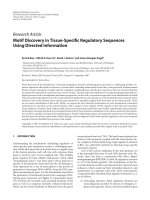
Báo cáo hóa học: " Research Article Frequency-Domain Equalization in Single-Carrier Transmission: Filter Bank Approach" doc
Bạn đang xem bản rút gọn của tài liệu. Xem và tải ngay bản đầy đủ của tài liệu tại đây (1.99 MB, 16 trang )
Hindawi Publishing Corporation
EURASIP Journal on Advances in Signal Processing
Volume 2007, Article ID 10438, 16 pages
doi:10.1155/2007/10438
Research Article
Frequency-Domain Equalization in Single-Carrier
Transmission: Filter Bank Approach
Yuan Y ang,
1
Tero Ihalainen,
1
Mika Rinne,
2
and Markku Renfors
1
1
Institute of Communications Engineering, Tampere University of Technology, P.O. Box 553, 33101 Tampere, Finland
2
Nokia Research Center, P. O. Box 407, Helsinki 00045, Finland
Received 12 January 2006; Revised 24 August 2006; Accepted 14 October 2006
Recommended by Yuan-Pei Lin
This paper investigates the use of complex-modulated oversampled filter banks (FBs) for frequency-domain equalization (FDE) in
single-carrier systems. The key aspect is mildly frequency-selective subband processing instead of a simple complex gain factor per
subband. Two alternative low-complexity linear equalizer structures with MSE criterion are considered for subband-wise equal-
ization: a complex FIR filter structure and a cascade of a linear-phase FIR filter and an allpass filter. The simulation results indicate
that in a broadband wireless channel the performance of the studied FB-FDE structures, with modest number of subbands, reaches
or exceeds the performance of the widely used FFT-FDE system with cyclic prefix. Furthermore, FB-FDE can perform a significant
part of the baseband channel selection filtering. It is thus observed that fractionally spaced processing provides significant perfor-
mance benefit, with a similar complexity to the symbol-rate system, when the baseband filtering is included. In addition, FB-FDE
effectively suppresses narrowband interference present in the signal band.
Copyright © 2007 Yuan Yang et al. This is an open access article distributed under the Creative Commons Attribution License,
which permits unrestricted use, distribution, and reproduction in any medium, provided the original work is properly cited.
1. INTRODUCTION
Future wireless communications must provide ever increas-
ing data transmission rates to satisfy the growing demands of
wireless networking. As symbol-rates increase, the intersym-
bol interference, caused by the bandlimited time-dispersive
channel, distorts the transmitted signal even more. The
difficulty of channel equalization in single-carrier broad-
band systems is thus regarded as a major challenge to high-
rate transmission over mobile radio channels. Single-carrier
time-domain equalization has become impractical because
of the high computational complexity of needed transversal
filters with a high number of taps to cover the maximum de-
lay spread of the channel [1]. This has lead to extensive re-
search on spread spectrum techniques and multicarrier mod-
ulation. On the other hand, single-carrier transmission has
the benefit, especially for uplink, of a very simple transmit-
ter architecture, which avoids, to a large extent, the peak-
to-average power ratio problems of multicarrier and CDMA
techniques. In recent years, the idea of single-carrier trans-
mission in broadband wireless communications has been
revived through the application of frequency-domain equal-
izers, which have clearly lower implementation complexity
than time-domain equalizers [1–3]. Both linear and decision
feedback structures have been considered. In [2, 4–6], it has
been demonstr ated that the single-carrier frequency-domain
equalization may have a performance advantage and that it
is less sensitive to nonlinear distortion and carrier synchro-
nization inaccuracies compared to multicarrier modulation.
The most common approach for FDE is based on
FFT/IFFT transforms between the time and frequency do-
mains. Usually, a cyclic prefix (CP) is employed for the trans-
mission blocks. Such a system can be derived, for exam-
ple, from OFDM by moving the IFFT from the transmit-
ter to the receiver [4]. FFT-FDEs with CP are character-
ized by a flat-fading model of the subband responses, which
means that one complex coefficient per subband is sufficient
for ideal linear equalization. This approach has overhead in
data transmission due to the guard interval between symbol
blocks. Another approach is to use overlapped processing of
FFT blocks [7–9] which allows equalization without CP. This
results in a highly flexible FDE concept that can basically be
used for any single-carrier system, including also CDMA [8].
This paper develops high performance single-carrier
FDE techniques without CP by the use of highly frequency-
selective filter banks in the analysis-synthesis configuration,
instead of the FFT and IFFT transforms. We examine the
use of subband equalization for mildly frequency-selective
2 EURASIP Journal on Advances in Signal Processing
subbands, which helps to reduce the number of subbands
required to achieve close-to-ideal performance. This is facil-
itated by utilizing a proper complex, partially oversampled
filter bank structure [10–13].
One central choice in the FDE design is between symbol-
spaced equalizers (SSE) and fractionally spaced equalizers
(FSE) [3, 14]. An ideal receiver includes a matched filter
with the channel matched part, in addition to the root raised
cosine (RRC) filter, before the symbol-rate sampling. SSE
ignores the channel matched part, leading to performance
degradation, whereas FSEs are, in principle, able to achieve
ideal linear equalizer performance. However, symbol-rate
sampling is often used due to its simplicity. In frequency-
domain equalization, FSE can be done by doubling the num-
ber of subbands and the sampling rate at the filter bank input
[1, 3, 6]. This paper examines also the performance and com-
plexity tradeoffs of the SSE and FSE structures.
The main contribution of this paper is an efficient com-
bination of analysis-synthesis filter bank system and low-
complexity subband-wise equalizers, applied to frequency-
domain equalization. The filter bank has a complex I/Q in-
put and output signals suitable for processing baseband com-
munication signals as such, so no additional single sideband
filtering is needed in the receiver (real analysis-synthesis
systems cannot be easily adapted to this application). The
filter bank also has oversampled subband signals to fa-
cilitate subband-wise equalization. We consider two low-
complexity equalizer structures operating subband-wise: (i)
a 3-tap complex-valued FIR filter (CFIR-FBEQ), and (ii)
the cascade of a low-order allpass fi lter as the phase equal-
izer and a linear-phase FIR filter as the amplitude equalizer
(AP-FBEQ). In the latter structure, the amplitude and phase
equalizer stages can be adjusted independently of each other,
which turns out to have several benefits. Simple channel esti-
mation based approaches for calculation of the equalizer co-
efficients both in SSE and FSE configurations and for both
equalizer structures are developed. Further, the benefits of
FB-FSEs in contributing significantly to the receiver selectiv-
ity will be addressed.
In a companion paper [15], a similar subband equalizer
structure is utilized in filter bank based multicarrier (FBMC)
modulation, and its performance is compared to a refer-
ence OFDM modulation in a doubly dispersive broadband
wireless communication channel. In this paper, we continue
with the comparisons of OFDM, FBMC, single-carrier FFT-
FDE, and FB-FDE systems. The key idea of our equalizer con-
cept has been presented in the earlier work [16] together with
two of the simplest cases of the subband equalizer.
The content of this paper is organized as follows:
Section 2 gives an overview of FFT-SSE and FFT-FSE. In ad-
dition, the mean-squared error (MSE) criterion based sub-
band equalizer coefficients are derived. Section 3 addresses
the exponentially modulated oversampled filter banks and
the subband equalization struc tures, CFIR-FBEQ and AP-
FBEQ. The particular low-complexity cases of these st ruc-
tures are presented, together with the formulas for calcu-
lating the equalizer coefficients from the channel estimates.
Also, the channel estimation principle is briefly described.
Section 4 gives numerical results, including simulation re-
sults to illustrate the effects of filter bank and equalizer pa-
rameters on the system performance. Then detailed compar-
isons of the studied FB-SSE and FB-FSE structures w ith the
reference systems are given.
2. FFT BASED FREQUENCY-DOMAIN EQUALIZATION
IN A SINGLE-CARRIER TRANSMISSION
Throughout this paper, we consider single-carrier block
transmission over a linear bandlimited channel with addi-
tive white Gaussian noise. We assume that the channel has
time-invariant impulse response during each block transmis-
sion. For each block, a CP is inserted in front of the block, as
shown in Figure 1. In this case, the received signal is obtained
as a cyclic convolution of the transmitted signal and channel
impulse response. Therefore, the channel frequency response
is accurately modeled by a complex coefficient for each fre-
quency bin [17]. The length of the CP extension is P
≥ L,
where L is the maximum length of the channel impulse re-
sponse. The CP includes a copy of information symbols from
the tail of the block. This results in bandwidth efficiency re-
duction by the factor M/(M+P), where M is the length of the
information symbol block. In general, for time-varying wire-
less environment, M is chosen in such a way that the channel
impulse response can be considered to be static during each
block transmission.
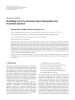
The block diagram of a communication link with FFT-
SSE and FFT-FSE is shown in Figure 1. The operations of
the equalization include the forward transform from time to
frequency domain, channel inversion, and the reverse trans-
form from frequency to time domain. The CP is inserted
after the symbol mapping in the transmitter and discarded
before equalization in the receiver. At the transmitter side, a
block of M symbols x(m), m
= 0, 1, , M − 1, is oversam-
pled and transmitted with the average power σ
2
x
.Thereceived
oversampled signal r(n)canbewrittenas
r(n)
= x(n) ⊗ c(n)+v(n),
c(n)
= g
T
(n) ⊗ h
ch
(n) ⊗ g
R
(n).
(1)
Here v(n) is additive white Gaussian noise with variance σ
2
n
.
The symbol
⊗ represents convolution, h
ch
(n) is the channel
impulse response, and g
T
(n)andg
R
(n) are the transmit and
receive filters, respectively. They are both RRC filters with the
roll-off factor α
≤ 1 and the total signal bandwidth B = (1 +
α)/T,withT denoting the symbol duration.
Generally in the paper, the lowercase letters will be used
for time-domain notations and the uppercase letters for
frequency-domain notations. The letter n is used for time-
domain 2
× symbol-rate data sequences and m for symbol-
rate sequences, while the script k represents the index of
frequency-domain subband signals. For example, in Figure 1,
R
k
is the received signal of kth subband, and W
k
and
W
k
rep-
resent the kth subband equalizer coefficients of SSE and FSE,
respectively.
Yuan Yang et al. 3
Bits
0010111010
Symbol
mapping
x(m)
CP
insertion
2
x(n)
Tx filter
g
T
(n)
Channel
h
ch
(n)
+
Additive noise
v(n)
Symbol-spaced
equalizer
Rx filter
g
R
(n)
x(m) x(m)
P/S
.
.
.
.
.
.
.
.
.
.
.
.
M-IFFT
X
0
X
1
X
M 1
+
+
W
0
W
1
W
M 1
R
0
R
1
R
M 1
M-FFT
S/P
r(m)
2
CP
removal
x(m)
Fractionally-spaced
equalizer
x(m)
P/S M-IFFT
.
.
.
X
0
.
.
.
X
M 1
W
0
W
M 1
W
M
W
2M 1
.
.
.
.
.
.
R
0
R
M 1
2M-FFT
R
M
R
2M 1
.
.
.
S/P
r(n)
CP
removal
CP
P symbols
Data
M symbols
One block
Figure 1: General model of FFT-SSE and FFT-FSE for single-carrier frequency-domain equalization.
2.1. Symbol-spaced equalizer
Suppose that c
SSE
(m) is the symbol-rate impulse response of
the cascade of transmit filter g
T
(n), channel h
ch
(n), and re-
ceiver filter g
R
(n), and C
SSE
k
is the kth bin of its DFT trans-
form, the DFT length being equal to the symbol block length
M. Assuming that the length of the CP is sufficient, that is,
longer than the delay spread of c
SSE
(n), we can express the
kth subband sample as
R
k
= C
SSE
k
X
k
+ N
k
, k = 0, 1, , M − 1, (2)
where X
k
is the ideal noise- and distortion-free sample and
N
k
is zero mean Gaussian noise. The equalized frequency-
domain samples are
X
k
= W
k
R
k
, k = 0, 1, , M−1. After the
IFFT, the equalized time-domain signal
x(m) is processed by
a slicer to get the detected symbols
x( m). The error sequence
at the slicer is e(m)
= x(m) − x(m) and MSE is defined as
E[
|e(m)|
2
].
The subband equalizer optimization criterion could be
zero forcing (ZF) or MSE. In this paper, we are focus-
ing on wideband single-carrier transmission, with heavily
frequency-selective channels. In such cases, the ZF equaliz-
ers suffer from severe noise enhancement [14]andMSEpro-
vides clearly better performance. We consider here only the
MSE criterion.
To minimize MSE, considering the residual intersymbol
interference and additive noise, the frequency response of the
optimum linear equalizer is given by [14]
W
k
=
C
SSE
k
∗
C
SSE
k
2
+ σ
2
n
σ
2
x
,(3)
where k
= 0, 1, , M − 1and(·)
∗
represents complex con-
jugate.
2.2. Fractionally-spaced equalizer
The FFT-FSE, shown in Figure 1,operatesat2
× symbol-rate,
2/T. In some papers, it is also named as T/2-spaced equalizer
[14, 18]. For each transmitted block, the received samples are
processed using a 2M-point FFT. The RRC filter block at the
receiver is absent since it can be realized together with the
equalizer in the frequency domain [1].
In the case of SSE, the folding is carried out before equal-
ization, where the folding frequency is 1/2T. It is evident in
Figure 2 that uncontrolled aliasing over the transition band
F
1
takes place. This means that SSE can only compensate for
the channel distortion in the aliased received signal, which
results in performance loss. On the other hand, FSE com-
pensates for the channel distortion in received signal before
the aliasing takes place. After equalization, the aliasing takes
4 EURASIP Journal on Advances in Signal Processing
FSE
SSE
α
1/T 1/2T 01/2T 1/T 3/2T 2/T
F
2
F
1
F
2
F
1
F
0
F
0
F
1
F
2
T
α
Passband
Transition band
Stopband
Symbol duration
Roll-off
Figure 2: Signal spectra in the cases of SSE and FSE.
place in an optimal manner. The performance is expected to
approach the performance of an ideal linear equalizer.
Let H
ch
k
, k = 0, 1, ,2M − 1, denote the 2M-point
DFT of the T/2-spaced channel impulse response, and G
k
denote the RRC filter in the transmitter or in the receiver
side. Assuming zero-phase model for the RRC filters, G
k
is
always real-valued. The optimum linear equalizer model in-
cludes now the following elements: transmitter RRC filter,
channel h
ch
(n), matched filter including receiver RRC fil-
ter and channel matched filter h
∗
ch
(−n), resampling at the
symbol-rate, and MSE linear equalizer at symbol-rate. The
2
×-oversampled system frequency response can be written
as
Q
k
= G
k
H
ch
k
H
ch
k
∗
G
k
=
C
FSE
k
2
G
k
2
,
C
FSE
k
= H
ch
k
G
k
2
.
(4)
Here C
FSE
k
is the kth bin of DFT transform of the T/2-spaced
impulse response of the cascade of the channel and the two
RRC filters. The channel estimator described in Section 3.4
provides estimates for C
FSE
k
. Now the frequency bins k and
M + k carry redundant information about the same subband
data, just weighted differently by the RRC filters and the
channel. The folding takes place in the sampling r a te reduc-
tion, adding up these pairs of frequency bins. Before the ad-
dition, it is important to compensate the channel phase re-
sponse so that the two bins are combined coherently, and
also to weight the amplitudes in such a way that the SNR
is maximized. The maximum ratio combining idea [1]and
the sampled matched filter model [14] lead to the same re-
sult. Combining this front-end model with the MSE linear
equalizer leads to the following expression for the optimal
subband equalizer coefficients:
W
k
=
C
FSE
k
∗
G
k
Q
k
+
Q
(M+k)
mod(2M)
+ σ
2
n
σ
2
x
. (5)
The frequency index k
= 0, 1, ,2M − 1 covers the entire
spectrum [0, 2π]asω
k
= 2πk/2M, that is, k = 0 corresponds
to DC and k
= M corresponds to the symbol-rate 1/T.It
should be noted that here the equalizer coefficients imple-
ment the whole matched filter together w ith the MSE equal-
izer. The whole spectrum, where the equalization takes place,
that is, the FFT frequency bins, can be grouped into three fre-
quency regions with different equalizer actions.
(i) Passbands F
0
: k ∈ [0, (1 − α)M/2] ∪ [(3 + α)M/2,
2M
− 1].
There is no aliasing in these two regions, so the equal-
izer coefficients can be written in simplified form as
W
k
=
C
FSE
k
∗
G
k
Q
k
+ σ
2
n
σ
2
x
. (6)
(ii) Transition bands F
1
: k ∈ [(1 − α)M/2, (1 + α)M/2] ∪
[(3 − α)M/2, (3 + α)M/2].
Aliasing takes place when the received signal is folded,
and (5) should be used.
(iii) Stopbands F
2
: k ∈ [(1 + α)M/2, (3 − α)M/2].
Only noise and interference components are included
and all subband signals can be set to zero,
W
k
= 0.
The use of oversampling provides robustness to the sam-
pling phase. Basically the frequency-domain equalizer imple-
ments also sy mbol-timing adjustment. Furthermore, com-
pared with the SSE system, the receiver filter of the FSE sys-
tem can be implemented efficiently in the frequency domain.
This means that the pulse shaping filtering will not intro-
duce additional computational complexity, even if it has very
sharp transition bands.
2.3. Computational complexity of SSE and FSE
In the following example, we will count the real multiplica-
tions at the receiver side. The complexity mainly comes from
RRC filtering, FFT and IFFT, and equalization.
(i) Suppose that M
= 512 symbols are transmitted in a
block. The number of the received samples is 2M
=
1024 because of the oversampling by 2.
(ii) Each subband equalizer has only one complex weight,
resulting in 4 real multiplications per subband.
(iii) The pulse shaping filter is an RRC filter with the roll-
off factor of α
= 0.22 and the length of N
RRC
= 31.
Because of symmetry, only (N
RRC
+1)/2 = 16 multi-
pliers are needed for the RRC filtering in the SSE. In
an efficient decimation structure, (N
RRC
+1)/2multi-
plications per symbol are needed, both for the real and
imaginary parts of the received signal.
(iv) The split-radix algorithm [19] is applied to the FFT.
For an M-point FFT, M(log
2
M − 3) + 4 real multipli-
cations are needed.
(v) In the case of SSE, the total number of real multiplica-
tions per symbol is about (N
RRC
+1)+2 log
2
M−2 ≈ 48.
(vi) In the case of FSE, the number of subbands used is
M(1 + α). The total number of real multiplications per
symbol is about 3 log
2
M − 3+4α ≈ 25.
From the above discussion, we can easily conclude that FFT-
FSE has lower rate of real multiplications than FFT-SSE. This
is mainly due to the reason that much of the complexity is
saved when the RRC filter is realized in frequency domain.
Yuan Yang et al. 5
60
50
40
30
20
10
0
Amplitude (dB)
00.10.20.30.40.50.60.70.80.91
Frequency ω/π
(a) DFT bank
60
40
20
0
Amplitude (dB)
00.10.20.30.40.50.60.70.80.91
Frequency ω/π
(b) EMFB
Figure 3: Comparison of the subband frequency responses of DFT and EMFB.
Bits
0010111010
Symbol mapping
x(m)
2
Tx filter
g
T
(n)
Channel
h
ch
(n)
+
v(n)
x(m) x(m)
2+
j
Critically sampled
synthesis banks
CMFB
SMFB
Re
Re
Re
Re
.
.
.
.
.
.
R
0
R
2M 1
Equalizer
.
.
.
.
.
.
j
j
+
+
+
+
+
+
+
+
2x-oversampled
analysis banks
r(n)
Re
Im
.
.
.
.
.
.
.
.
.
.
.
.
CMFB
SMFB
SMFB
CMFB
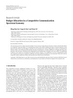
Figure 4: Generic FB-FDE system model in the FSE case.
3. EXPONENTIALLY MODULATED FILTER
BANK BASED FDE
Filter banks provide an alternative way to perform the sig-
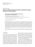
nal transforms between time and frequency domains, in-
stead of FFT. As shown in Figure 3, exponentially modu-
lated FBs (EMFBs) achieve better frequency selec tivity than
DFT banks, but they have the drawback that, since the basis
functions are overlapping and longer than a symbol block,
the CP cannot be utilized. Consequently, the subbands can-
not b e considered to have flat frequency responses. However,
the lack of CPs can be considered a benefit, since CPs add
overhead and reduce the spectral efficiency. Furthermore, in
the FSE case, frequency-domain filtering with a filter bank is
quite effective in suppressing strong interfering spectral com-
ponents in the stopband regions of the RRC filter.
Figure 4 shows the FB-FSE model including a complex
exponentially modulated analysis-synthesis filter bank struc-
ture as the core of frequency-domain processing. The filter
bank structure has complex baseband I/Q signals as its input
and output, as required for spectrally efficient radio commu-
nications. The sampling rate conversion factor in the analysis
and synthesis banks is M, and there are 2M low-rate sub-
bands equally spaced between [0, 2π]. In the critically sam-
pled case, this FB has a real format for the low-rate subband
signals [12].
3.1. Exponentially modulated filter bank
EMFB belongs to a class of filter banks in which the subfil-
ters are formed by modulating an exponential sequence with
the lowpass prototype impulse response h
p
(n)[11, 12]. Ex-
ponential modulation translates H
p
(e
jω
)(lowpassfrequency
response of the prototype filter) to a new center frequency
determined by the subband index k. The prototype filter
h
p
(n) can be optimized in such a manner that the filter
bank satisfies the perfect reconstruction condition, that is,
6 EURASIP Journal on Advances in Signal Processing
the output signal is purely a delayed version of the input sig-
nal. In the general form, the EMFB synthesis filters f
e
k
(n)and
analysis filters g
e
k
(n)canbewrittenas
f
e
k
(n) =
2
M
h
p
(n)exp
j
n +
M +1
2
k +
1
2
π
M
,
g
e
k
(n)=
2
M
h
p
(n)exp
−
j
N
B
−n +
M +1
2
k +
1
2
π
M
,
(7)
where n
= 0, 1, , N
B
and subband index k = 0, 1, ,2M −
1. Furthermore, it is assumed that the subband filter order is
N
B
= 2KM−1. The overlapping factor K can be used as a de-
sign parameter because it affects how much stopband attenu-
ation can be achieved. Another essential design parameter is
the stopband edge of the prototype filter ω
s
= (1 + ρ)π/2M,
where the roll-off parameter ρ determines how much adja-
cent subbands overlap. Typically, ρ
= 1.0 is used, in which
case only the neighboring subbands are overlapping with
each other, and the overall subband bandwidth is twice the
subband spacing.
The amplitude responses of the analysis and synthesis fil-
ters divide the whole frequency range [0, 2π] into equally
wide passbands. EMFB has odd channel stacking, that is, kth
subbandiscenteredatthefrequency(k +1/2)π/M.After
decimation, the even-indexed subbands have their passbands
centered at π/2 and the odd-indexed at
−π/2. This unsym-
metry has some implications in the later formulations of the
subband equalizer design.
In our approach, EMFB is implemented using cosine-
and sine-modulated filter bank (CMFB/SMFB) blocks [11,
12], as can be seen in Figure 4. The extended lapped trans-
form is an efficient method for implementing perfect re-
construction CMFBs [20]andSMFBs[21]. The relations
between the 2M-channel EMFB and the corresponding M-
channel CMFB and SMFB with the same real prototype are
f
e
k
(n)=
⎧
⎪
⎨
⎪
⎩
f
c
k
(n)+ jf
s
k
(n), k ∈ [0, M − 1],
−
f
c
2M
−1−k
(n) − jf
s
2M
−1−k
(n)
, k ∈ [M,2M−1],
g
e
k
(n)=
⎧
⎪
⎨
⎪
⎩
g
c
k
(n) − jg
s
k
(n), k ∈ [0, M − 1],
−
g
c
2M
−1−k
(n)+ jg
s
2M
−1−k
(n)
, k ∈ [M,2M−1],
(8)
where g
c
k
(n)andg
s
k
(n) are the analysis CMFB/SMFB subfilter
impulse responses, f
c
k
(n)and f
s
k
(n) are the synthesis bank
subfilter responses (the superscript denotes the type of mod-
ulation). They can be genera ted according to (7).
One additional feature of the structure in Figure 4 is that,
while the synthesis filter bank is critically sampled, the sub-
band output signals of the analysis bank are oversampled by
the factor of two. This is achieved by using the complex I/Q
subband sig nals, instead of the real ones which would be suf-
ficient for reconstructing the analysis bank input signal in the
synthesis bank when no subband processing is used [10, 13]
(in a critically sampled implementation, the two lower most
blocks of the analysis bank of Figure 4 would be omitted).
For a block of M complex input samples, 2M real subband
samples are generated in the critically sampled case and 2M
complex subband samples are generated in the oversampled
case.
The advantage of using 2
×-oversampled analysis filter
bank is that the channel equalization can be done within
each subband independently of the other subbands. Assum-
ing roll-off ρ
= 1.0 or less in the filter bank design, the
complex subband signals of the analysis bank are essentially
alias-free. This is because the aliasing signal components are
attenuated by the stopband attenuation of the subband re-
sponses. Subband-wise equalization compensates the chan-
nel frequency response over the whole subband bandwidth,
including the passband and transition bands. The imaginary
parts of the subband signals are needed only for equalization.
The real parts of the subband equalizer outputs are sufficient
for synthesizing the time-domain equalized signal, using a
critically sampled synthesis filter bank.
It should be mentioned that an alternative to oversam-
pled subband processing is to use a critically sampled anal-
ysis bank together with subband processing algorithms that
have cross-connections between the adjacent subbands [22].
However, we believe that the oversampled model results in
simplified subband processing algorithms and competitive
complexity.
After the synthesis bank, the time-domain symbol-rate
signal is fed to the detection device. In the FSE model of
Figure 4, the synthesis bank output signal is downsampled to
the symbol-rate. In the case of FSE with frequency-domain
folding, an M-channel synthesis bank would be sufficient,
instead of the 2M-channel bank. The design of such a fil-
ter bank system in the nearly perfect reconstruction sense is
discussed in [23].
We consider here the use of EMFB which has odd channel
stacking, that is, the center-most pair of subbands is symmet-
rically located around the zero frequency at the baseband.
We could equally well use a modified EMFB structure [13]
with even channel stacking, that is, center-most subband is
located symmetr ically around the zero frequency, which has
a slightly more efficient implementation structure based on
DFT processing. Also modified DFT filter banks [24]could
be utilized with some modifications in the baseband process-
ing. However, the following analysis is based on EMFBs since
they result in the most straightforward system model.
Further, the discussion is based on the use of perfect re-
construction filter banks, but also nearly perfect reconstruc-
tion (NPR) designs could be utilized, which usually result in
shorter prototype filter length. In the critically sampled case,
the implementation benefits of NPR are limited, because the
efficient extended lapped transform structures cannot be uti-
lized [12]. However, in the 2
×-oversampled case, having par-
allel CMFB and SMFB blocks, the implementation benefit of
the NPR designs could be significant.
3.2. Channel equalizer structures and designs
In the filter bank, the number of subbands is selected in such
a way that the channel is mildly frequency selective within
Yuan Yang et al. 7
each individual subband. We consider here several low-
complexity subband equalizers which are designed to
equalize the channel optimally at a small number of selected
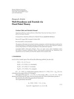
frequency points within each subband. Figure 5 shows one
example, where the subband equalizer is determined by the
channel response of three selected frequency points, one at
the center frequency, the other two at the subband edges. In
this example, the ZF criterion is used for equalization, that
is, the channel frequency response is exactly compensated at
those selected frequency points.
3.2.1. CFIR-FBEQ
A very basic approach is to use a complex FIR filter as a sub-
band equalizer. A 3-tap FIR filter,
1
E
CFIR
(z) = c
0
z+c
1
+c
2
z
−1
,
has the required degrees of freedom to equalize the channel
frequency response within each subband.
It should be noted that the subband equalizer response
depends on the number of frequency points considered
within each subband. Regarding the choice of the specific
frequency points, the design can be greatly simplified when
the choice is among the normalized frequencies ω
= 0, ±π/2,
and
±π. At the selected frequency points, the equalizer is de-
signed to take the target values given by (5) in the FSE case
and by (3) in the SSE case. Below we focus on the MSE based
FSE.
When three subband frequency points are selected in
the subband equalizer design, there are a total of 4M fre-
quency points for 2M subbands, that is, we consider the MSE
equalizer response
W
κ
at equally spaced frequency points
κπ/(2M), κ
= 0, 1, ,4M − 1. For notational convenience,
we define the target frequency responses in terms of subband
index k
= 0, 1, ,2M − 1, instead of frequency point index
κ.Thekth subband target response value is denoted as η
ik
,
which is defined as
η
ik
=
W
2k+i
, i = 0, 1,2. (9)
At the low rate after decimation, these frequency points
{η
0k
, η
1k
, η
2k
} are located for the even subbands at the nor-
malized frequencies ω
= {0, π/2, π}, and for the odd sub-
bands at the frequencies ω
= {−π, −π/2, 0}. Combining (5)
and (9), we can get the following equations for the subband
equalizer response E
CFIR
(e
jω
) at these target frequencies.
Even subbands:
E
CFIR
k
e
jω
=
⎧
⎪
⎪
⎪
⎪
⎪
⎪
⎨
⎪
⎪
⎪
⎪
⎪
⎪
⎩
c
0k
+ c
1k
+ c
2k
= η
0k
,(ω = 0),
jc
0k
+ c
1k
− jc
2k
= η
1k
,
ω =
π
2
,
−c
0k
+ c
1k
− c
2k
= η
2k
,(ω = π).
(10)
1
In practice, the filter is realized in the causal form z
−1
E
CFIR
(z).
0.6
0.8
1
1.2
1.4
1.6
1.8
2
Amplitude in linear scale
1.5 1 0.50 0.5
Normalized frequency in Fs/2
Amplitude equalizer
ε
0
ε
1
ε
2
Channel response
Equalizer target points ε
i
Equalizer amplitude response
Combined response of channel and equalizer
(a) Amplitude compensation
10
5
0
5
10
15
20
25
Phase (degrees)
0.50 0.511.5
Normalized frequency in Fs/2
Phase equalizer
ξ
0
ξ
1
ξ
2
Channel response
Equalizer target points ξ
i
Equalizer phase response
Combined response of channel and equalizer
(b) Phase compensation
Figure 5: An example of AP-FBEQ subband equalizer responses.
Odd subbands:
E
CFIR
k
e
jω
=
⎧
⎪
⎪
⎪
⎪
⎪
⎪
⎨
⎪
⎪
⎪
⎪
⎪
⎪
⎩
−
c
0k
+ c
1k
− c
2k
= η
0k
,(ω =−π),
− jc
0k
+ c
1k
+ jc
2k
= η
1k
,
ω =
−
π
2
,
c
0k
+ c
1k
+ c
2k
= η
2k
,(ω = 0).
(11)
8 EURASIP Journal on Advances in Signal Processing
Phase equalizer Amplitude equalizer
Phase rotator
b
ck
Σ Σ
ΣΣΣΣ
j
z
1
Re
j
b
ck
z
1
Complex allpass filter
e
jϕ
k
b
rk
z
1
b
rk
Real allpass filter
z
1
z
1
z
1
z
1
z
1
a
2k
a
1k
a
0k
a
1k
a
2k
5-tap symmetric FIR
Figure 6: An example of the AP-FBEQ subband equalizer structure.
The 3-tap complex FIR coefficients {c
0k
, c
1k
, c
2k
} of the
kth subband equalizer can be obtained as follows (+ signs
stand for even subbands and
− signs for odd subbands,
resp.):
c
0k
=±
1
2
η
0k
− η
2k
2
− j
η
1k
−
η
0k
+ η
2k
2
,
c
1k
=
η
0k
+ η
2k
2
,
c
2k
=±
1
2
η
0k
− η
2k
2
+ j
η
1k
−
η
0k
+ η
2k
2
.
(12)
3.2.2. AP-FBEQ
The idea of AP-FBEQ approach is to compensate channel
amplitude and phase distortion separately. In other words,
at those selected frequency points, the amplitude response
of the equalizer is proportional to the inverse of the channel
amplitude response, and the phase response of the equalizer
is the negative of the channel phase response.
The subband equalizer structure, shown in Figure 6,isa
cascade of a phase equalization section, consisting of allpass
filter stages and a phase rotator, and an amplitude equaliza-
tion section, consisting of a linear-phase FIR filter. This par-
ticular structure makes it possible to design the amplitude
equalization and phase equalization independently, leading
to simple formulas for channel estimation based solutions,
or simplified and fast adaptive algorithms for adaptive sub-
band equalizers. In this paper, we refer to this frequency-
domain equalization approach as the amplitude-phase filter
bank equalizer, AP-FBEQ.
The real parts of the equalized subband signals are suffi-
cient for constructing the sample sequence for detection, and
the imaginary parts are irrelevant after the subband equaliz-
ers. In the basic form of the AP-FBEQ subband equalizer, the
operation of taking the real part would be after all the fil-
ters of the subband equalizer. But since the real filters (real
allpass and magnitude equalizer) act independently on the
real (I) and imaginary (Q) branch signals, the results of the
Q-branch computations after the phase rotator would never
be utilized. Therefore, it is possible to move the real part
operation and combine it with the phase rotator, that is,
only the real part of the phase rotator output needs to be
calculated, and the real filters are implemented only for the
I-branch. The structure of Figure 6 is completely equivalent
with the original one, but it is computationally much more
efficient. With the same kind of reasoning, it is easy to see that
in the CFIR-FBEQ case, only two real multipliers are needed
to implement each of the taps.
The orders of the equalizer sections, as well as the num-
ber of specific frequency points used in the subband equalizer
design, offer a degree of freedom and are chosen to obtain
a low-complexity solution. Firstly, we consider the subband
equalizer structure shown in Figure 6. The transfer functions
of the complex and real first-order allpass filters A
c
k
(z)and
A
r
k
(z)canbegivenby
2
A
c
k
(z) =
1 − jb
ck
z
1+ jb
ck
z
−1
,
A
r
k
(z) =
1+b
rk
z
1+b
rk
z
−1
,
(13)
respectively. The phase response of the equalizer for the kth
subband can be described as
arg
E
AP
k
e
jω
=
arg
e
jϕ
k
· A
c
k
e
jω
·
A
r
k
e
jω
=
ϕ
k
+ 2 arctan
−
b
ck
cos ω
1+b
ck
sin ω
+ 2 arctan
b
rk
cos ω
1+b
rk
sin ω
.
(14)
The equalizer magnitude response for the kth subband can
be written as
E
AP
k
e
jω
=
a
0k
+2a
1k
cos ω +2a
2k
cos 2ω
. (15)
The AP-FBEQ idea can be a pplied to both SSE and FSE
in similar manner as CFIR-FBEQ. Here, we focus on the
FSE case. Three subband frequency points at normalized
frequencies ω
={0, π/2, π} for the even subbands and ω=
{−π, −π/2, 0} for the odd subbands are selected in the sub-
band equalizer design. Here, we define the target amplitude
2
The allpass filters can be realized in the causal form z
−1
A
k
(z).
Yuan Yang et al. 9
and phase response values for subband k as
ik
and ζ
ik
,re-
spectively:
ik
=
W
2k+i
,
ζ
ik
= arg
W
2k+i
, i = 0, 1,2.
(16)
Then, combining (5), (14), (15), and (16) at these tar-
get frequencies, we can der ive two allpass filter coefficients
{b
ck
, b
rk
} and a phase rotator ϕ
k
for phase compensation
section and the FIR coefficients
{a
0k
, a
1k
, a
2k
} for amplitude
compensation.
In this paper, the following three different low-complex-
ity designs of the AP-FBEQ structure are considered. (+ signs
stand for the even subbands and
− signs for the odd ones.)
Case 1. One frequency point is selected in the subband. This
model of subband equalizer consists only of the phase rota-
tor e
jϕ
k
for phase compensation and a real coefficient a
0k
for
amplitude compensation. In fact, it behaves like one com-
plex equalizer coefficient for each subband in the FFT-FDE
system. The subband center frequency point is selected to de-
termine the equalizer response
ϕ
k
= ζ
1k
, a
0k
=
1k
. (17)
Case 2. Two frequency points are selected at the subband
edges at the frequency points ω
= 0and±π to determine the
equalizer coefficients. The subband equalizer st ructure con-
sists of a cascade of a first-order complex allpass filter fol-
lowed by a phase rotator and an operation of taking the real
part of the signal. Finally, a symmetr ic linear-phase 3-tap FIR
filter is applied for amplitude compensation. In this case, the
equalizer coefficients can be calculated as
ϕ
k
=
ζ
0k
+ ζ
2k
2
, a
0k
=
1
2
0k
+
2k
,
b
ck
=±tan
ζ
2k
− ζ
0k
4
, a
2k
=±
1
4
0k
−
2k
.
(18)
Case 3. Three frequency points are used in each subband, as
we have discussed above, one at the subband center and two
at the passband edges. The equalizer structure contains two
allpass filters, a phase rotation stage and a symmetric linear-
phase 5-tap FIR filter. Their coefficients are calculated as be-
low:
ϕ
k
=
ζ
0k
+ ζ
2k
2
, a
0k
=
0k
+2
1k
+
2k
4
,
b
ck
=±tan
ζ
2k
− ζ
0k
4
, a
1k
=±
0k
−
2k
4
,
b
rk
=±tan
ζ
1k
− ϕ
k
2
, a
2k
=±
0k
− 2
1k
+
2k
8
.
(19)
The subband equalizer structure is not necessarily fixed
in advance but can be determined individually for each
subband based on the frequency-domain channel estimates.
This enables the structure of each subband equalizer to be
controlled such that each subband response is equalized op-
timally at the minimum number of frequency points which
can be expected to result in sufficient performance.
The performances of these three different subband equal-
izer designs, together with the 3-tap CFIR-FBEQ, will be ex-
amined in the next section.
3.3. FSE and SSE
Also in the SSE version of CFIR-FBEQ and AP-FBEQ, the
decimating RRC filtering needs to be carried out before
equalization, and uncontrolled aliasing results in similar per-
formance loss as in the FFT-SSE.
In the FSE, the receiver RRC filter can again be imple-
mented in the frequency domain together with the equalizer,
with low complexity. Since no guard interval is employed
and the subbands are highly frequency selective, frequency-
domain filtering can be implemented independently of the
roll-off and other filtering requirements, as long as the
stopband attenuation in the filter bank design is sufficient
for the receiver filter from the RF point of v iew. It can be
noted that the FB-FSE structure provides a flexible solution
for channel equalization and channel filtering, since the re-
ceiver filter bandwidth and roll-off can be controlled by ad-
justing the RRC-filtering part of the equalizer coefficient cal-
culations.
In advanced receiver designs, a hig h initial sampling rate
is often utilized, followed by a multistage decimation fil-
ter chain which is highly optimized for low-implementation
complexity [25]. The first stages of the decimation chain of-
ten utilize multiplier-free structures, like the cascaded inte-
grator comb, and the major part of the implementation com-
plexity is at the last stage. In such designs, FB-FSE provides a
flexible generic solution for the last stage of a channel filter-
ing chain.
3.4. Channel estimation
FB-FDEs, as well as FFT-FDEs, can be implemented by us-
ing adaptive channel equalization algorithms to adjust the
equalizer coefficients. However, we focus here on channel
estimation based approach, where the equalizer coefficients
are calculated at regular inter vals based on the channel esti-
mates and knowledge of the desired receiver filter frequency
response, according to (3)or(5). In the performance studies,
we have utilized a basic, maximum likelihood (ML) channel
estimation method (also known as the least-squares method)
using training sequences [26]. Here, Gold codes [27]ofdif-
ferent lengths are used as training sequences.
In SSE, a training sequence is transmitted, and the
symbol-rate channel impulse response (including tr ansmit-
ter and receiver RRC filters) is estimated based on the re-
ceived training sequence at the decimating RRC filter output.
This channel estimate is used for calculating the equalizer co-
efficients using (3).
10 EURASIP Journal on Advances in Signal Processing
In FSE, we have chosen to estimate T/2-spaced impulse
responses (including the two RRC filters). Including the re-
ceiver RRC filter in the estimated response minimizes the
noise and interference coming into the channel estimator.
Now, the channel estimator utilizes the receiver RRC fil-
ter output at two times the symbol-rate. It must be noted
that this approach requires a time-domain RRC filter for the
training sequences in the receiver, even if frequency-domain
filtering is applied to the data symbols.
4. NUMERICAL RESULTS
4.1. Basic simulations and numerical comparisons
The considered models of FFT-FDE and FB-FDE were intro-
duced in Figures 1 and 4, respectively. The pulse shaping fil-
ters both in the transmitter and receiver are real-valued RRC
filters with α
= 0.22. In the FSE case, the receiver RRC filter
is realized by the equalizer. The filter bank designs in the sim-
ulations used roll-off ρ
= 1.0, different numbers of subbands
2M
={128, 256} and overlapping factors K ={2, 3, 5},re-
sulting in about 30 dB, 38 dB, and 50 dB stopband attenua-
tions, respectively.
The performances were tested using the extended
vehicular-A channel model of ITU-R with the maximum ex-
cess delay of about 2.5 μs[28]. The symbol-rate was 1/T
=
15.36 MHz. The channel fading was modelled quasistatic,
that is, the channel frequency response was time invariant
during each frame transmission. 4000 independent channel
instances were simulated to obtain the average performance.
The MSE criterion was applied to solve the equalizer coeffi-
cients. The bit-error-rate (BER) performance was simulated
with QPSK, 16-QAM, and 64-QAM modulations, with gray
coding, and was compared to the performance of FFT-FDE.
In all FFT-FDE simulations, the CP is included and assumed
to be longer than the delay spread. Also the performance of
the ideal MSE linear equalizer is included for reference. This
analytic performance reference was obtained by applying the
MSE formula for the infinite-length linear MSE equalizer
from [14] and then using the well-known formulas of the
Q-function and gray-coding assumption for estimating the
BER. The BER measure is averaged over 5000 independent
channel instances. Ideal channel estimation was assumed in
Figures 7, 8,and9, but in Figures 10, 11,and12, the channel
estimator described in Section 3.4 was utilized. The BER and
frame-error-rate (FER) performance with low density parity
check (LDPC) [29] error correction coding are presented in
Figures 11 and 12.
Raw BER performance of FB-FSE
Figure 7 presents the uncoded BER performance of the
CFIR-FBEQ and AP-FBEQ compared to the analytic per-
formance with QPSK, 16-QAM, and 64-QAM modulations.
The three different designs of AP-FBEQ and a 3-tap CFIR-
FBEQ were examined. It can be seen that the CFIR-FBEQ and
AP-FBEQ Case 3 performances are rather similar, however,
with a minor but consistent benefit for AP-FBEQ. With a low
number of subbands and with high-order modulation, the
differences are more visible. In the following comparisons,
AP-FBEQ performance is considered. It is clearly visible that
AP-FBEQ Cases 2 and 3 equalizers improve the performance
significantly compared to Case 1. When the modulation or-
der becomes higher, the performance gaps between differ-
ent equalizer structures increase. As the most interesting un-
coded BER region is between 1% and 10%, it is seen that 256
subbands with Case 3 are sufficient to achieve good perfor-
mance e ven with high-order modulation. The resulting per-
formance is rather close to the analytic BER bound; however,
it is clear that the gray-coding assumption is not very ac-
curate at low E
b
/N
0
, and the analytic performance curve is
somewhat optimistic. With this specific channel model, 128
subbands are sufficient for QPSK and 16-QAM modulations
when AP-FBEQ Case 3 equalizer is used.
The FB design parameter, overlapping factor K,controls
the level of stopband attenuation. Increasing K improves the
stopband attenuation, with the cost of increased implemen-
tation complexity. Figure 8 presents the BER performance
of Case 3 equalizer with 256 subbands and the different K-
factors. For QPSK modulation, it can be seen that the K-
factor has relatively small effect on the performance, and
even K
= 2mayprovidesufficient performance. In the case
of higher order modulations, K
= 3 can achieve sufficient
performance.
SSE versus FSE performance and FFT-FDE versus
FB-FDE comparisons
Figure 9 presents the results for SSE and FSE in the FFT-FDE
and FB-FDE receivers. It is clearly seen that FSE provides sig-
nificant performance gain over SSE in the considered case.
The performance differences between AP-FBEQ and the con-
ventional FFT-FDE methods are relatively small. However,
it should be noted that in Figure 9 the guard-interval over-
head is not taken into account in the E
b
/N
0
-axis scaling, even
though sufficiently long CP (200 samples) is utilized. In prac-
tice, the CP length effects in the BER plots only on the E
b
/N
0
-
axis scaling.
Guard-interval considerations
For example, 10% or 25% guard-interval length would mean
about 0.4 dB or 1 dB degradation on the E
b
/N
0
-axis, respec-
tively. The delay spread of the channel model corresponds
to about 39 symbol-rate samples or 77 samples at twice
the symbol-rate. Then the minimum FFT size to reach 10%
guard-interval overhead is about 350 for SSE and 700 for
FSE. However, the RRC pulse shaping and baseband chan-
nel filtering extend the delay spread, possibly by a factor 2, so
the CP length should be in the order of 5 μs in this example.
Then the practical FFT length could be 512 or 1024 for SSE
and 1024 or 2048 for FSE. The conclusion is that consider-
ably higher number of subbands is needed in the FFT case to
reach realistic CP overhead.
Yuan Yang et al. 11
10
3
10
2
10
1
BER
0 2 4 6 8 10121416
E
b
/N
0
(dB)
AP Case 1; 2M
= 128
AP Case 1; 2M
= 256
AP Case 2; 2M
= 128
CFIR 3-tap; 2M
= 128
AP Case 3; 2M
= 128
AP Case 2; 2M
= 256
CFIR 3-tap; 2M
= 256
AP Case 3; 2M
= 256
Analytic
(a) QPSK
10
2
10
1
10
3
BER
024681012141618
E
b
/N
0
(dB)
AP Case 1; 2M
= 128
AP Case 1; 2M
= 256
AP Case 2; 2M
= 128
CFIR 3-tap; 2M
= 128
AP Case 3; 2M
= 128
AP Case 2; 2M
= 256
CFIR 3-tap; 2M
= 256
AP Case 3; 2M
= 256
Analytic
(b) 16-QAM
10
2
10
1
BER
0 2 4 6 8 1012141618
E
b
/N
0
(dB)
AP Case 1; 2M
= 128
AP Case 1; 2M
= 256
AP Case 2; 2M
= 128
CFIR 3-tap; 2M
= 128
AP Case 3; 2M
= 128
AP Case 2; 2M
= 256
CFIR 3-tap; 2M
= 256
AP Case 3; 2M
= 256
Analytic
(c) 64-QAM
Figure 7: Uncoded BER performance of FB-FSE (CFIR-FBEQ 3-tap and AP-FBEQ Cases 1, 2, 3) with overlapping factor K = 5and
2M
={128, 256} subbands.
Performance with channel estimation
In Figure 10, the uncoded BER performance of AP-FBEQ
is simulated with a practical channel estimator. The chan-
nel estimator described in Section 3.4 is utilized, using Gold
codes of different lengths as a training sequence. It is ob-
served that the training sequence length of 384 sy mbols is
quite sufficient.
4.2. Performance comparison with practical
parameters and error-correction coding
Here, we include LDPC forward error correction (FEC) cod-
ing and the channel estimator in the simulation model. The
main parameters are indicated in Table 1. With the cho-
sen parameters, the training symbol overhead is 10% and
the two systems with different LDPC code-rates transmit
12 EURASIP Journal on Advances in Signal Processing
10
3
10
2
10
1
BER
0 2 4 6 8 1012141618
E
b
/N
0
(dB)
K
= 2
K
= 3
K
= 5
QPSK
16-QAM
64-QAM
Figure 8: Uncoded BER performance for FB-FSE (AP-FBEQ Case 3
equalizer) with 2M
= 256 subbands and different K-factors.
10
3
10
2
10
1
BER
0246810121416
E
b
/N
0
(dB)
SSE; AP-FBEQ Case 3; 2M
= 256
SSE; 2048-FFT
FSE; AP-FBEQ Case 3; 2M
= 256
FSE; 2048-FFT
QPSK
16-QAM
Figure 9: Uncoded BER performance comparison between SSE and
FSE-type FB-FDE and FFT-FDE with QPSK and 16-QAM modu-
lations. AP-FBEQ Case 3 equalizer with 2M
= 256 subbands and
overlapping factor K
= 5 was used.
exactly the same number of source bits per frame. Higher
code-rate is needed in the FFT-FDE system to accommo-
date the CP overhead. Meanwhile, the CP length which is
1/8 of the useful symbol duration introduces E
b
/N
0
degrada-
tion of 10 log
10
(9/8) dB. The comparison of Figure 11 shows
that FB-FDE has about 1 dB performance advantage over the
FFT-FDE under the most interesting coded FER region 1%–
10%. This is the joint results of using lower code-rate and the
absence of CP E
b
/N
0
degradation. Moreover, we can see that
AP-FBEQ and CFIR-FBEQ have very similar performance.
10
3
10
2
10
1
BER
0 2 4 6 8 1012141618
E
b
/N
0
(dB)
128 training sequence
384 training sequence
1024 training sequence
QPSK
16-QAM
64-QAM
Figure 10: Uncoded BER performance for FB-FSE with ML based
channel estimation using different training sequence lengths with
QPSK, 16-QAM, and 64-QAM modulations. AP-FBEQ Case 3
equalizer with 2M
= 256 subbands and overlapping factor K = 5
was used.
The AP-FBEQ and CFIR-FBEQ systems are also com-
pared in Figure 12 w ith the FBMC and OFDM systems of
[15]. The parameters of FB-FDE are the same as in Table 1,
except that code-rate 3/4 is used to reach similar bits rate with
the other systems. The parameters are consistent with the
ones considered in [15], with similar overhead for training
sequences/pilots, signal bandwidth, and bit rates. The same
type of LDPC code is used, however with higher code-rate
3/4 in OFDM and FB-FDE, and code-rate 2/3intheFBMC
system. Higher code-rate is needed in OFDM to accomodate
the CP-overhead and FB-FDE to accommodate the overhead
due to the excess band. With QPSK modulation, the number
of source bits in one 250 μs frame are 5022, 5184, and 5320
for OFDM, FB-FDE, and FBMC, respectively.
Figure 12 displays that with QPSK modulation, FB-FDE
has clear performance benefit over FBMC and CP-OFDM;
whereas with 16-QAM modulation, FB-FDE and CP-OFDM
are rather similar and clearly worse than that of FBMC.
4.3. Complexity comparison between FFT-FDEs
and FB-FDEs
Here we evaluate the receiver complexity of FFT-FDEs and
FB-FDEs in terms of real multiplications per detected sym-
bol. The complexity metric includes the FB or FFT trans-
form, subband equalizers, as well as the baseband filtering
in the SSE case. The time-domain RRC filter is assumed to
be of length N
RRC
= 31. The receiver RRC filtering and deci-
mation are realized in the frequency domain in both FSE sys-
tems, using half-sized IFFT or FB on the synthesis side. The
split-radix algorithm [19] is applied for FFT/IFFT, critically
sampled filter banks are implemented with the fast extended
Yuan Yang et al. 13
Table 1: FFT-FDE and FB-FDE system parameters.
FB-FSE FFT-FSE
Sampling rate 30.72 MHz 30.72 MHz
symbol-rate
15.36 MHz 15.36 MHz
RRC roll-off
0.22 0.22
Signal bandwidth
18.74 MHz 18.74 MHz
No. of subbands
256 1024
Data symbols per frame
3456 3072
Cyclic prefix (symbols)
064
Training symbols
384 384
Total symbols
3840 3840
Frame duration
250 μs 250 μs
FEC
LDPC code-rate 2/3 LDPC code-rate 3/4
Modulation QPSK 16-QAM 64-QAM QPSK 16-QAM 64-QAM
Transmit bits (coded)
6912 13824 20736 6144 12288 18432
Source bits
4608 9216 13824 4608 9216 13824
Table 2: Receiver complexity comparison between the FB-FDE and FFT-FDE receivers: number of real multiplications per symbol.
FFT-FDE M = 1024 M = 2048
SSE 2log
2
M − 4+
N
RRC
+1
48 50
FSE
3log
2
M − 6+4α 24 27
FSE with time-domain RRC
3log
2
M − 6+4α +2
N
RRC
+1
88 91
FB-FDE M = 128; K = 2 M = 256; K = 5
(1) AP-FBEQ
SSE, Case 1 6K +3log
2
M − 1+N
RRC
63 84
SSE, Case 2
6K +3log
2
M +2+N
RRC
66 87
SSE, Case 3
6K +3log
2
M +4+N
RRC
68 89
FSE, Case 1
10K +5log
2
M − 4+2α 51 86
FSE, Case 2
10K +5log
2
M − 1+5α 55 90
FSE, Case 3
10K +5log
2
M +1+7α 57 92
(2) CFIR-FBEQ
FSE, 3-taps 10K +5log
2
M +6α 56 91
lapped transform algorithm [12], and the oversampled anal-
ysis banks are implemented using the optimized FFT based
structure of [13]. The needed number of real multiplications
for a block of M hig h-rate samples is M(log
2
M − 3) + 4 for
the FFT or IFFT, M(2K +log
2
M+2) for the critically sampled
synthesis bank, and 2M(2K +log
2
M −2) for an oversampled
analysis bank. For FB-FDE, we have seen that 128 or 256 sub-
bands are sufficient, whereas 1 k or 2 k FFT lengths are re-
quired. For FB-FDE, 2 real multipliers are needed for each
tap of the CFIR, 2 for the first-order complex allpass and 1
for the real allpass (the two multipliers in the allpass struc-
tures of Figure 6 can be combined), two for phase rotation,
and 2 for amplitude equalizer (we can scale a
0
= 1, and do
the overall signal scaling in the phase rotator). The overall
complexity figures are shown in Tabl e 2 , considering two ex-
treme cases of filter bank complexity.
The comparison between SSE and FSE depends very
much on the needed baseband RRC and channel filter com-
plexity, but it is evident that, also in the FB-FDE case, FSE
may actually be less complex to implement than SSE. The
complexity of FB-FDE depends heavily on the K factor of the
FB design. The subband equalizer choice has a minor effect
on the overall complexity.
In a CP based system, the capability of the frequency-
domain filter to suppress strong adjacent channels or other
interferences in the stopbands are limited due to FFT block-
ing effects. Assume that there is a strong interference sig-
nal in the stopband of the RRC filter. Removing the CPs
would cause transients in the interference waveforms, and
these would cause relatively strong error transients at the
ends of the time-domain symbol blocks even after filtering.
Thus it seems that a baseband filter before the FFT is needed
in CP based single-carrier FDE. FB-FSE may actually be very
competitive compared to FFT-FSE, if additional baseband fil-
tering is needed in the latter structure. With oversampled
equalizer processing, the implementation of the baseband fil-
ter is not as efficient as in the SSE case. In the example set-
up, if the RRC filter is implemented in t ime-domain at 2
×
symbol-rate, the FFT-FSE multiplication rates are increased
by 64 multiplications per symbol.
14 EURASIP Journal on Advances in Signal Processing
10
4
10
3
10
2
10
1
10
0
BER/FER
45678910
E
b
/N
0
(dB)
1024-FFT FDE
CFIR-FBEQ; 2M
= 256
AP-FBEQ; 2M
= 256
BER
FER
(a) QPSK modulation
10
4
10
3
10
2
10
1
10
0
BER/FER
10 11 12 13 14 15 16
E
b
/N
0
(dB)
1024-FFT FDE
CFIR-FBEQ; 2M
= 256
AP-FBEQ; 2M
= 256
BER
FER
(b) 16-QAM modulation
Figure 11: Coded BER and FER performance comparison between
FFT-FSE and FB-FSE with practical system parameters and LDPC
coding. Both 3-tap CFIR and AP Case 3 subband equalizers are in-
cluded in FB-FSE models.
5. CONCLUSION
We have pr esented a filter bank based frequency-domain
equalizer with mildly frequency-selective subband process-
ing and a modest number of subbands. The performance
is better than that of the FFT-FDE. Furthermore, FB-FDE
is applicable to any single carrier system, w hether CP is in-
cluded or not.
10
4
10
3
10
2
10
1
10
0
BER/FER
45678910
E
b
/N
0
(dB)
CP-OFDM
CFIR-FBMC; 2M
= 256
AP-FBMC; 2M
= 256
CFIR-FBEQ; 2M
= 256
AP-FBEQ; 2M
= 256
BER
FER
(a) QPSK modulation
10
4
10
3
10
2
10
1
10
0
BER/FER
10 11 12 13 14 15 16
E
b
/N
0
(dB)
CP-OFDM
CFIR-FBMC; 2M
= 256
AP-FBMC; 2M
= 256
CFIR-FBEQ; 2M
= 256
AP-FBEQ; 2M
= 256
BER
FER
(b) 16-QAM modulation
Figure 12: Coded BER and FER performance comparison between
CP-OFDM, FBMC, and FB-FSE with practical system parameters
and LDPC coding. Both 3-tap CFIR and AP Case 3 subband equal-
izers are included in FBMC and FB-FSE models.
In certain wireless communication scenarios, strong nar-
rowband interferences (NBI) are considered as a serious
problem [30], and various methods have been developed
for mitigating their effects. Frequency-domain NBI mitiga-
tion can be easily combined with both FFT-FDE and FB-
FDE with minor a dditional complexity. It has been observed
that FFT based frequency-domain filtering has limitations
as NBI mitigation method due to the FFT leakage, while
filter bank based approaches provide clearly better perfor-
mance [30–32].
Yuan Yang et al. 15
Regarding the choice between CFIR-FBEQ and AP-
FBEQ, it was seen that the latter gives consistently slightly
better performance with the cost of slightly higher multipli-
cation rate. Furthermore, in AP-FBEQ, the amplitude and
phase responses can be adjusted independently of each other,
which is a very useful feature in many respects. For example,
in [33] the equalizer amplitude response is tuned to enhance
narrowband interference suppression. In [23], a filter bank
system with a 2M-channel analysis bank and an M-channel
synthesis bank is developed, and it is observed that tuning
of the phase response in the subband equalizers is needed to
achieve nearly perfect reconstruction characteristics with low
distortion.
The overlapped-FFT algorithms also avoid the use of
CPs. This structure can be seen as a kind of a simple fil-
ter bank with basis functions overlapping in time [7–9]. It
can be seen that there is a continuum of filter bank design
cases between the overlapped FFT based approach and the FB
based designs with high K values. If the frequency selectivity
of the filter bank design is not important, then relatively low-
complexity designs probably provide the best tradeoff.Aswe
have seen, the performance difference between K
= 3and
K
= 5 is relatively small.
The complexity of FB-FDEs is no doubt higher than that
of FFT-FDE structures. However, we believe that the same
filter bank can be used to implement part of the channel fil-
tering, with much higher perfor m ance than when using the
FFT-FDE structures. FB-FDE provides an easily configurable
structure for the final stage of the channel filtering chain, to-
gether with the channel equalization functionality.
REFERENCES
[1] M. V. Clark, “Adaptive frequency-domain equalization and di-
versity combining for broadband wireless communications,”
IEEE Journal on Selected Areas in Communications, vol. 16,
no. 8, pp. 1385–1395, 1998.
[2] G. Kadel, “Diversity and equalization in frequency domain -
a robust and flexible receiver technology for broadband mo-
bile communication systems,” in Proceedings of IEEE 47th Ve-
hicular Technology Conference (VTC ’97), vol. 2, pp. 894–898,
Phoenix, Ariz, USA, May 1997.
[3] D. Falconer, S. L. Ariyavisitakul, A. Benyamin-Seeyar, and
B. Eidson, “Frequency domain equalization for single-carrier
broadband wireless systems,” IEEE Communications Maga-
zine, vol. 40, no. 4, pp. 58–66, 2002.
[4] H. Sari, G. Karam, and I. Jeanclaude, “Transmission tech-
niques for digital terrestrial TV broadcasting,” IEEE Commu-
nications Magazine, vol. 33, no. 2, pp. 100–109, 1995.
[5] A. Czylwik, “Comparison between adaptive OFDM and sin-
gle carrier modulation with frequency domain equalization,”
in Proceedings of IEEE 47th Vehicular Technology Conference
(VTC ’97), vol. 2, pp. 865–869, Phoenix, Ariz, USA, May 1997.
[6] A. Gusm
˜
ao, R. Dinis, and N. Esteves, “On frequency-domain
equalization and diversity combining for broadband wire-
less communications,” IEEE Transactions on Communications,
vol. 51, no. 7, pp. 1029–1033, 2003.
[7] D. D. Falconer and S. L. Ariyavisitakul, “Broadband wire-
less using single carrier and frequency domain equalization,”
in Proceedings of the 5th International Symposium on Wireless
Personal Multimedia Communications (WPMC ’02), vol. 1, pp.
27–36, Honolulu, Hawaii, USA, October 2002.
[8]L.Martoyo,T.Weiss,F.Capar,andF.K.Jondral,“Lowcom-
plexity CDMA downlink receiver based on frequency domain
equalization,” in Proceedings of IEEE 58th Vehicular Technology
Conference (VTC ’03), vol. 2, pp. 987–991, Orlando, Fla, USA,
October 2003.
[9] P. Schniter and H. Liu, “Iterative frequency-domain equaliza-
tion for single-carrier systems in doubly-dispersive channels,”
in Proceedings of the 38th Asilomar Conference on Signals, Sys-
tems, and Computers, vol. 1, pp. 667–671, Pacific Grove, Calif,
USA, November 2004.
[10] J. Alhava and M. Renfors, “Adaptive sine-modulated/cosine-
modulated filter bank equalizer for transmultiplexers,” in Pro-
ceedings of the European Conference on Circuit Theory and De-
sign (ECCTD ’01), pp. 337–340, Espoo, Finland, August 2001.
[11] J. Alhava, A. Viholainen, and M. Renfors, “Efficient imple-
mentation of complex exponentially-modulated filter banks,”
in Proceedings of IEEE International Symposium on Circuits and
Systems, vol. 4, pp. 157–160, Bangkok, Thailand, May 2003.
[12] A. Viholainen, J. Alhava, and M. Renfors, “Efficient imple-
mentation of complex modulated filter banks using cosine and
sine modulated filter banks,” EURASIP Journal on Applied Sig-
nal Processing, vol. 2006, Article ID 58 564, 10 pages, 2006.
[13] A. Viholainen, J. Alhava, and M. Renfors, “Efficient imple-
mentation of 2x oversampled exponentially modulated filter
banks,” IEEE Transactions on Circuits and Systems II, vol. 53,
pp. 1138–1142, 2006.
[14] J. G. Proakis, Digital Communications, McGraw-Hill, New
York, NY, USA, 4th edition, 2001.
[15] T. Ihalainen, T. Hidalgo Stitz, M. Rinne, and M. Renfors,
“Channel equalization in filter bank based multicarrier mod-
ulation for wireless communications,” to appear in EURASIP
Journal of Applied Signal Processing.
[16] Y. Yang, T. Ihalainen, and M. Renfors, “Filter bank based fre-
quency domain equalizer in single carrier modulation,” in Pro-
ceedings of the 14th IST Mobile and Wireless Communications
Summit, Dresden, Germany, June 2005.
[17] N. Benvenuto and S. Tomasin, “On the comparison between
OFDM and single car rier modulation with a DFE using a
frequency-domain feedforward filter,” IEEE Transactions on
Communications, vol. 50, no. 6, pp. 947–955, 2002.
[18] J. R. Treichler, I. Fijalkow, and C. R. Johnson Jr., “Fractionally
spaced equalizers: how long should the y really be?” IEEE Signal
Processing Magazine, vol. 13, no. 3, pp. 65–81, 1996.
[19] P. Duhamel, “Implementation of split-radix FFT algorithms
for complex, real, and real-symmetric data,” IEEE Transactions
on Acoustics, Speech, and Signal Processing,vol.34,no.2,pp.
285–295, 1986.
[20] H. S. Malvar, Signal Processing with Lapped Transforms,Artech
House, Norwood, Mass, USA, 1992.
[21] A. Viholainen, T. Hidalgo Stitz, J. Alhava, T. Ihalainen, and M.
Renfors, “Complex modulated critically sampled filter banks
based on cosine and sine modulation,” in Proceedings of IEEE
International Symposium on Circuits and Systems, vol. 1, pp.
833–836, Scottsdale, Ariz, USA, May 2002.
[22] M. R. Petraglia, R. G. Alves, and P. S. R. Diniz, “New structures
for adaptive filtering in subbands with critical sampling,” IEEE
Transactions on Signal Processing, vol. 48, no. 12, pp. 3316–
3327, 2000.
[23] A. Viholainen, T. Ihalainen, T. Hidalgo Stitz, Y. Yang, and
M. Renfors, “Flexible filter bank dimensioning for mul-
ticarrier modulation and frequency domain equalization,”
16 EURASIP Journal on Advances in Signal Processing
in Proceedings of IEEE Asia Pacific Conference on Circuits and
Systems, pp. 451–454, Singapore, December 2006.
[24] T. Karp and N. J. Fliege, “Modified DFT filter banks with per-
fect reconstruction,” IEEE Transactions on Circuits and Systems
II, vol. 46, no. 11, pp. 1404–1414, 1999.
[25] T. Hentschel and G. Fettweis, Software Radio Receivers,Kluwer
Academic, Boston, Mass, USA, 1999.
[26] S. Kay, Fundamentals of Statistical Signal Processing: Estimation
Theory, Prentice-Hall, Englewood Cliffs, NJ, USA, 1993.
[27] W. W. Peterson and E. J. Weldon Jr., Error-Correcting Codes,
MIT Press, Cambridge, Mass, USA, 2nd edition, 1972.
[28] T. B. Sorensen, P. E. Mogensen, and F. Frederiksen, “Extension
of the ITU channel models for wideband OFDM systems,”
in Proceedings of IEEE 62nd Vehicular Technology Conference
(VTC ’05), vol. 1, pp. 392–396, Dallas, Tex, USA, September
2005.
[29] R. G. Gallager, Low-Density Parity-Check Codes, MIT Press,
Cambridge, Mass, USA, 1963.
[30] S. Hara, T. Matsuda, K. Ishikura, and N. Morinaga, “Co-exis-
tence problem of TDMA and DS-CDMA systems-application
of complex multirate filter bank,” in Proceedings of IEEE Global
Telecommunications Conference (GLOBECOM ’96), vol. 2, pp.
1281–1285, London, UK, November 1996.
[31] M.J.Medley,G.J.Saulnier,andP.K.Das,“Narrow-bandin-
terference excision in spread spectrum systems using lapped
transforms,” IEEE Transactions on Communications, vol. 45,
no. 11, pp. 1444–1455, 1997.
[32] T. Hidalgo Stitz and M. Renfors, “Filter-bank-based narrow-
band interference detection and suppression in spread spec-
trum systems,” EURASIP Journal on Applied Signal Processing,
vol. 2004, no. 8, pp. 1163–1176, 2004.
[33] Y. Yang, T. Hidalgo Stitz, M. Rinne, and M. Renfors, “Mitiga-
tion of narrowband interference in single carrier transmission
with filter bank equalization,” in Proceedings of IEEE Asia Pa-
cific Conference on Circuits and Systems, pp. 749–752, Singa-
pore, December 2006.
Yuan Yang received his B.S. degree in elec-
trical engineering from HoHai University,
Nanjing, China, in 1996, and his M.S. de-
gree in information technology from Tam-
pere University of Technology (TUT), Tam-
pere, Finland, in 2001, respectively. Cur-
rently, he is a researcher and a postgradu-
ate student at the Institute of Communica-
tions Engineering at TUT, working towards
the doctoral degree. His research interests
are in the field of broadband wireless communications, with em-
phasis in the topics of frequency-domain equalizers and multirate
filter banks applications.
Tero Ihalainen received his M.S. degree in
electrical engineering from Tampere Uni-
versity of Technology (TUT), Finland, in
2005. Currently, he is a researcher and
a postgraduate student at the Institute of
Communications Engineering at TUT, pur-
suing towards the doctoral degree. His
main research interests are digital signal
processing algorithms for multicarrier and
frequency domain equalized single-car rier
modulation based wireless communications, especially applica-
tions of multirate filter banks.
Mika Rinne received his M.S. degree from
Tampere University of Technology (TUT)
in signal processing and computer science,
in 1989. He acts as Principal Scientist in the
Radio Technologies laboratory of Nokia Re-
search Center. His background is in research
of multiple-access methods, radio resource
management and implementation of packet
decoders for radio communication systems.
Currently, his interests are in research of
protocols and algorithms for wireless communications including
WCDMA, long-term evolution of 3G and beyond 3G systems.
Markku Renfors was born in Suoniemi,
Finland, on January 21, 1953. He received
the Diploma Engineer, Licentiate of Tech-
nology, and Doctor of Technology degrees
from the Tampere University of Technology
(TUT), Tampere, Finland, in 1978, 1981,
and 1982, respectively. From 1976 to 1988,
he held various research and teaching posi-
tions at TUT. From 1988 to 1991, he was a
Design Manager at the Nokia Research Cen-
ter and Nokia Consumer Electronics, Tampere, Finland, where he
focused on video signal processing. Since 1992, he has been a Pro-
fessor and Head of the Institute of Communications Engineering
at TUT. His main research areas are multicarrier systems and signal
processing algorithms for flexible radio receivers and transmitters.