Báo cáo hóa học: "Research Article A 2-bit Adaptive Delta Modulation System with Improved Performance" ppt
Bạn đang xem bản rút gọn của tài liệu. Xem và tải ngay bản đầy đủ của tài liệu tại đây (800.42 KB, 5 trang )
Hindawi Publishing Corporation
EURASIP Journal on Advances in Signal Processing
Volume 2007, Article ID 16286, 5 pages
doi:10.1155/2007/16286
Research Article
A 2-bit Adaptive Delta Modulation System with
Improved Performance
E. A. Prosalentis and G. S. Tombras
Laboratory of Electronics, Department of Physics, University of Athens, Panepistimiopolis, Athens 157 84, Greece
Received 10 May 2006; Revised 24 August 2006; Accepted 26 August 2006
Recommended by Douglas O’shaughnessy
A 2-bit adaptive delta modulation system with improved performance is proposed in this paper. Its main characteristic is a new
adaptation algorithm that incorporates both memory and look-ahead instantaneous step-size estimation and leads the modulator
into generating a 2-bit output codeword. As shown by computer simulation results, the proposed system offers reduced overshoot
and fast response to signal variations in comparison to other similar systems.
Copyright © 2007 E. A. Prosalentis and G. S. Tombras. This is an open access article distributed under the Creative Commons
Attribution License, which permits unrestricted use, distribution, and reproduction in any medium, provided the original work is
properly cited.
1. INTRODUCTION
Adaptive delta modulation (ADM) is a common alterna-
tive to fixed step-size delta modulation (DM) offering in-
creased dynamic range and reduced slope-overload noise at
the expense of some added complexity. This is achieved by
varying the step size of the basic 1-bit quantizer accord-
ing to a decided rule with respect to input signal variations.
Among the many adaptive schemes that have been descr ibed
in the past, the widely known ADM with 1-bit memory or
first-order constant factor delta modulation (CFDM), [1, 2],
was the first system to introduce a “memory” function for
step-size estimation at each sampling instant. Since then,
various modifications and extensions of that basic instan-
taneously adaptive scheme have been proposed in the lit-
erature including 2- or 3-bit ADM and 2-digit ADM [2–
8]. These multidigit systems provide for a variable rate in
step changes between adjacent sampling instants incorporat-
ing various forms of “memory” and/or “look-ahead” step-
size estimation, that is, feedback and/or feedforward adap-
tation, respectively, and offer enhanced overall performance
in normalized comparison to single-bit adaptive DM [6–8].
Moreover, althoug h they produce multidigit output code-
words, they are considered to maintain the basic property
of DM in that the quantized output signal value at each
sampling instance is obtained from the predicted signal
sample by adding or subtracting the corresponding step-
size.
In this paper, we consider the adaptation algorithms of
two multidigit ADM schemes, the 2-digit adaptive system by
Tombr a s [7] and Tombras and Karybakas [8] and the 2-bit
adaptive system by Aldajani and S ayed [9, 10]. Both systems,
briefly described in Section 2,offer an exponentially variable
rate in step-size changes and the corresponding quantizers
generate output codewords with information about both the
sign and the relative magnitude of the step-size to the re ceiver
decoder. Following this approach, in Section 3 ,wedescribea
modified adaptation algorithm of the 2-digit adaptive sys-
tem which leads to a new 2-bit ADM system. In Section 4,
simulation results show that the proposed new system of-
fers improved tracking capability to input signal variations,
high signal-to-noise ratio (SNR) values, and wide dynamic
range when compared to the considered systems under nor-
malized operation conditions. Concluding remarks are given
in Section 5.
2. BRIEF DESCRIPTION OF THE CONSIDERED 2-DIGIT
AND 2-BIT ADM SYSTEMS
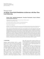
The block diagram of a typical delta modulator is shown in
Figure 1. Its operation is based on 1-bit quantization at each
sampling instant of the error signal e(n) that results from the
input sample x(n) after subtracting its predicted value y(n),
that is, e(n)
= x(n) − y(n). The generated output signal L(n)
takes the values +1 or
−1 and consists of binary pulses which
are fed into an integrator in the feedback loop resulting in a
2 EURASIP Journal on Advances in Signal Processing
1
1 z
1
x(n)
+
e(n)
L(n)
y(n)
Input
Output
z
1
Figure 1: Block diagram of a typical delta modulator.
fixed step-size Δ increase or decrease of its previous output
y(n
− 1), so that
sgn
e(n)
=
sgn
x( n) − y(n)
=
L(n), (1a)
y(n)
= y(n − 1) + L(n)Δ. (1b)
In ADM systems, the step size of the employed quantizer is
varying according to a decided rule with respect to input sig-
nal. The general form of common instantaneous step-size
adaptation algorithms in ADM systems can be written as
Δ(n)
= M(n)Δ(n − 1), (2)
where Δ(n) is the step-size magnitude at time n with values
within a region [Δ
min
, Δ
max
]andM(n) is the corresponding
step-size multiplier defined according to a specific rule. For
example, in CFDM [1], M(n) depends on the present and
previous output bits L(n)andL(n
− 1) revealing a “mem-
ory” characteristic in step-size estimation at each sampling
instant, while in multibit ADM, M(n)canbeafunctionof
present and previous output codewords L
w
(n)andL
w
(n−1),
being the “memory” characteristic, [3, 4], as well as a func-
tion of the magnitude of the error signal e( n), that is, the
difference between the input sample x(n) and its predicted
value y(n), with respect to a specified threshold, [4, 5], be-
ing the “look-ahead” characteristic in step-size estimation,
respectively.
The 2-digit ADM system, [7, 8], follows the genera l rule
expressed by (2)whereM(n) depends on both the sign of
e(n)ande(n
− 1) (equivalently the present and previous out-
put codewords) and the magnitude of e(n), as expressed by
M(n)
=
⎧
⎪
⎪
⎪
⎪
⎪
⎨
⎪
⎪
⎪
⎪
⎪
⎩
N(n)β if
e(n)
≥
1
2
(β +1)N(n)Δ(n
− 1),
N(n) otherwise,
N(n)
β
if
e(n)
≤
1
2
1
β
+1
N(n)Δ(n − 1),
(3)
with β>1, and
N(n)
=
⎧
⎪
⎨
⎪
⎩
α if sgn
e(n)
=
sgn
e(n − 1)
,
1
α
if sgn
e(n)
=
sgn
e(n − 1)
,
(4)
where α>1.
It is clear that at each sampling instance n the step multi-
plier M(n) takes one of six in total values and, therefore, the
produced output codeword W(n) consists of a binary digit
L
1
(n) taking values 1 or −1 and a ternary digit L
2
(n) t aking
values 1, 0, or
−1. By considering that L
1
(n) describes the
sign of e(n) according to (1a), and L
2
(n) describes the re-
lation between M(n)andN(n), the adaptation rule for the
2-digit ADM can be written in a compact form as
Δ(n)
= α
L
1
(n)L
1
(n−1)
β
L
2
(n)
Δ(n − 1) (5)
with Δ
min
≤ Δ(n) ≤ Δ
max
and L
1
(n) = (1 or −1) and L
2
(n) =
(1, 0, or − 1) for every n. Following the above, the quantized
sample y(n), that is, the predicted value for the input sample
x( n), at each sampling instant will therefore be given by
y(n)
= y(n − 1) + L
1
(n)Δ(n)(6a)
with
L
1
(n) = sgn
e(n)
=
sgn
x( n) − y(n)
(6b)
and this value is to be recovered at the receiver output prior
filtering.
The 2-bit ADM system described by Aldajani, [9, 10],
generates output codewords consisting of two binary digits
which carry information about the sign of the error signal
e(n)
= x(n) − y(n) as well as its absolute value, so that the
step size is determined at each sampling period according to
the rule
Δ(n)
=
⎧
⎪
⎨
⎪
⎩
αΔ(n − 1) if
e(n)
> Δ(n − 1),
1
α
Δ(n − 1) otherwise,
(7a)
where α>1, and its sign by
L
1
(n) = sgn
e(n)
. (7b)
Denoting the two output binary digits as L
1
(n)andL
2
(n)
with values 1 or
−1, the step adaptation rule of the 2-bit
ADM system, following the general form given by (1), can
then be expressed as
Δ(n)
= α
L
2
(n)
Δ(n − 1) (8)
so that again
y(n)
= y(n − 1) + L
1
(n)Δ(n). (9)
3. THE PROPOSED NEW 2-BIT
ADAPTATION ALGORITHM
Based on the adaptation algorithm of the 2-digit ADM sys-
tem presented above, we now propose a modification that
eliminates the need of a ternary digit in the generated output
codeword at the expense of a slightly inferior SNR perfor-
mance. However, the resulting new 2-bit ADM maintains its
“memory” and “look-ahead” characteristics in step-size esti-
mation as well as its ability to offer high SNR values, reduced
overshoot, and fast response to input signal variations.
E. A. Prosalentis and G. S. Tombras 3
Following (2), (3), and (4), the new algorithm is based on
the replacement of (3)by
M(n)
=
⎧
⎪
⎪
⎪
⎨
⎪
⎪
⎪
⎩
N(n)β if
e(n)
≥
1
2
β +
1
β
N(n)Δ(n − 1),
N(n)
β
otherwise
(10)
with β>1.
According to this equation, at each sampling instant,
the absolute value of the error signal e(n)iscomparedtoa
threshold being in the middle of the distance between the
two possible step-size values, that is, N(n)Δ(n − 1)β and
N(n)Δ(n
−1)/β. Hence, similarly to the 2-digit ADM system,
the relation between M(n)andN(n) needs to be represented
at the encoder output by a second digit which, here, takes
only two values and, thus, it can be a binary digit L
2
(n)with
values 1 (e.g., amplitude +V) or
−1 (amplitude −V).
However, considering the 2-digit ADM system and its
ternary second output digit or, equivalently, the three possi-
ble values for M(n)givenby(3), the omitted third condition,
described by (10), is partly covered by introducing an addi-
tional memory function with respect to the second output
bit’s present and previous values, that is, L
2
(n)andL
2
(n − 1).
Hence,anewvariableγ(n)isdefinedas
γ(n)
=
⎧
⎨
⎩
γ if L
2
(n) = L
2
(n − 1) =−1,
1 otherwise,
(11)
where γ>1.
Considering (10)and(4), the step-size adaptation rule of
the new 2-bit ADM system is now written in the form
Δ(n)
= α
L
1
(n)L
1
(n−1)
β
L
2
(n)
γ(n)Δ(n − 1), (12)
where γ(n)isspecifiedby(11), and, again,
y(n)
= y(n − 1) + L
1
(n)Δ(n). (13)
Following the above, the generated 2-bit output code-
word conveys information about the sign and one out of
six possible values for the new step-size multiplier M
(n) =
M(n)γ(n) = Δ(n)/Δ( n − 1) to the appropriate demodula-
tor.ThesevaluesofM
(n) are shown in Ta ble 1 with respect
to the corresponding combinations of present and previous
output codewords of the proposed 2-bit ADM system. In ad-
dition, the values for constants α, β,andγ that appear in (11)
and (12)arechosenasfollows:
(i) α is set equal to the constant step-size multiplier—
the ratio of the modified step-size to the previous step
size—of CFDM [1, 2], widely known as P, since the
first-bit memory function described by (3) is identical
to its adaptation algorithm (1 <α
≤ 2),
(ii) β must be greater than α
2
, where the exponent 2 re-
flects the bit-rate relationship between the presented
system and CFDM (or LDM). Thus, if α is defined in
the region [1.1, 1.5], a reasonable choice for β will be
1.2 <β
≤ 2.5,
Table 1
L
1
(n − 1) L
2
(n − 1) L
1
(n)L
2
(n) M
(n)
1111αβ
111
−1 α/β
11
−11β/α
11
−1 −11/αβ
1
−111αβ
1
−11−1 αγ/β
1
−1 −11β/α
1
−1 −1 −1 γ/αβ
−1111β/α
−111−11/αβ
−11−11αβ
−11−1 −1 α/β
−1 −111β/α
−1 −11−1 γ/αβ
−1 −1 −11αβ
−1 −1 −1 −1 αγ/β
1
1 z
1
x(n)
γ(n)
L
2
(n 1)
e(n)
L
2
(n)
+
y(n)
Input
z
1
Δ(n)
Output
L
1
(n)
Adaptation
circuit
Adaptation
logic
circuit
Error
comparator
β
L
2
(n)
z
1
z
1
e(n)
z
1
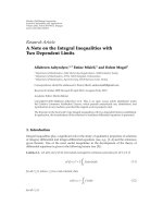
Figure 2: Block diagram of the proposed 2-bit ADM scheme.
(iii) γ<β, so that the step-size multipliers αγ/β and γ/αβ
(shown in Table 1) are smaller than α and 1/α,respec-
tively. This condition ensures the convergence of the
modulator.
The block diagram of the proposed 2-bit ADM system is
shown in Figure 2. It consists of a basic DM scheme that gen-
erates output bit L
1
(n) and a step-size Δ(n) estimation circuit
including the error comparator according to (10)whichpro-
duces output bit L
2
(n), and two memory adaptation modules
in order to specify γ(n)andΔ(n) according to (11)and(12),
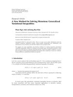
respectively. Figure 3 shows the input-output chara cteristic
of the error comparator which generates L
2
(n).
4 EURASIP Journal on Advances in Signal Processing
(1/β)N(n)Δ(n 1)
e(n)
L
2
(n)
1
0
1
βN(n)Δ(n
1)
(1/2)(β +1/β)N(n)Δ(n
1)
Figure 3: Input-output characteristic of the error comparator gen-
erating output bit L
2
(n).
10
5
0
5
10
10
5
0
5
10
10
5
0
5
10
10
5
0
5
10
Amplitude (V)
0.511.522.533.544.5
10
3
Time (s)
CFDM
2-bit ADM
2-digit ADM
Proposed
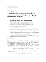
Figure 4: Bipolar returned-to-zero pulse response of the four sys-
tems for the same output baud.
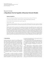
4. SIMULATION RESULTS
In this section, we present computer simulation results for
comparing the performance of the proposed 2-bit ADM sys-
tem to that of CFDM, 2-bit ADM, and 2-digit ADM.
At first, we use a bipolar return-to-zero rectangular in-
put pulse in order to compare the four systems in terms of
their pulse response and overshoot characteristics. All sys-
tems are considered to generate exactly the same baud at their
output, meaning that the sampling rate of the 2-bit ADM
and the proposed system operate at half the sampling rate
f
s
of CFDM, while the 2-digit ADM at 2.6 times lower rate
than f
s
[7, 8]. In addition, all systems assume the same ini-
tial step size. The results, shown in Figure 4,revealasub-
0
2
4
6
8
10
12
14
16
SNR (dB)
40 30 20 10 0 10 203040
Amplitude (dB)
CFDM
2-bit ADM
2-digit ADM
Proposed α
= 1.1 β = 1.9 γ = 1.5
Proposed α
= 1.1 β = 1.8 γ = 1.2
Figure 5: SNR values for different amplitudes of a speech input
signal for the same output bit rate (dynamic range of step size:
±20 dB).
stantially faster response of the proposed 2-bit ADM system
in comparison to the two other multidigit schemes, and re-
duced overshoot with faster settling time in comparison to
CFDM.
In a second comparison, we use an actual speech signal of
5 seconds duration sampled at 22050 Hz. The same sampling
rate is used for CFDM, while for the 2-bit ADM and the pro-
posed system, the sampling rate is 22050/2 Hz, and for the
2-digit ADM, 22050/2.6 Hz. We then choose the initial step-
size for all the systems under comparison to be the value of
the optimum step-size of a linear DM system, that is, the step
size that maximizes SNR for the particular speech signal. In
addition, we define two ranges of step size variations, being
±20 dB and ±30 dB with respect to the chosen initial step
size. Finally, we use two sets of values for the parameters α,
β,andγ of the proposed system: [α
= 1.1, β = 1.9, γ = 1.5]
and [α
= 1.1, β = 1.8, γ = 1.2], while for CFDM, we choose
α
= 1.1, for 2-bit ADM system α = 2, and for the 2-digit
system α
= 1.1andβ = 2α. All these values are considered
optimum for speech signals [1, 7, 8, 10].
The comparison is carried out in terms of the achieved
SNR for different amplitudes of the chosen input signal seg-
ment for the two dynamic ranges of step-size variation, as
mentioned above, and the obtained simulation results are
shown in Figures 5 and 6, respectively. In both figures, CFDM
offers smooth operation with respect to the obtained SNR
values over a range of input amplitudes that corresponds to
the range of step-size variations. Compared to the other sys-
tems, this smooth operation is achieved at the expense of
inferior SNR values. The best SNR values are achieved by
the 2-digit ADM at the expense of a slightly limited input
dynamic r ange, while the 2-bit system and the proposed new
one offer relative high SNR values maintaining an accept-
able high-input dynamic ra nge. However, the proposed new
2-bit ADM system appears to retain high SNR values in a
smoother manner than that of the 2-bit system. Thus, this
reveals a smooth and stable operation over a wide range of
input signal amplitudes for both sets of values for α, β,andγ.
E. A. Prosalentis and G. S. Tombras 5
0
2
4
6
8
10
12
14
16
SNR (dB)
40 30 20 10 0 10 203040
Amplitude (dB)
CFDM
2-bit ADM
2-digit ADM
Proposed α
= 1.1 β = 1.9 γ = 1.5
Proposed α
= 1.1 β = 1.8 γ = 1.2
Figure 6: SNR values for different amplitudes of a speech input
signal for the same output bit rate (dynamic range of step size:
±30 dB).
5. CONCLUSION
In this paper, we proposed a new 2-bit ADM system,
whose step-size adaptation algorithm is a result of modify-
ing the adaptation algorithm of a 2-digit ADM system as
described in Section 2. The employed quantizer generates
output codewords that consist of two bits. The first rep-
resents the sign of the difference between the input sam-
ple and its predicted—through the quantization process—
value and is used with respect to its previous value reveal-
ing a “memory” function in step-size estimation similar to
that of CFDM. The second bit is used with respect to its
previous value as well, in order to specify the one out of
six values for the step-size multiplier in a “look-ahead” ef-
fort to minimize the quantization error both locally and at
the corresponding demodulator. As computer simulation re-
sults have shown, the new system offers fast response, re-
duced overshoot, and high SNR values for a wide range of
input signal amplitude variations, when compared to other
similar ADM schemes, at the expense of some unavoidable
added complexity. Further more, the described adaptation al-
gorithm can be used in order to enhance the dynamic range
of other analog-to-digital conversion schemes and offer high
SNR performance and robustness in tracking highly varying
signals.
REFERENCES
[1] N. S. Jayant, “A daptive delta modulation with a one-bit mem-
ory,” Bell Systems Technical Journal, vol. 49, pp. 321–342, 1970.
[2] R. Steele, Delta Modulation Systems, Pentech Press, London,
UK, 1975.
[3] N. S. Jayant, “Adaptive quantization with a one-word mem-
ory,” Bell Systems Technical Journal, vol. 52, no. 7, pp. 1119–
1144, 1973.
[4] P. Cummiskey, N. S. Jayant, and J. L. Flanagan, “Adaptive
quantization in differential PCM coding of speech,” Bell Sys-
tems Technical Journal, vol. 52, no. 7, pp. 1105–1118, 1973.
[5] D. J. Goodman and A. Gersho, “Theory of an adaptive quan-
tizer,” IEEE Transactions on Communications,vol.22,no.8,pp.
1037–1045, 1974.
[6] F. T. Sakane and R. Steele, “Two-bit instantaneously adaptive
delta modulation for PCM encodin,” The Radio and Electronic
Engineer, vol. 48, pp. 187–197, 1978.
[7] G. S. Tombras, A study of methods to improve LDM and ADM
perfor mance, Ph.D. thesis, University of Thessaloniki, Thessa-
loniki, Greece, 1988.
[8] G. S. Tombras and C. A. Karybakas, “New adaptation algo-
rithm for a two-digit adaptive delta modulation system,” In-
ternational Journal of Electronics, vol. 68, no. 3, pp. 343–349,
1990.
[9] M. A. Aldajani and A. H. Sayed, “A stable adaptive structure
for delta modulation with improved performance,” in Proceed-
ings of IEEE International Conference on Acoustics, Speech and
Signal Processing (ICASSP ’01), vol. 4, pp. 2621–2624, Salt Lake
City, Utah, USA, May 2001.
[10] M. A. Aldajani and A. H. Sayed, “Stability and performance
analysis of an adaptive sigma-delta modulator,” IEEE Transac-
tions on Circuits and Systems II, vol. 48, no. 3, pp. 233–244,
2001.
E. A. Prosalentis was born in Athens,
Greece, in 1966. He received the B.S. degree
in physics and the M.S. degree in electronics
from the University of Athens, in 1989 and
1993, respectively. Since 1997, he has been a
Professor of electronics in post-compulsory
secondary education. From 2001 to 2004, he
was associated with the Department of Elec-
tronics in the Technological Educational In-
stitute (TEI) of Athens, where he was re-
sponsible for the laboratory course in radar and radio systems. He
is currently a Ph.D. candidate at the Laboratory of Electronics, De-
partment of Physics, University of Athens.
G. S. Tombras was born in Athens, Greece,
in 1956. He received the B.S. degree in
physics from Aristotelian University of
Thessaloniki, Greece, the M.S. degree in
electronics from University of Southamp-
ton, UK, and the Ph.D. degree from Aris-
totelian University of Thessaloniki, in 1979,
1981, and 1988, respectively. From 1981 to
1989, he was a Teaching and Research Assis-
tant and, from 1989 to 1991, he was a Lec-
turer at the Laboratory of Electronics, Physics Department, Aris-
totelian University of Thessaloniki. From 1990 to 1991, he was with
the Institute of Informatics and Telecommunications of the Na-
tional Center for Science Research “Demokritos,” Athens, Greece.
Since 1991, he has been with the Laboratory of Electronics, De-
partment of Physics, University of Athens, where he is currently
an Associate Professor of Electronics. His research interests include
mobile communications, analog and digital circuits and systems,
as well as instrumentation, measurements, and audio engineering.
Professor Tombras is the author of the textbook Introduction to
Electronics (in Greek) and has authored or coauthored more than
70 journal and conference papers and many technical reports.