Báo cáo hóa học: " Research Article An MPSoC-Based QAM Modulation Architecture with Run-Time Load-Balancing" pdf
Bạn đang xem bản rút gọn của tài liệu. Xem và tải ngay bản đầy đủ của tài liệu tại đây (1.35 MB, 15 trang )
Hindawi Publishing Corporation
EURASIP Journal on Embedded Systems
Volume 2011, Article ID 790265, 15 pages
doi:10.1155/2011/790265
Research Article
An MPSoC-Based QAM Modulation Architecture with Run-Time
Load-Balancing
Christos Ttofis,
1
Agathoklis Papadopoulos,
1
Theocharis Theocharides,
1
Maria K. Michael,
1
and Demosthenes Doumenis
2
1
KIOS Research Center, Depar tment of ECE, University of Cyprus, 1678 Nicosia, Cyprus
2
SignalGeneriX Ltd, 3504 Limassol, Cyprus
Correspondence should be addressed to Christos Ttofis, ttofi
Received 28 July 2010; Revised 8 January 2011; Accepted 15 January 2011
Academic Editor: Neil Bergmann
Copyright © 2011 Christos Ttofis et al. This is an open access article distributed under the Creative Commons Attribution License,
which permits unrestricted use, distribution, and reproduction in any medium, provided the original work is properly cited.
QAM is a widely used multilevel modulation technique, with a variety of applications in data radio communication systems. Most
existing implementations of QAM-based systems use high levels of modulation in order to meet the high data rate constraints of
emerging applications. This work presents the architecture of a highly parallel QAM modulator, using MPSoC-based design flow
and design methodology, which offers multirate modulation. The proposed MPSoC architecture is modular and provides dynamic
reconfiguration of the QAM utilizing on-chip interconnection networks, offering high data rates (more than 1 Gbps), even at low
modulation levels (16-QAM). Furthermore, the proposed QAM implementation integrates a hardware-based resource allocation
algorithm that can provide better throughput and fault tolerance, depending on the on-chip interconnection network congestion
and run-time faults. Preliminary results from this work have been published in the Proceedings of the 18th IEEE/IFIP International
Conference on VLSI and System-on-Chip (VLSI-SoC 2010). The current version of the work includes a detailed description of the
proposed system architecture, extends the results significantly using more test cases, and investigates the impact of various design
parameters. Furthermore, this work investigates the use of the hardware resource allocation algorithm as a graceful degra dation
mechanism, providing simulation results about the performance of the QAM in the presence of faulty components.
1. Introduction
Quadrature Amplitude Modulation (QAM) is a popular
modulation scheme, widely used in various communication
protocols such as Wi-Fi and Digital Video Broadcasting
(DVB) [1]. The architecture of a digital QAM modula-
tor/demodulator is typically constrained by several, often
conflicting, requirements. Such requirements may include
demanding throughput, high immunity to noise, flexibility
for various communication standards, and low on-chip
power. The majority of existing QAM implementations
follow a sequential implementation approach and rely on
high modulation levels in order to meet the emerging
high data rate constraints [1–5]. These techniques, however,
are vulnerable to noise at a given transmission power,
which reduces the reliable communication distance [1].
The problem is addressed by increasing the number of
modulators in a system, through emerging Software-Defined
Radio (SDR) systems, which are mapped on MPSoCs in an
effort to boost parallelism [6, 7]. These works, however, treat
the QAM modulator as an individual system task, whereas
it is a task that can further be optimized and designed with
further parallelism in order to achieve high data rates, even
at low modulation levels.
Designing the QAM modulator in a parallel manner can
be beneficial in many ways. Firstly, the resulting parallel
streams (modulated) can be combined at the output, result-
ing in a system whose majority of logic runs at lower clock
frequencies, while allowing for high throughput even at low
modulation levels. This is particularly important as lower
modulation levels are less susceptible to multipath distortion,
provide power-efficiency and achieve low bit error rate (BER)
[1, 8]. Furthermore, a parallel modulation architecture can
benefit multiple-input multiple-output (MIMO) commu-
nication systems, where information is sent and received
over two or more antennas often shared among many users
2 EURASIP Journal on Embedded Systems
[9, 10]. Using multiple antennas at both transmitter
and receiver offers significant capacity enhancement on
many modern applications, including IEEE 802.11n, 3GPP
LTE, and mobile WiMAX systems, providing increased
throughput at the same channel bandwidth and trans-
mit power [9, 10].Inordertoachievethebenefitof
MIMO systems, appropriate design aspects on the mod-
ulation and demodulation architectures have to be taken
into consideration. It is obvious that transmitter architec-
tures with multiple output ports, and the more compli-
cated receiver architectures with multiple input ports, are
mainly required. However, the demodulation architecture
is beyond the scope of this work and is part of future
work.
This work presents an MPSoC implementation of
the QAM modulator that can provide a modular and
reconfigurable architecture to facilitate integration of the
different processing units involved in QAM modulation.
The work attempts to investigate how the performance of a
sequential QAM modulator can be improved, by exploiting
parallelism in two forms: first by developing a simple,
pipelined version of the conventional QAM modulator, and
second, by using design methodologies employed in present-
day MPSoCs in order to map multiple QAM modulators
on an underlying MPSoC interconnected via packet-based
network-on-chip (NoC). Furthermore, this work presents a
hardware-based resource allocation algorithm, enabling the
system to further gain performance through dynamic load
balancing. The resource allocation algor ithm can also act
as a graceful degradation mechanism, limiting the influence
of run-time faults on the average system throughput.
Additionally, the proposed MPSoC-based system can adopt
variable data rates and protocols simultaneously, taking
advantage of resource sharing mechanisms. The proposed
system architecture was simulated using a high-level sim-
ulator and implemented/evaluated on an FPGA platform.
Moreover, although this work currently targets QAM-based
modulation scenarios, the methodology and reconfigu-
ration mechanisms can target QAM-based demodulation
scenarios as well. However, the design and implementa-
tion of an MPSoC-based demodulator was left as future
work.
While an MPSoC implementation of the QAM mod-
ulator is beneficial in terms of throughput, there are
overheads associated with the on-chip network. As such, the
MPSoC-based modulator was compared to a straightforward
implementation featuring multiple QAM modulators, in
an effort to identify the conditions that favor the MPSoC
implementation. Comparison was carried out under variable
incoming rates, system configurations and fault conditions,
and simulation results showed on average double throughput
rates during normal operation and
∼25% less throughput
degradation at the presence of faulty components, at the
cost of approximately 35% more area, obtained from an
FPGA implementation and synthesis results. The hardware
overheads, which stem from the NoC and the resource
allocation algorithm, are well within the typical values for
NoC-based systems [11, 12] and are adequately balanced by
the high throughput rates obtained.
The rest of this paper is organized as follows. Section 2
briefly presents conventional QAM modulation and dis-
cusses previous related work. Section 3 presents the proposed
QAM modulator system and the hardware-based allocation
algorithm. Section 4 provides experimental results in terms
of throughput and hardware requirements, and Section 5
concludes the paper.
2. Background-Related Work
2.1. QAM Modulator Background. A QAM modulator trans-
mits data by changing the amplitude of two carrier waves
(mostly sinusoidal), which have the same frequency, but
are out of phase by 90
◦
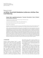
[1, 13, 14]. A block diagram of a
conventional QAM modulator is shown in Figure 1. Input
bit streams are grouped in m-tuples, where m
= log
2
(n),
and n is the level of modulation. The Symbol Mapper splits
input sequences into symbols consisting of I (in-phase) and
Q (quadrature) words and maps each word into a coded
number, typically following Gray encoding [1]. For example,
a 16-QAM modulator maps each I and Q word into four
(m
= 4 bits per symbol) different values from the set
A
={−3, −1, 1, 3}. Gray encoding ensures that consecutive
symbols differ by only one bit and is preferred for power
consumption purposes and for practical demodulation.
The sine and cosine intermediate frequency (IF) signals
are generated by a Numerically Controlled Oscillator (NCO),
using lookup tables (LUTs) to store the samples of the
sinusoidal signals [15]. Alternatively, the NCO can contain
only one LUT for storing the sine values and use a 90
◦
phase offset ( accessing the LUT with a sample offset) to
generate the cosine values. The NCO receives as inputs the
system clock, f
s
, and the phase increment, M. The phase
increment represents the amount of phase change in the
output signal during each clock period and is added to
the phase accumulator every system clock period. Based on
the values of f
s
, M, and also on the number of entries in
the LUTs, 2
N
, the frequency of the carrier wave signal is
computed as in (1). The output frequency must satisfy the
Nyquist theorem, and thus, f
c
must be less than or equal to
f
s
/2[1]:
f
c
= M ·
f
s
2
N
. (1)
The phase accumulator addresses the sine/cosine LUTs,
which convert phase information into values of the
sine/cosine wave (amplitude information). The outputs of
the sine and cosine LUTs are then multiplied by the words
I and Q, which are both filtered by FIR filters before
being multiplied to the NCO outputs. Typically, Raised
Cosine (RC) or Root-Raised Cosine (RRC) filters are used.
Filtering is necessary to counter many problems such as the
Inter Symbol Interference (ISI) [16], or to pulse shape the
rectangular I, Q pulses to sinc pulses, which occupy a lower
channel bandwidth [16].
The products are finally added in order to generate a
modulated signal of the form of (2), where I and Q are
the in-phase and quadrature words, respectively, and f
c
is
EURASIP Journal on Embedded Systems 3
the carrier frequency. During a symbol per iod, the QAM
signal is a phase-shifted sinusoid with its amplitude equal to
I
2
+ Q
2
, and the phase difference from a reference carrier
cos(2πf
c
t)istan
−1
(Q/I). This signal feeds a D/A converter
and eventually drives the RF antenna:
s
(
t
)
= I · cos
2πf
c
t
+ Q · sin
2πf
c
t
. (2)
2.2. Related Work. Most of the existing hardware imple-
mentations involving QAM modulation/demodulation fol-
low a sequential approach and simply consider the QAM
as an individual module. There has been limited design
exploration, and most works allow limited reconfiguration,
offering inadequate data rates when using low modulation
levels [2–5]. The latter has been addressed through emerging
SDR implementations mapped on MPSoCs, that also treat
the QAM modulation as an individual system task, integrated
as part of the system, rather than focusing on optimizing
the performance of the modulator [6, 7]. Works in [2,
3] use a specific modulation type; they can, however, be
extended to use higher modulation levels in order to increase
the resulting data rate. Higher modulation levels, though,
involve more divisions of both amplitude and phase and can
potentially introduce decoding errors at the receiver, as the
symbols are very close together (for a given transmission
power level) and one level of amplitude may be confused
(due to the effect of noise) with a higher level, thus, distorting
the received signal [8]. In order to avoid this, it is necessary
to allow for wide margins, and this can be done by increasing
the available amplitude r ange through power amplification
of the RF signal at the transmitter (to effectively spread the
symbols out more); otherwise, data bits may be decoded
incorrectly at the receiver, resulting in increased bit error
rate (BER) [1, 8]. However, increasing the amplitude range
will operate the RF amplifiers well within their nonlinear
(compression) region causing distortion. Alternative QAM
implementations try to avoid the use of multipliers and
sine/cosine memories, by using the CORDIC algorithm [4,
5], however, still follow a sequential approach.
Software-based solutions lie in designing SDR systems
mapped on general purpose processors and/or digital signal
processors (DSPs), and the QAM modulator is usually
considered as a system task, to be scheduled on an available
processing unit. Works in [6, 7] utilize the MPSoC design
methodology to implement SDR systems, treating the modu-
lator as an individual system task. Results in [6] show that the
problem with this approach is that several competing tasks
running in parallel with QAM may hurt the performance
of the modulation, making this approach inadequate for
demanding wireless communications in terms of throughput
and energy efficiency. Another particular issue, raised in [6],
is the efficiency of the allocation algorithm. The allocation
algorithm is implemented on a processor, which makes
allocation slow. Moreover, the policies used to allocate
tasks (random allocation and distance-based allocation) to
processors may lead to on-chip contention and unbalanced
loads at each processor, since the utilization of each processor
is not taken into account. In [7], a hardware unit called
CoreManager for run-time scheduling of tasks is used,
which aims in sp eeding up the allocation algorithm. The
conclusions stemming from [7] motivate the use of exporting
more tasks such as reconfiguration and resource allocation in
hardware rather than using software running on dedicated
CPUs, in an effort to reduce power consumption and
improve the flexibility of the system.
This work presents a reconfigurable QAM modulator
using MPSoC design methodologies and an on-chip net-
work, with an integrated hardware resource allocation mech-
anism for dynamic reconfiguration. The allocation algorithm
takes into consideration not only the distance between
partitioned blocks (hop count) but also the utilization of
each block, in attempt to make the proposed MPSoC-
based QAM modulator able to achieve robust performance
under different incoming rates of data streams and different
modulation levels. Moreover, the allocation algorithm inher-
ently acts as a graceful degr adation mechanism, limiting
the influence of run-time faults on the average system
throughput.
3. Proposed System Architecture
3.1. Pipelined QAM Modulator. A first attempt to improve
the perfor mance can be done by increasing the parallelism of
the conventional QAM, through pipelining. The data rate of
a conventional QAM modulator depends on the frequency of
the carrier wave, Mf
s
/2
N
. This frequency is 2
N
/M slower than
that of the system clock. The structure of a pipelined QAM
modulator consists of 2
N
/M stages, and thus, the throughput
can be 2
N
/M times higher to that of the conventional
modulator. The conventional modulator receives symbols on
each cycle of the carrier wave and achieves a data rate given by
(3), whereas the pipelined implementation receives symbols
on each system clock cycle and achieves a data rate given by
(4). It must be noted that the bit rate given by (3)and(4)
represents the rate at which data can be processed by the
modulation architecture, not the rate at which information
can be transmitted over a communication channel. The data
transmission rate in bits per second over a channel is limited
by the available channel bandwidth (BW) and the ratio of
the signal power to the noise power corrupting the signal
(SNR). The theoretical channel capacity limits were defined
by the Shannon-Hartley theorem [17], illustrated in (5),
and can be extended to approximate the capacity of MIMO
communication channels by multiplying (5) by the number
of spatial streams (number of antennas). A transmission
over a communication channel can be accomplished without
error in the presence of noise if the information rate given by
(3)and(4) is smaller than or equal to the channel capacity
(Bit rate
≤ Channel capacity):
bit rate
conv.
= log
2
(
n
)
· M ·
f
s
2
N
,
(3)
bit rate
pipelined
= f
s
· log
2
(
n
)
,(4)
Channel capacity
= BW · log
2
(
1+SNR
)
.
(5)
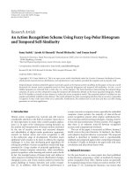
Figure 2 illustrates the concept of the pipelined QAM
modulator. Each stage of the pipeline consists of four
4 EURASIP Journal on Embedded Systems
Delta
phase
REG. M
PHASE
REG.
cos(2πf
c
)
LUT
sin(2πf
c
)
LUT
FIR
filter
Phase accumulator
m
= log
2
(n)
I cos(2πf
c
t)+Q sin(2πf
c
t)
FIR
filter
Symbol
mapper
D/A
RF
antenna
Power
AMP
NCO
M
Figure 1: Conventional QAM modulator [5].
registers, two multipliers and one adder. Sine and cosine
registers are used to store the values of the sine and cosine
LUTs for a specific phase angle step, while I and Q registers
store the filtered versions of the I and Q words, respectively.
Thevaluesofthesine and cosine registers during a particular
clock cycle will be the data for the next pipeline stage sine and
cosine registers during the following clock cycle. The values of
the I and Q registers, on the other hand, are not transferred
from the previous pipeline stage but instead are fed from two
1to2
N
/M demultiplexers, whose control logic is generated
from a 2
N
/M counter. It is necessary, therefore, that the
values of I and Q registers remain constant for 2
N
/M cycles.
This is necessary because each I, Q word must be multiplied
by all values of the sine and cosine signals, respectively.
In the proposed QAM modulation system, the LUTs have
a constant number of 1024 entries. The value of M can
vary during operation, as shown in Figure 2. The maximum
number of pipeline stages is determined by the overall
hardware budget. In this work, we used 16 pipeline stages,
hence the value of M canbegreaterthanorequalto64.
3.2. MPSoC-Based QAM Modulator. Next, we used MPSoC
design methodologies to map the QAM modulator onto an
MPSoC architecture, which uses an on-chip, packet-based
NoC. This allows a modular, “plug-and-play” approach
that permits the integration of heterogeneous processing
elements, in an attempt to create a reconfigurable QAM
modulator. By partitioning the QAM modulator into differ-
ent stand-alone tasks mapped on Processing Elements (PEs),
we construct a set of stand-alone basic components necessary
for QAM modulation. This set includes a Stream-IN PE, a
Symbol Mapper PE, an FIR PE, and a QAM PE. Multiple
instances of these components can then be used to build
a variety of highly parallel and flexible QAM modulation
architectures.
Figure 3 illustrates an example system configuration that
uses a 4
× 4 2D-mesh on-chip network. The challenges
involved in designing such system lie in designing the
appropriate network interface (NI) hardware, that is attached
to each PE and is responsible for interfacing the PE with
the underlying interconnect backbone. The NI also contains
the majority of the necessary logic that enables the system
to dynamically reconfigure itself through the hardware
implemented allocation algorithm. Although we target QAM
modulation, some of the stand-alone components are com-
mon in many other radio standards, enabling designers to
create platforms that can support multiple radio standards,
and to increase efficiency and flexibility of designs by sharing
resources.
The Stream-IN PEs receive input data from the I/O
ports and dispatch data to the Symbol Mapper PEs. The
NIs of the Stream-IN PEs assemble input data streams in
packets, which contain also the modulation level n and the
phase increment M, given as input parameters. By utilizing
multiple Stream-IN PEs, the proposed architecture allows
multiple transmitters to send data at different data rates and
carrier frequencies. The packets are then sent to one of the
possible Symbol Mapper PEs, to be split into symbols of I and
Q words. The Symbol Mapper PEs are designed to support
16, 64, 256, 1024, and 4096 modulation levels. I and Q words
are then created and packetized in the Symbol Mapper NIs
and transmitted to the corresponding FIR PEs, where they
are pulse shaped. The proposed work implements different
forms of FIR filters such as transpose filters, polyphase filters
and filters with oversampling. The filtered data is next sent
to QAM PEs (pipelined versions). The modulated data from
each QAM PE are finally sent to a D/A converter, before
driving an RF antenna.
The proposed modulator can be used in multiple input
and multiple output (MIMO) communication systems,
where the receiver needs to rearrange the data in the correct
order. Such a scenario involves multiple RF antennas at the
output (used in various broadcasting schemes [9, 10]) and
multiple RF a ntennas at the input (receiver). The scope of
MIMO systems and data rearrangement is beyond this paper
however; we refer interested readers to [ 9, 10]. Alternatively,
the resulting parallel streams can be combined at the output
resulting in a system whose majority of logic runs at lower
clock f requencies, while achieving high throughput.
Under uniform input streams (i.e., all inputs receive
the same data rate), each source PE has a predetermined
destination PE with which it communicates, and the system
functions as multiple pipelined QAM modulators. In the
probable case, however, that the incoming data stream rate
EURASIP Journal on Embedded Systems 5
sin
LUT
cos
LUT
Reg.
Q
1to
2
N
/M
demux
1to
2
N
/M
demux
Symbol
mapper
FIR
FIR
0to2
N
/M − 1
counter
Stage 1
Stage 2
NCO
Reg.
cos
Reg.
I
Reg.
sin
Reg.
Q
Reg.
cos
Reg.
I
Reg.
sin
Reg.
Q
Reg.
cos
Reg.
I
Reg.
sin
Stage 2
N
/M
···
···
Phase
acc.
Figure 2: Pipelined QAM modulator.
at one (or possibly more) input port is much higher than
the incoming data stream rate of the other input ports, the
MPSoC-based modulator allows inherent NoC techniques
such as resource allocation stemming from the use of the
on-chip network, to divert data streams to less active PEs,
and improve the overall throughput of the system. A source
PE can select its possible destination PEs from a set of
alternative, but identical in operation, PEs in the system,
rather than always communicating with its predetermined
destination PE. This is facilitated by integrating a dynamic
allocation algorithm inside the NIs of each PE called Network
Interface Resource Allocation (NIRA), a contribution of this
paper. The NIRA algorithm chooses the next destination PE
and is described in the following subsection.
There are two possible types of packets that can travel
across the on-chip network at any given time: data packets
and control packets. Data packets contain data streams,
symbols, filtered data, or modulated data, based on the
type of the source PE. Control packets, on the other hand,
contain the information needed by NIRA (free slots and
hop count information). As such, control packets precede
data packets; hence we utilize Virtual Channels (VCs) in
the underlying on-chip interconnect to provide priority to
the control packets. Control packets can then be forwarded
to the appropriate output port of the router as quickly as
possible, reducing the latency of control packets. The design
of each NI is parameterized and may be adjusted for different
kind of PEs; a basic architecture is shown in Figure 4 and
includes four FIFO queues and four FSMs controlling the
overall operation.
3.3. NIRA Resource Allocation Algorithm. Theresourceallo-
cation algorithm proposed in this work relies on a market-
based control technique [18]. This technique proposes the
6 EURASIP Journal on Embedded Systems
RF
antenna
RF
antenna
RF
antenna
RF
antenna
D/A
D/A
D/A
D/A
S
S
Stream-IN PE
M
M
Symbol Mapper PE
F
F
FIR PE
Q
Q
S
M FQ
S
M FQ
S
M FQ
QAM PE
NI NI NI NI
NI NI NI NI
NI NI NI NI
NI NI NI NI
R (0, 3)
R (0, 2)
R (0, 1)
R (0, 0)
R (1, 3)
R (1, 2)
R (1, 1)
R (1, 0)
R (2, 3)
R (2, 2)
R (2, 1)
R (2, 0)
R (3, 3)
R (3, 2)
R (3, 1)
R (3, 0)
Figure 3: An example of the proposed QAM system architecture.
interaction of local agents, which we call NIRA (Network
Interface Resource Allocation) agents, through which a
coherent global behavior is achieved [19]. A simple trading
mechanism is used between those local agents, in order
to meet the required global objectives. In our case, the
local agents are autonomous identical hardware distributed
across the NIs of the PEs. The hardware agents exchange
minimal data between NIs, to dynamically adjust the
dataflow between PEs, in an effort to achieve better overall
performance through load balancing.
This global, dynamic, and physically distributed resource
allocation algorithm ensures low per-hop latency under
no-loaded network conditions and manageable growth in
latency under loaded network conditions. The agent hard-
ware monitors the PE load conditions and network hop
count between PEs, and uses these as parameters based on
which the algorithm dynamically finds a route between each
possible pair of communicating nodes. The a lgorithm can be
applied in other MPSoC-based architectures with inherent
redundancy due to presence of several identical components
in an MPSoC.
TheproposedNIRAhardwareagentshaveidentical
structure and functionality and are distributed among the
various PEs, since they are part of every NI as shown in
Figure 4. NIRA is instantiated with a list of the addresses of
its possible s ource PEs and stores the list in its Send Unit
Register File (SURF). It also stores the hop count distances
between its host PE and each of its possible source PEs (i.e.,
PEs that send QAM data to that particular PE). Since the
mapping of PEs and their addresses is known at design
time, SURF can be loaded at design time for all the NIRA
instances.
The NIRA agent of each destination PE (which receives
data from the source PE) broadcasts a control packet during
specified time intervals T to the NIs of all PEs listed in
its SURF (i.e., its potential source PEs), indicating its host
NI load condition (free slots of FIFO1) and hop count
distance. While the hop count distance is static and known
at design time, source PEs can potentially receive control
packets out of order f rom destination PEs and, thus, would be
necessary for them to identify the destination PE’s hop count
through a search inside their own SURF. This would require
a context-addressable memory search and would expand the
hardware logic of each sender PE’s NIRA. Since one of our
objectives is scalability, we integrated the hop count inside
each destination PE’s packet. The source PE polls its host NI
for incoming control packets, which are stored in an internal
FIFO queue. During each interval T, when the source PE
receives the first control packet, a second timer is activated
for a specified number of clock cycles, W. When this timer
expires, the polling is halted and a heuristic algorithm based
on the received conditions is run, in order to decide the
next destination PE. In the case where a control packet is
not received from a source PE in the specified time interval
W, this PE is not included in the algorithm. This is a key
feature of the proposed MPSoC-based QAM modulator; at
extremely loa ded conditions, it attempts to maintain a stable
data rate by finding alternative PEs which are less busy.
Figure 5 shows an example of communicating PEs, which
interchange data and control packets.
The heart of each NIRA agent is a heuristic algorithm
based on which the destination PE is decided. The decision
is based on the fitness values of all possible destination PEs.
The fitness function chosen is simple; however, it is efficient
EURASIP Journal on Embedded Systems 7
Hop count
Next dest.
FIFO
Receive
unit
Control
logic
Clock
Reset
Timing
parameters
signal
generator
Reg file
Send
unit
Logic
Computation unit
Source
Destination
to NI
from NI
Control packet
NIRA
NIRA
DataRdy
Slots
Slots
Data in
Data
Out
Dest
To/from PE
FSM1
FSM2
FSM3
FSM4
FIFO1
FIFO2
From/to
router
PE port
FIFO3
Demux
1to2
Network interface
Figure 4: Network Interface with NIRA agent structure.
in terms of hardware resources and operational frequency.
The fitness value for each destination PE is a weighted
combination of the PE’s lo ad condition S(P
i
) and hop count
distance H(P
i
)metrics,asgivenby(6):
F
(
P
i
)
= 2
L
· S
(
P
i
)
− 2
K
· H
(
P
i
)
. (6)
Here, L and K are registered weight parameters which
can be adjusted to provide an accurate fitness function for
some possible network topology and mapping of PEs. The
weights on S() and H() are chosen to be powers of 2,
in order to reduce the logic required for calculating F(),
as the multiplication is reduced to simple shift operations.
During the computation of fitness values for every PE
in the NIRA agent’s internal FIFO, the maximum fitness
is held in an accumulator along its corresponding PE
address. Computation ends when the agent’s internal queue
becomes empty. The address value in the accumulator is the
destination for the next time period T and the solution of
(7), which satisfies the fitness function:
F
(
Next Destination
nT
)
= Max
F
(
P
i
)
,
∀P
i
∃ FIFO
(n−1)T
.
(7)
While NIRA is dynamically executed at run-time, it is
still important to initially map the processing elements of
the QAM system on the MPSoC, in such a way that satisfies
the expected operation of the QAM. This can be done by
mapping algorithms, such as the ones proposed in [20, 21].
After the initial placement of PEs into the network, the
decision about the destination PE for a source PE is made
by the NIRA algorithm. NIRA is particularly useful in cases
of network congestion that is mainly caused by two factors:
the incoming rate of data at Stream-IN PEs and the level of
modulation at Symbol Mapper PEs.
We next provide an example that illustrates the efficiency
of NIRA under a congestion scenario, which is created when
using different modulation levels at Symbol Mapper PEs.
Consider the architecture shown in Figure 3 and assume that
the Symbol Mapper PE at location (1,1) uses a modulation
level of 16, while the remaining Symbol Mapper PEs use
a modulation level of 256. When the incoming rate of
data at Stream-IN PEs is constant (assume 32 bits/cycle),
congestion can be created at the link between router (0,1)
and router (1,1). This is because the Symbol Mapper PE at
(1,1) splits each 32-bit input into more symbols (8 symbols
for 16-QAM compared to 4 symbols for 256-QAM). In this
case, the incoming rate of streams at St ream-IN PE (0,1)
could be lowered to match the rate at which the data is
processed by the Symbol Mapper PE (1,1) in order not to
lose data. However, our solution to this problem is not to
lower the incoming rate, but to divert data from Stream-IN
PE (0,1) to the less active Symbol Mapper PEs (1,0), (1,2), or
(1,3). This is possible through the integration of the NIRA
allocation algorithm inside the NIs of the PEs. When the
NI of the Stream-IN PE (0,1) receives the load condition
of all possible destination PEs (Symbol Mapper PEs), NIRA
algorithm is run to decide the next destination Symbol
Mapper PE. The algorithm takes into consideration the
received load conditions as well as the hop count distances
between Stream-IN PE (0,1) and the Symbol Mapper PEs
and solves (6)and(7) to select the next destination PE. In
this example, since the ra te of Stream-IN PEs (0,0), (0,2),
and (0,3) is equal, the utilization of Symbol Mapper PEs
(1,0), (1,2), and (1,3) will almost be equal, and therefore, the
next Symbol Mapper PE for the Stream-IN PE (0,1) will be
selected according to the hop count distance. Symbol Mapper
PEs (1,0) and (1,2) are more likely to be selected since they
are closer to the Stream-IN PE (0,1).
Besides dynamic allocation and reconfiguration, NIRA
algorithm offers another significant benefit to the MPSoC-
based QAM modulator. Given its operational properties, the
8 EURASIP Journal on Embedded Systems
D3
S3
At time nTInterval [(n
− 1)T, nT]
Source PE S3 forwards
data packets to its
destination PE D3
Interval [nT,(n+1)T]
NIRA assigns a new
destination PE D2 to
source PE
S3
S1
S2
S3
S4
D3
D2
S3
Each destination PE Di
broadcasts control information to
all possible source PEs S1–S4
Figure 5: Communicating PEs, interchanging data and control packets.
algorithm can be used as a graceful degradation mechanism,
limiting the influence of potential PE failures on the average
system throughput. Graceful degr adation in a system with
multiple instances of the same type of PEs is easy to accom-
plish, since a new configuration can be selected by NIRA
algorithm in the presence of one or more faulty PEs. The new
configuration must be selected in such a way as to obtain
satisfactory functionality using the remaining system PEs,
resulting in a system that still functions, albeit with lower
overall utility and throughput. As already said, once NIRA
algorithm runs, a particular configuration is established. In
the case of a PE failure, the absence of a control packet
from this particular PE will trigger NIRA to detect the fault.
A system reconfiguration will then be performed and the
faulty PE will be excluded from the new configuration, since
NIRA will run without taking into account the faulty PE.
In this way, the network traffic will bypass the faulty PE,
and the QAM modulator will continue its operation, while
NIRA’s load balancing attitude helps throughput degradation
to be kept at a minimum. Figure 6 illustrates an example
scenario where NIRA algorithm reorganizes the network at
the presence of a fault.
4. Experimental Results
4.1. Ex perimental Platform and Methodology. The perfor-
mance of the proposed QAM communication system was
evaluated using an in-house, cycle-accurate, on-chip net-
work and MPSoC simulator [22, 23]. The simulator was con-
figured to meet the targeted QAM modulation architecture
and the behavior of each QAM component. The NIRA agents
were also integrated. The individual components of the
proposed system, as well as the conventional and pipelined
QAM modulators, were implemented on a Xilinx Virtex-5
LX110T FPGA in order to derive comparative area results.
We first explored the benefits of the pipelined QAM
modulator, discussed in Section 3.1,overaconventional
QAM approach. We next evaluated the performance of the
proposed MPSoC-based modulator (Section 3.2)interms
of throughput (Mbps), using the configuration parameters
shown in Table 1. Given that the majority of existing works
lie on sequential QAM modulators, or the QAM is inside
a complete SDR system, and there is limited information
available that can be used as a comparison metric, compari-
son of the proposed MPSoC-based modulator with existing
works is impractical. The major issue is the impact of the
NoC and the NIRA algorithm on the performance of the
system and their associated overheads. As such, the proposed
system was compared against an equivalent system consisting
of multiple pipelined QAM instances, in order to investigate
the conditions where the MPSoC-based system outperforms
the non-reconfigurable system and v ice versa.
We evaluated the targeted QAM architectures using
different incoming rates of data streams at Stream-IN
PEs, in order to compare the architectures in terms of
performance (throughput). For each different data stream,
we also explored the impact of NIRA parameters L and K
on the overall system performance, by varying their values
(given that 2
L
+2
K
= 1) and determining the values that
yielded the best performance. The exploration of 2
L
and 2
K
parameters was carried out using floating point values during
simulation but was rounded to the nearest power of 2 for
hardware mapping purposes.
Lastly, we studied the impact of NIRA as a graceful
degradation mechanism, by r a ndomly creating fault condi-
tions inside the QAM, where a number of PEs experience
failures. Again, we compared the MPSoC-based architecture
(with NIRA) to its e quivalent system that integrates multiple
pipelined QAM instances. We measured the average through-
put of both architectures and observed their behavior under
different fault conditions and fault injection rates.
4.2. Performance Results. We first obtain the per formance
simulation results, using varied modulation levels, that run
across the sequential and the pipelined QAM modulators
(Figures 1 and 2), in order to a scertain the performance
advantages of the pipelined architecture. The results are given
in Table 2. As expected, the pipelined approach offers a
significant performance improvement over the sequential
approach. Next, we compare the performance of the MPSoC
implementation to an equivalent pipelined architecture.
Both architectures receive 4 input streams as input, as
describedinTable1, with 4 Stream-IN PEs. To compare the
EURASIP Journal on Embedded Systems 9
D1
D3
D2S
D4
D1
D3
D2
D4
D1
D3
D4
SS
Destination PE D2 fails cycles pass after (n +1)T
Source PE S takes into
account four possible
destination PEs D1–D4
On next W expiration,
no control packet
will be sent to source S
W cycles pass after nT W
Source PE S takes into
account three possible
destination PEs D1, D3 and D4
Figure 6: Example illustrating NIRA’s fault-tolerant behavior.
400
600
800
1000
1200
1400
1600
Case D.1
Case D.2
Case D.3
Case D.4
Case R.1
Case R.2
Case R.3
Case R.4
Case R.5
Deterministic Random
Throughput (Mbps)
Multiple pipeline instances w/o NIRA
MPSoC w/NIRA (optimal parameters per case)
(a)
Case D.1
Case D.2
Case D.3
Case D.4
Case R.1
Case R.2
Case R.3
Case R.4
Case R.5
Deterministic Random
Multiple pipeline instances w/o NIRA
MPSoC w/NIRA (optimal parameters per case)
(b)
Figure 7: Performance comparison per case: (a) throughput and (b) speedup gained.
two implementations, we constructed four different deter-
ministic input streams, labeled Case D.1 to Case D.4, as well
as five different random input streams, labeled Case R.1 to
Case R.5. Each case was constructed by varying the input data
rate at each St ream-IN PE. Furthermore, we provide high-
speed input streams at data rates exceeding the maximum
bandwidth of one modulator instance (pipelined version).
Each case, therefore, aims in creating varied network loads in
different locations in the network, in attempt to force NIRA
to perform load balancing, directing traffic from highly
loaded PEs to less- or non-loaded PEs. The different cases are
briefly described in Table 3. It must be noted that the w idth
of each input data stream is equal to the width of the on-
chip network links (32 bits). As such, the constructed cases
are expressed according to the expected number of cycles
required to receive a 32-bit data stream. While the number
of clock cycles between successive arrivals at Stream-IN PEs
is constant for the deterministic cases, the stream arrivals for
the random cases have been modeled as independent Poisson
processes, and thus, their interarrival times are exponentially
distributed with mean μ [24].
A comparison of the performance between the 4
× 4
MPSoC-based system (parameters shown in Table 1)and
its equivalent multi-pipelined system is shown in Figure 7
for all example c ases (Case D.1 to Case D.4 and Case R.1
to Case R.5). The obtained throughput results were taken
for a period of 10
6
clock cycles, using the NIRA parameters
2
L
and 2
K
, which were obtained through simulation and
were optimal for each example case. The T parameter was
also set to the optimal value for each case, and W was
set to 10 cycles (both parameters were determined from
NoC simulation). As can be seen, the four parallel-pipelined
QAM modulators outperform the MPSoC case only in Case
D.1 and Case R.5, where all inputs transmit data at the
same rate. This was obviously anticipated. However, the
drop in the performance is extremely low (less than
∼1%)
when comparing the two, due to mainly NoC delays, as
the system basically operates as four independent QAM
pipelines, processing individual streams. In the other cases,
however, the MPSoC-based system outperforms the multi-
pipelined system approximately twice on average, as the
reconfigurability of the network, along with the NIRA
10 EURASIP Journal on Embedded Systems
Table 1: MPSoC-based system configuration.
QAM parameters MPSoC and NoC parameters
Modulation level 16 Topology 2D-mesh
Phase increment
− M 128 Network size 4 × 4
No. of LUT entries
− 2
N
1024 Routing algorithm Static XY
Carrier frequency 12.5 MHz No. of VCs 3
No. of Stream-IN PEs 4 Switching mode Wormhole
No. of S. Mapper PEs 4 Link data width 32 bits
No. of FIR PEs 4 No. of flits per packet 8 flits
No. of QAM PEs 4 FIFO depth 8 flits
NIRA’s 2
L
and 2
K
variable Clock frequency 100 MHz
Table 2: Conventional versus pipelined QAM modulator.
Throughput (Mbps)
Modulation level
16 64 1024 4096
Conventional (Sequential) 50 75 125 150
Pipelined 400 600 1000 1200
QAM parameters: M = 128, N = 10, Carrier Freq. = 12.5MHz
algorithm, allows the system to utilize shared resources
and process data faster. The aforementioned results were
taken using a 16-QAM modulation level; however, the
proposed architecture is capable of modulating data with
different modulation levels, by directing input streams to the
appropriate Symbol Mapper PEs.
The above analysis shows that the MPSoC-based (4
× 4)
system outperforms its equivalent system that integrates four
instances of the pipelined QAM modulator. In particular,
as the number of data streams increases and the number
of available QAM components increases, the MPSoC-based
architecture will be able to handle the increased data
rate requirements and various input data rates, taking full
advantage of the load-balancing capabilities of the NIRA
algorithm. These capabilities are explained in the next
section.
4.3. NIRA Parameters Exploration. The performance of the
proposed MPSoC-based QAM modulator is mainly based on
the correct choice of NIRA parameters 2
L
and 2
K
with respect
to the input data rates. Since each of the cases described in
Table 3 aims in creating different t raffic flow in the on-chip
network, each NIRA parameter is expected to have different
impact on the system’s performance. Therefore, for each
different data stream used for simulation, we explored the
impact of NIRA parameters 2
L
and 2
K
on system throughput,
by varying their values (given that 2
L
+2
K
= 1) and
determining the values that returned the best performance.
The obtained throughput results are shown in Figure 8 for a
period of 10
6
clock cycles (T = optimal value per case, and
W
= 10 cycles).
Simulation results for the deterministic cases (Case D.1
to Case D.4) indicate that the parameters that returned
the maximum throughput are the combinations (0.6–0.4)
or (0.4–0.6), shown in Figure 8(a). Since those cases are
relatively symmetric (in terms of the data rates per Stream-
IN PE), the anticipated impact of both parameters is
relatively equal in this case. If we only take the free slots
parameter, 2
L
, into a ccount, the performance degrades,
whereas when we only take the hop count parameter, 2
K
,
into account, the data rate is adequate only in Case D.1,
since this case involves uniform data rate at all inputs. It
is important to note, however, that the above observations
reflect only on the example cases; for the random cases
(Figure 8(b)), simulation results showed that the optimal
NIRA parameters are not always the combinations (0.6–0.4)
or (0.4–0.6), suggesting that for other data rates, possibly
targeting a specific application, new simulations will be
necessary to determine the optimal values of 2
L
and 2
K
.
Correspondingly, NIRA parameters need to be explored
when using different network sizes as well. As network
size increases, potential destination PEs can be in a long
distance from their source PEs, which adds significant
communication delays. In such cases, it may be better to
wait in a blocking state until some slots of the destination
PEs’ queue become available, rather than sending data to
an alternative PE that is f ar away; the delay penalty due to
network-associated delays (i.e., router, crossbar, buffering),
involved in sending the packet to the alternative PE, may be
more than the delay penalty due to waiting in the source
PE until the original destination PE becomes eligible to
accept new data. It is therefore more reasonable to give more
emphasis on NIRA’s 2
K
parameter, in order to reduce the
communication delays and achieve the maximum possible
throughput.
To explore the impact of network size on selecting NIRA
parameters 2
L
and 2
K
, we used the same simulation method-
ology as in Case E.5, however, using different network
sizes. Figure 9 shows the throughput with respect to the
parameters (2
L
− 2
K
)fordifferent network sizes. Obviously,
larger network sizes exhibit higher modulation throughput,
as more QAM modulator components can be mapped on
them. It is also evident that the network size affects in a
significant way the choice of NIRA parameters 2
L
and 2
K
,as
larger networks exhibit maximum modulation throughputs
forlargervaluesof2
K
.
Another important parameter that affec ts the system
performance is the value of T, the time interval where NIRA
is activated. As such, we also provide performance results
EURASIP Journal on Embedded Systems 11
Table 3: Description of example cases used for simulation.
Deterministic cases: constant interarrival times
Case Stream-IN PE 0 Stream-IN PE 1 Stream-IN PE 2 Stream-IN PE 3
D.1 1 cycle 1 cycle 1 cycle 1 cycle
D.2 100 cycles 1 cycle 100 cycles 100 cycles
D.3 100 cycles 1 cycle 1 cycle 100 cycles
D .4 100 cycles 1 cycle 1 cycle 1 cycle
Random cases: mean values of stream interarrival times
Case Stream-IN PE 0 Stream-IN PE 1 Stream-IN PE 2 Stream-IN PE 3
R.1 3 7 19 57
R.2 1 16 75 33
R.39946011
R.4 17 125 8 2
R.5
∗
7777
∗
While the mean μ of stream interarrival times at all Stream-IN PEs is equal, the arrivals are still random.
400
600
800
1000
1200
1400
1600
(1-0)
(0.9-0.1)
(0.8-0.2)
(0.7-0.3)
(0.6-0.4)
(0.5-0.5)
(0.4-0.6)
(0.3-0.7)
(0.2-0.8)
(0.1-0.9)
(0-1)
Throughput (Mbps)
NIRA parameters (2
L
− 2
K
)
Case D.1
Case D.2
Case D.3
Case D.4
(a)
400
600
800
1000
1200
1400
1600
(1-0)
(0.9-0.1)
(0.8-0.2)
(0.7-0.3)
(0.6-0.4)
(0.5-0.5)
(0.4-0.6)
(0.3-0.7)
(0.2-0.8)
(0.1-0.9)
(0-1)
Throughput (Mbps)
NIRA parameters (2
L
− 2
K
)
Case R.1
Case R.2
Case R.3
Case R.4
Case R.5
(b)
Figure 8: Throughput versus (2
L
− 2
K
) parameters: (a) Case D.1 to Case D.4, and (b) Case R.1 to Case R.5.
when varying the value of T. Figure 10 shows how the
throughput varies with respect to T, for the deterministic
cases (Case D.1 to Case D.4). The performance drops as
T increases, indicating that frequent allocations benefit the
system for each of the four deterministic cases; however,
averysmallvalueofT is not practical, as the allocation
interval will become too small, and packets (flits), which
have followed one allocation scheme, will likely not reach
their destination prior to the next allocation scheme. This
will cause NIRA to reconfigure the list of destination PEs for
each source PE without taking into consideration the actual
network conditions.
4.4. NIRA as a Graceful Performance Degradation Mechanism.
Besides its advantage in dynamically balancing the load
in the presence of loaded network conditions, NIRA can
also be beneficial in the presence of faulty PEs, acting as
a graceful degradation mechanism. To investigate this, we
used a simulation-based fault injection methodology, assum-
ing that faults occur according to a random distribution.
Without loss of generality, we assumed that faults affect a
whole PE only, and the remaining system, including the
interconnection network and the NIs, is fault free.
To illustrate the impact of NIRA as a graceful degradation
mechanism, we first compared the 4
× 4 MPSoC-based
architecture (with NIRA) to the architecture with 4 pipelined
QAM instances. Performance simulations were first done for
the system configuration l isted in Table 1,withupto4outof
the 16 PEs being subject to faults. The type and ID number
of the faulty PEs were selected randomly based on uniform
distribution, while the time of occurrence of a failure was
assumed to be a random variable with the corresponding
distribution being exponential with mean 0.167
× 10
6
.The
stream arrivals at Stream-IN PEs were Poison processes with
equal rates (Case R.5) in order to study only the influence
of NIRA as a graceful degradation mechanism and not
12 EURASIP Journal on Embedded Systems
Table 4: Synthesis results.
Area
Design unit Slice LUTs 69120 Slice Reg. 69120 DSP48E out of 64
DSP48E ratio (%) 100 0 100 0 DSP48E out of 64
NIRA agent 63 93 0
NI w/NIRA agent 134 218 0
NI w/o NIRA agent 71 125 0
NoC 4
× 4 17496 6944 0 DSP48E out of 64
Conventional QAM 172 260 51 2 1
Pipelined QAM 434 6098 1080 32 16 DSP48E out of 64
FIR 16 taps
Transpose 43 623 86 16 1
Polyphase 143 437 89 16 4
Oversampling 121 222 111 1 0 DSP48E out of 64
Stream-IN PE 40 49 0
Symbol Mapper PE 22 20 0 DSP48E out of 64
FIR PE
− transpose 86 1246 172 32 2
QAM PE 150 6074 1060 32 16 DSP48E out of 64
4 × 4 MPSoC-based QAM Modulator 48624 (70.35%) 15636 (22.6%) 64
NIRA Conventional Pipelined MPSoC-based system w/NIRA
Frequency (MHz)
387 164.3 164.3 160
0
1000
2000
3000
4000
5000
6000
7000
(1-0)
(0.9-0.1)
(0.8-0.2)
(0.7-0.3)
(0.6-0.4)
(0.5-0.5)
(0.4-0.6)
(0.3-0.7)
(0.2-0.8)
(0.1-0.9)
(0-1)
Throughput (Mbps)
NIRA parameters (2
L
− 2
K
)
NoC4x4
NoC8x4
NoC12x4
NoC16x4
Figure 9: Throughput versus (2
L
− 2
K
) parameters for different
network sizes.
as a mechanism for dynamic load balancing. We run the
simulator for 10
6
clock cycles and compared the throughput
of the MPSoC-based system with NIRA against the system
with the 4 pipelined QAM instances, under the same number
and type of faults.
Figure 11(a) shows a plot for the average throughput
of both systems in the presence of 4 PE failures. As can be
seen from the plot, both systems experience a throughput
drop as faults star t to manifest. The proposed MPSoC-based
system, however, experiences a smaller drop, mainly due to
the ability of NIRA to bypass the faulty PEs, by forwarding
traffic to non-faulty PEs of the same type. While the average
throughput of the proposed system for a period of 10
6
cycles
1200
1250
1300
1350
1400
1450
1500
1550
1600
25
50 100 150 200 250 300 350 400 450 500 550
NIRA’s activation interval
T
Throughput (Mbps)
Case D.1
Case D.2
Case D.3
Case D.4
Figure 10: Throughput versus NIRA’s T parameter.
is 1028.74 Mbps, the non-reconfigurable system achieves
only 793.3 Mbps. This suggests a performance improvement
of the proposed system on an average of 23% and evidences
its effectiveness as a graceful degradation mechanism.
Figure 11(b) illustrates how both systems behave in the
presence of the same component failures (the 4 faults injected
during simulation), by showing the throughput between
successive fault occurrences. Obviously, the two systems
experience different behavior as they follow different forms
of failure models. The multi-pipelined system follows the
single-failure model [25], where the lack of reconfiguration
causes an entire QAM instance to fail in the presence of one
individual component failure inside the QAM instance. The
EURASIP Journal on Embedded Systems 13
0E +00
1E +05
1800
1600
2E +05
1400
1200
3E +05
1000
800
4E +05
600
5E +05
400
200
6E +05
0
7E +05
8E +05
9E +05
1E +06
1
2
3
4
Clock cycles
Fault-free systems
Multi-pipelined system (w/o NIRA)
MPSoC-based system (w/ NIRA)
Average throughput (Mbps)
Events per Cycle:
(1) 286200: FIR2 fails
(2) 311800: SM1 fails
(3) 385100: QAM3 fails
(4) 529300: Stream-IN3 fails
(a)
Multi-pipelined system (without NIRA)
Events per Cycle:
MPSoC-based system (with NIRA)
(1) 286200: FIR2 fails
(2) 311800: SM1 fails
(3) 385100: QAM3 fails
(4) 529300: Stream-IN3 fails
0E +00
1E +05
1600
2E +05
1400
1200
3E +05
1000
800
4E +05
600
5E +05
400
200
6E +05
0
7E +05
8E +05
9E +05
1E +06
Clock cycles
Average throughput between faults (Mbps)
1
2
3
4
(b)
Figure 11: Throughput comparison in the presence of faults: (a) average throughput versus clock cycles and (b) throughput reduction
between successive faults.
proposed system, on the other hand, takes advantage of the
NoC architecture and follows the compound-failure model
[25], where all components (PEs) from the same set of PEs
must fail in order for the entire system to fail. As can be seen
from Figure 11(b), the system without NIRA presents higher
degradation rates, since each component failure causes an
entire QAM instance to stop working and decreases the
throughput significantly.
It must be noted that when a new fault occurs in a
component which is part of an already failed QAM instance
in the 4 pipelined QAM instances, the throughput is not
decreased as the instance is already off-line. One example of
such scenario is shown in Figure 11(b) when the fourth fault
is injected, as it happened to affect a PE of an already failed
QAM instance. In the MPSoC-based system, each fault does
cause a throughput drop; however, this drop is minimal, as
the NIRA algorithm acts as graceful degradation mechanism,
forwarding the traffic destined to the faulty components to
less utilized and active PEs of the same type. As a result NIRA
exhibits better performance degradation.
Graceful degradation happens also in extreme scenarios;
as such, we simulated 8 QAM modulators partitioned into
an 8
× 4 NoC (8 PEs per type), using higher fault injection
rates (14 out of the 32 PEs fail). We followed the same
comparison methodology, comparing that system against a
system consisting of 8 pipelined QAM instances, in order to
investigate how the two systems behave in such extremes.
We e valuated two different deterministic (in terms of fault
location) cases labeled Case 1 and Case 2 of fault injection
schemes, each of which aims in creating different failure
conditions in the systems. Case 1 was constructed in such a
way as to show the best case scenario of the MPSoC-based
system; this is the case where at least one PE out of the
four different types of PEs that make up a QAM modulator
(or equivalently, one component inside each QAM instance)
fails. This case implies that when a new fault occurs, an entire
QAM instance in the multi-pipelined system will be marked
as faulty. Case 2, on the other hand, constitutes the worst
case scenario for the MPSoC-based system, where failures
occur mostly on PEs of the same type. An example scenario is
given, assuming that all except one FIR PE fail. This creates a
bottleneck for the MPSoC system, as all data generated by the
Symbol Mapper PEs must be forwarded towards the working
FIR PE, creating conditions equivalent to those in a single
pipelined QAM modulator instance.
Figure 12 shows a plot for the average throughput for
both cases, when the fault injection rates are exponentially
distributed with mean 50
× 10
3
. In both cases, the MPSoC-
based QAM degrades slower than its corresponding multiple
instance pipelined QAM. The performance degradation of
the multiple instance pipelined QAM is larger (
∼45%)
than the MPSoC-based for Case 1 when comparing the
two architectures. The MPSoC-based QAM performance
degrades faster in Case 2 than what it does in Case 1,but
14 EURASIP Journal on Embedded Systems
0
500
1000
1500
2000
2500
3000
3500
0E +00
6E +04
1.2E +05
1.8E +05
2.4E +05
3E +05
3.6E +05
4.2E +05
4.8E +05
5.4E +05
6E +05
6.6E +05
7.2E +05
7.8E +05
8.4E +05
9E +05
9.6E +05
Average throughput (Mbps)
Clock cycles
Fault-free systems
Multi-pipelined system (w/o NIRA)
MPSoC-based system (w/ NIRA)
Case 1
(a)
0
500
1000
1500
2000
2500
3000
3500
0E +00
6E +04
1.2E +05
1.8E +05
2.4E +05
3E +05
3.6E +05
4.2E +05
4.8E +05
5.4E +05
6E +05
6.6E +05
7.2E +05
7.8E +05
8.4E +05
9E +05
9.6E +05
Average throughput (Mbps)
Clock cycles
Fault-free systems
Multi-pipelined system (w/o NIRA)
MPSoC-based system (w/ NIRA)
Case 2
(b)
Figure 12: Average throughput in the presence of faulty PEs (8 × 4 architecture).
still outperforms (by ∼20%) the multi-pipelined QAM.
For Case 1, this occurs because the faults injected to both
systems, cause all QAM instances of the multi-pipelined
system to fail. In Case 2, however, where only one FIR
PE remains active, the MPSoC system acts like the multi-
pipelined system
Conclusively, the results stemming from the above
simulations confirm the applicability and efficiency of NIRA
as a graceful degradation mechanism, even for large network
sizes and different failure conditions. The proposed system
can tolerate more faults compared to the multiple-pipelined
one, mainly due to its ability to dynamically reconfigure itself
in the presence of faulty components, limiting the influence
of PE failures on the average system throughput.
4.5. Synthesis Results. While the MPSoC implementation
yields promising data rates, it is associated with hardware
overheads. In order to determine these overheads, we imple-
mented the MPSoC architecture and the multi-pipelined
architecture in hardware, targeting a Xilinx Virtex 5 FPGA.
Table 4 gives synthesis results for each of the implemented
components, as well as for the on-chip network (NoC 4
×
4) and NIRA agents. The table lists area results for slice
logic, LUTs and dedicated multiplier components, in order to
give a complete picture of the required hardware overheads
associated with the system. The associated on-chip network
overheads of the MPSoC-based system are approximately
∼35%, and the associated NIRA overheads are less than
∼2% to the entire system. Obviously, the on-chip network
and NIRA add significant overheads to the MPSoC-based
QAM modulator; however, the performance gained by the
use of the on-chip network is more significant than the
area overheads, as the MPSoC-based system outperforms the
multi-pipelined system by more than twice on average (more
than 100% increase in throughput). The observed overheads
are on par with other on-chip implementations of various
applications [11, 12]. Obviously, the overheads associated
with the on-chip network can be reduced, by reducing the
size of network components, at the expense of flexibility and
scalability. We did not target any area optimizations at this
stage however; this is left as part of future work.
5. Conclusion and Future Work
This paper presented a parallel MPSoC-based reconfigurable
QAM modulation system, developed using MPSoC design
methodologies. The proposed architecture provides high
data rates even at lower modulation levels and can therefore
provide higher noise immunity. The MPSoC-based system
also achieves higher data rates compared to its equivalent
system with multiple pipelines, mainly due to resource
sharing and reconfiguration. The MPSoC system features a
hardware-based resource allocation algorithm (NIRA), for
dynamic load balancing, which makes the system able to
detect emerging network congestion cases and adjust system
operation. This is especially useful in cases where the QAM
components will function as part of a larger, complete SoC-
based radio communication system, running several radio
applications in parallel, where the network will facilitate
an array of application traffic. Moreover, NIRA algorithm
EURASIP Journal on Embedded Systems 15
can offer graceful performance degradation as well, due to
its ability to inherently monitor the operational status of
the system’s components and adjust the behavior of the
system accordingly. Such behavior is usually implemented
at the system level, while the NIRA agents allow this to be
integrated in the hardware itself.
Future work includes integration of Fast Fourier Trans-
form (FFT) and Forward Error Correction (FEC) PEs as
well, in order to make the system applicable to a variety of
other radio standards. Moreover, we are exploring algorithm-
specific optimization techniques for area and power reduc-
tions, at both the network on-chip level as well as the
PEs. Additionally, we plan to apply MPSoC-based design
flow and design methodologies to develop a parallel QAM
demodulator that will also integrate the NIRA allocation
algorithm.
References
[1]W.T.WebbandL.Hanzo,Modern Quadrature Amplitude
Modulation: Principles and Applications for Fixed and Wireless
Channels, Wiley-IEEE Press, New York, NY, USA, 1994.
[2] C. S. Koukourlis, “Hardware implementation of a differential
QAM modem,” IEEE Transactions on Broadcasting, vol. 43, no.
3, pp. 281–287, 1997.
[3] M.F.Tariq,A.Nix,andD.Love,“Efficient implementation of
pilot-aided 32 QAM for fixed wireless and mobile ISDN appli-
cations,” in Proceedings of the Vehicular Technology Conference
(VTC ’00), vol. 1, pp. 680–684, Tokyo, Japan, May 2000.
[4] J. Vankka, M. Kosunen, J. Hubach, and K. Halonen, “A
CORDIC-based multicarrier QAM modulator,” in Proceedings
of the IEEE Global Telecommunications Conference (GLOBE-
COM ’99), vol. 1, pp. 173–177, Rio de Janeireo, Brazil,
December 1999.
[5] A. Banerjee and A. S. Dhar, “Novel architecture for QAM
modulator-demodulator and its generalization to multicarrier
modulation,” Microprocessors and Microsystems, vol. 29, no. 7,
pp. 351–357, 2005.
[6] G. Schelle, J. Fifield, and D. Grunwald, “A software defined
radio application utilizing modern FPGAs and NoC intercon-
nects,” in Proceedings of the International Conference on Field
Programmable Logic and Applications (FPL ’07), pp. 177–182,
Amsterdam, The Netherlands, August 2007.
[7] T. Limberg et al., “A heterogeneous MPSoC with hardware
supported dynamic task scheduling for software defined
radio,” in Proceedings of the Design Automation Conference
(DAC ’09), San Francisco, Calif, USA, July 2009.
[8] HEWLETT PACKARD, “Digital Modulation in Communi-
cations Systems—An Introduction, Application Note 1298,”
1997, />1298.pdf.
[9] E. Biglieri, R. Calderbank, A. Constantinides, A. Goldsmith,
and A. Paulraj, MIMO Wireless Communications, Cambridge
University Press, New York, NY, USA, 2007.
[10] S. Catreux, V. Erceg, D. Gesbert, and R. W. Heath, “Adaptive
modulation and MIMO coding for broadband wireless data
networks,” IEEE Communications Magazine, vol. 40, no. 6, pp.
108–115, 2002.
[11] U. Y. Ogras, R. Marculescu, H. G. Lee et al., “Challenges and
promising results in NoC prototyping using FPGAs,” IEEE
Micro, vol. 27, no. 5, pp. 86–95, 2007.
[12] S. Vangal, J. Howard, G. Ruhl et al., “An 80-Tile 1.28TFLOPS
network-on-chip in 65nm CMOS,” in Proceedings of the 54th
IEEE International Solid-State Circuits Conference (ISSCC ’07),
pp. 98–100, IEEE CS Press, February 2007.
[13] H. Simon, Communications Systems,JohnWiley&Sons,
Toronto, Canada, 3rd edition, 1994.
[14] B. P. Lathi, Modern Digital and Analog Communication
Systems, Oxford University Press, New York, NY, USA, 3rd
edition, 1998.
[15] B. G. Goldberg, Digital Techniques in Frequency Synthesis,
McGraw-Hill, New York, NY, USA, 1996.
[16] U. Meyer-Baese, Digital Signal Processing with Field Pro-
grammable Gate Arrays,Springer,NewYork,NY,USA,2nd
edition, 2004.
[17] C. E. Shannon, “Communication in the presence of noise,”
Proceedings of the IEEE, vol. 86, no. 2, pp. 447–457, 1998.
[18] S. H. Clearwater, Market-Based Control: A Paradigm for
Distributed Resource Allocation, World Scientific Publishing,
River Edge, NJ, USA, 1996.
[19] A. Chavez, A. Moukas, and P. Maes, “Challenger: a multi-agent
system for distributed resource allocation,” in Proceedings of
the 1st International Conference on Autonomous Agents,pp.
323–331, February 1997.
[20] S. Murali and G. De Micheli, “Bandwidth-constrained map-
ping of cores onto NoC architectures,” in Proceedings of the
Design, Automation and Test in Europe (DATE ’04), vol. 2, pp.
896–901, February 2004.
[21] R. Tornero, J. M. Orduna, M. Palesi, and J. Duato, “A
communication-aware task mapping technique for NoCs,” in
Proceedings of the 2nd Workshop on Interconnection Network
Architectures: On-Chip, Multi-Chip, Goteborg, Sweden, Jan-
uary, 2008.
[22] C. Ttofis and T. Theocharides, “A C++ simulator for evaluting
NoC communication backbones,” in Proceedings of the 3rd
Greek National Student Conference of Electrical and Computer
Engineering, p. 54, Thessaloniki, Greece, April 2009.
[23] C. Ttofis, C. Kyrkou, T. Theocharides, and M. K. Michael,
“FPGA-based NoC-driven sequence of lab assignments for
manycore systems,” in Proceedings of the IEEE International
Conference on Microelectronic Systems Education (MSE ’09),
pp. 5–8, July 2009.
[24] S. Ross, Introduction to Probability Models, Academic Press,
New York, NY, USA, 2003.
[25] H. Pham, Ed., Springer Handbook of Engineering Statistics,
Springer, 2006.