Báo cáo hóa học: " Research Article An Efficient Implementation of the Sign LMS Algorithm Using Block Floating Point Format" potx
Bạn đang xem bản rút gọn của tài liệu. Xem và tải ngay bản đầy đủ của tài liệu tại đây (1.26 MB, 7 trang )
Hindawi Publishing Corporation
EURASIP Journal on Advances in Signal Processing
Volume 2007, Article ID 57086, 7 pages
doi:10.1155/2007/57086
Research Article
An Efficient Implementation of the Sign LMS Algorithm
Using Block Floating Point Format
Mrityunjoy Chakraborty,
1
Rafiahamed Shaik,
1
and Moon Ho Lee
2
1
Department of Electronics and Electrical Communication Engineering, Indian Institute of Technology, Kharagpur 721302, India
2
Department of Information and Communication, Chonbuk National University, Chonju 561756, South Korea
Received 11 July 2005; Revised 31 August 2006; Accepted 24 November 2006
Recommended by Roger Woods
An e fficient scheme is presented for implementing the sign LMS algorithm in block floating point format, which permits processing
of data over a wide dynamic range at a processor complexity and cost as low as that of a fixed point processor. The proposed scheme
adopts appropriate formats for representing the filter coefficients and the data. It also employs a scaled representation for the step-
size that has a time-varying mantissa and also a time-varying exponent. Using these and an upper bound on the step-size mantissa,
update relations for the filter weight mantissas and exponent are developed, taking care so that neither overflow occurs, nor are
quantities which are already very small multiplied directly. Separate update relations are also worked out for the step size mantissa.
The proposed scheme employs mostly fixed-point-based operations, and thus achieves considerable speedup over its floating-
point-based counterpart.
Copyright © 2007 Hindawi Publishing Corporation. All rights reserved.
1. INTRODUCTION
Sufficient signal-to-quantization noise ratio over a large dy-
namic range is a desirable feature of modern day digital
signal processing systems. While the floating point (FP)
data format is ideally suited to achieve this due to nor-
malized data representation, the accompanying high pro-
cessing cost restricts its usage in many applications. This is
specially true for resource-constrained contexts like battery-
operated low power devices, where custom implementations
on FPGA/ASIC are the primary mode of realization. In such
contexts, the block floating point (BFP) format provides a
viable alternative to the FP scheme. In BFP, a common expo-
nent is assigned to a group of variables. As a result, compu-
tations involving these variables can be carried out in simple
fixed point (FxP) like manner, while presence of the expo-
nent provides an FP-like high dynamic range.
Over years, the BFP format has been used by several
researchers for efficient realization of many signal process-
ing systems and algorithms. These include various forms of
fixed coefficient digital filters (see [1–6]), adaptive filters (see
[7, 8]), and unitary transforms (see [9–11]) on one hand
and several audio data transmission standards like NICAM
(stereophonic sound system for PAL TV standard), the audio
part of MUSE (Japanese HDTV standard), and DSR (Ger-
man digital satellite radio system) on the other. Of the vari-
ous systems studied, adaptive filters pose special challenges
to their implementation using the BFP ar ithmetic. This is
mainly because
(i) unlike a fixed coefficient filter, the filter coefficients in
an adaptive filter cannot be represented in the simpler fixed
point form, as the coefficients in effect evolve from the data
by a time update relation;
(ii) the two principal operations in an a daptive filter—
filtering and weight updating, are mutually coupled, thus re-
quiring an appropriate arrangement for joint prevention of
overflow .
Recently, a BFP-based approach has been proposed for
efficient realization of the LMS-based transversal adaptive fil-
ters [7], which was later extended to the normalized LMS
algorithm [8] and the gradient adaptive lattice [12]. In this
paper, we extend the philosophy used in [7]foraBFPreal-
ization of the sign LMS algorithm [13 ]. The sign LMS algo-
rithm forms a popular class of adaptive filters within the LMS
family, which considers mainly the sign of the gradient in the
weight update process and thus does not require multipli-
ers in the weight update loop. The proposed scheme adopts
appropriate BFP format for the filter coefficients which re-
mains invariant as the coefficients are u pdated in time. Us-
ing this and the BFP representation of the data as used
in [7], separate time update relations for the filter weight
mantissas and the exponent are developed. Unlike [7], the
2 EURASIP Journal on Advances in Signal Processing
proposed scheme, however, requires a scaled representation
for the step size, which has a time-varying mantissa and also
a time-varying exponent. Separate time update relation for
the step size mantissa is worked out. It is also shown that
in order to maintain overflow free condition, the step size
mantissa, at all times, must remain bounded by an upper
limit, which is ensured by setting its initial value appropri-
ately. Again, the weight update relation of the sign LMS algo-
rithm is different from the LMS algorithm and thus new steps
are needed for the computation of the update term, taking
care so that neither overflow occurs, nor are quantities which
are already very small multiplied directly. As expected, the
proposed scheme employs mostly FxP-based operations and
thus achieves considerable speed up over its FP-based coun-
terpart, which is verified both by detailed complexity analysis
and from the synthesis repor t of an FPGA-based realization.
The organization of the paper is as follows: in Section 2,
we discuss the BFP arithmetic and present a new block for-
matting algorithm for FP as well as FxP data. Section 3
presents the proposed BFP realization of the sign LMS al-
gorithm. Complexity issues vis-
`
a-vis an FP-based realization
are discussed in Section 4 while finite precision based simu-
lation results as well as the FPGA synthesis summary are pre-
sented in Section 5. Variables with an overbar indicate man-
tissa elements all throughout the paper. Also, boldfaced low-
ercase letters are used to denote vectors.
2. THE BFP ARITHMETIC AND A BLOCK-
FORMATTING ALGORITHM
The BFP representation can be considered as a special case
of the FP format, where every nonoverlapping block of N
incoming data has a joint scaling factor corresponding to
the data sample with the highest magnitude in the block. In
other words, given a block [x
0
, , x
N−1
],werepresentitin
BFP as [x
0
, , x
N−1
] = [x
0
, , x
N−1
]2
γ
where x
l
(= x
l
2
−γ
)
represents the mantissa x
l
for l = 0, 1, , N − 1 and the
block exponent γ is defined as γ
=log
2
Max +1+S where
Max
= max(|x
0
|, , |x
N−1
|), “·” is the so-called floor
function, meaning rounding down to the closest integer and
the integer S is a scaling factor, used for preventing overflow
during filtering operation.
In practice, if the data is g iven in an FP format, that is,
if x
l
= M
l
2
e
l
, l = 0, 1, , N − 1with|M
l
| < 1, and the 2’s
complement system is used, the above block formatting may
be carried out by Algorithm 1.
Algorithm 1 (Block-formatting algorithm). First, count the
number, say, n
l
of binary 0’s (if x
l
is positive) or binary 1’s (if
x
l
is negative) between the binary point of M
l
and the first
binary 1 or binary 0 from left, respectively. Compute e
max
=
max{(e
l
− n
l
) | l = 0, 1, , N − 1}.ShifteachM
l
right or left
by (e
max
+ S − e
l
) bits depending on whether (e
max
+ S − e
l
)is
positive or negative, respectively. Take the block exponent as
e
max
+ S.
Note. For cases where x
l
is negative with M
l
having only
binary 0’s after the first n
l
bits from the binary point, n
l
should be replaced by n
l
− 1 in the above computation.
When the data is given in FxP format, the correspond-
ing block formatting turns out to be a special case of the
above, for which x
l
≡ M
l
, e
l
= 0, and e
max
is given by
min
{n
l
| l = 0, 1, , N − 1}. Note that due to the presence
of S, the range of each mantissa is given as 0
≤|x
l
| < 2
−S
.
The scaling factor S can be calculated from the inner product
computation representing filtering operation [3]. An inner
product is calculated in BFP arithmetic as
y(n)
= w
t
x(n)
=
w
0
x(n)+···+ w
L−1
x(n − L +1)
2
γ
= y(n)2
γ
,
(1)
where w is a length L, fixed point filter coefficient vector,
and x(n) is the data vector at the nth index, represented
in the aforesaid BFP format. For no overflow in y(n), we
need
|y(n)| < 1. Since |y(n)|≤
L−1
k=0
|w
k
||x(n − k)| and
0
≤|x(n − k)| < 2
−S
,0≤ k ≤ L − 1, this implies that it
is sufficient to have S
≥log
2
(
L−1
k=0
|w
k
|) in order to have
|y(n)| < 1 satisfied, where “·” denotes the so-called ceiling
function, meaning rounding up to the closest integer.
3. THE PROPOSED IMPLEMENTATION
Consider a length L sign LMS based adaptive filter [13] that
takes an input sequence x(n) and updates the weights as
w(n +1)
= w(n)+μx(n)sgn
e(n)
,(2)
where w(n)
=[
w
0
(n) w
1
(n) ··· w
L−1
(n)
]
t
is the tap weight
vector at the nth index, x(n)
=[
x( n) x(n
−1) ···x(n−L+1)
]
t
,
and e(n)
= d(n) − y(n) is the output error corresponding
to the nth index. The sequence d(n) is the so-called desired
response available during the initial training period and
y(n)
= w
t
(n)x(n) is the filter output at the nth index, with
μ denoting the so-called step size parameter. The operator
sgn
{·} is the well known signum function which returns
values +1 or
−1 depending on whether the operand is
nonnegative or negative, respectively.
The proposed scheme uses a scaled format to represent
the filter coefficient vector w(n)as
w(n)
= w(n)2
ψ
n
,(3)
where
w(n)andψ
n
are, respectively, the filter mantissa vec-
tor and the filter block exponent which are updated sepa-
rately over n. The chosen format thus normalizes all com-
ponents of w(n) by a common factor 2
ψ
n
at each index n.
In our treatment, the exponent ψ
n
is a nondecreasing func-
tion of n with zero initial value and is chosen to ensure
that
|w
k
(n)| < 1/2, for all k ∈ Z
L
={0, 1, , L − 1}.If
the data vector x ( n) is given in the aforesaid BFP format
as x(n)
= x(n)2
γ
,whereγ = ex +S,ex =log
2
M +1,
M
= max(|x(n − k)||k ∈ Z
L
)andS is an appropriate
scaling factor, then, the filter output y(n) can be expressed
as y(n)
= y(n)2
γ+ψ
n
with y(n) = w
t
(n)x(n) denoting the
output mantissa. To prevent overflow in
y(n), it is required
that
|y(n)| < 1. However, in the proposed scheme, we restrict
y(n)toliebetween+1/2and−1/2, that is, |y(n)| < 1/2.
Mrityunjoy Chakraborty et al. 3
Since |w
k
(n)| < 1/2, k ∈ Z
L
,fromSection 2, this implies
thatitissufficient to h ave S
≥ S
min
=log
2
L,inorderto
maintain
|y(n)| < 1/2. The two conditions |w
k
(n)| < 1/2,
for all k
∈ Z
L
and |y(n)| < 1/2 ensure no overflow during
updating of
w(n) and computation of output error mantissa,
respectively, as shown later.
The proposed implementation
The proposed BFP realization consists of the follow ing three
stages.
(i) Buffering: here, the input sequence x(n) and the de-
sired response d(n) are jointly partitioned into nonoverlap-
ping blocks of length N each, with the ith block given by
{x( n), d(n) | n ∈ Z
i
},whereZ
i
={iN, iN+1, , iN +N−1},
i
∈ Z. For this, x(n)andd(n) are shifted into buffers of size
N each. We take N
≥ L − 1, as otherwise, the complexity
of implementation would go up. The buffers are cleared and
their contents transferred jointly to a block formatter once in
every N input clock cycles.
(ii) Block formatting: here, the data samples x(n)andd(n)
which constitute the ith block, i
∈ Z, and which are available
in either FP or FxP form, are block formatted as per the block
formatting algorithm of Section 2, resulting in the BFP rep-
resentation: x(n)
= x(n)2
γ
i
, d(n) = d(n)2
γ
i
n ∈ Z
i
,where
γ
i
= ex
i
+S
i
,ex
i
=log
2
M
i
+1,M
i
= max{|x(n)|, |d(n)||
n ∈ Z
i
}. The scaling factor S
i
is chosen to ensure that (i)
S
i
≥ S
min
, and (ii) x(n) has a uniform BFP representation
during the block-to-block transition phase as well, that is,
when part of x(n) comes from the ith block and part from
the (i
− 1)th block. This is realized by the following exponent
assignment algorithm (see Algorithm 2).
Algorithm 2. [Exponent assignment algorithm] Assign S
min
=
log
2
L as the scaling factor to the first block and for any
(i
− 1)th block, assume S
i−1
≥ S
min
. Then, if ex
i
≥ ex
i−1
,
choose S
i
= S
min
(i.e., γ
i
= ex
i
+S
min
) else (i.e., ex
i
< ex
i−1
)
choose S
i
= (ex
i−1
− ex
i
+S
min
), s.t. γ
i
= ex
i−1
+S
min
.
Note that when ex
i
≥ ex
i−1
,wecaneitherhaveex
i
+
S
min
≥ γ
i−1
(Case A) implying γ
i
≥ γ
i−1
,or,ex
i
+S
min
<
γ
i−1
(Case B) meaning γ
i
<γ
i−1
.However,forex
i
< ex
i−1
(Case C), we always have γ
i
≤ γ
i−1
. Additionally, we rescale
the elements
x( iN − L +1), , x(iN − 1) by dividing by
2
Δγ
i
,whereΔγ
i
= γ
i
− γ
i−1
. Equivalently, for the elements
x( iN
− L +1), , x(iN − 1), we change S
i−1
to an effective
scaling factor of S
i−1
= S
i−1
+ Δγ
i
. This permits a BFP repre-
sentation of the data vector x(n) with common exponent γ
i
during block-to-block transition phase as well.
In practice, such rescaling is effected by passing each of
the delayed terms
x( n − j), j = 1, , L − 1, through a rescal-
ing unit that applies Δγ
i
number of right or left shifts on
x(n − j) depending on whether Δγ
i
is positive or negative,
respectively. T his is, however, done only at the beginning of
each block, that is, at indices n
= iN, i ∈ Z
+
.Also,note
that though for the case (A) above, Δγ
i
≥ 0, for (B) and (C),
however, Δγ
i
≤ 0, meaning that in these cases, the aforesaid
mantissas from the (i
− 1)th block are actually scaled up by
2
−Δγ
i
. It is, however, not difficult to see that the effective scal-
ing factor S
i−1
for the elements x(iN − L +1), , x(iN − 1)
still remains lower bounded by S
min
, thus ensuring no over-
flow during filtering operation.
(iii) Filtering and weight updating: the block formatter in-
puts
x(n), d(n), n ∈ Z
i
, and (b) the rescaled mantissas for
x( iN
− k), k = 1, 2, , L − 1 to the transversal filter, which
computes
y(n) = w
t
(n)x(n)foralln ∈ Z
i
. Since the data in
(b), coming from the (i
−1)th block, are rescaled so as to have
the same exponent γ
i
, the above computation can be made
faster via overlap and save method. This employs (N + L
− 1)
point FFT on data frames formed by appending the data in
(b) to the left of [
x(iN), , x(iN + N − 1)] and discarding
the first L
− 1 output. Since the FFT is FxP-based, it would
require much less computational complexities than an FP-
based evaluation.
Next, the output error e(n) is evaluated as e(n)
=e(n)2
γ
i
+ψ
n
where the mantissa e(n)isgivenby
e(n) = d(n)2
−ψ
n
− y(n). (4)
It is easy to see that |e(n)| < 1, that is, the computation in (5)
above does not produce any overflow, since
e(n)
≤
d(n)
2
−ψ
n
+
y(n)
< 2
−(S
i
+ψ
n
)
+
1
2
≤
2
−ψ
n
L
+
1
2
(5)
as 2
−S
i
≤ 1/L.Exceptforψ
n
= 0, L = 1, the right-hand side
is always less than or equal to 1.
For the above description of e(n), x(n), w ( n) and noting
that sgn
{e(n)}=sg n{e(n)}, the weight update equation (2)
cannowbewrittenasw(n +1)
= v(n)2
ψ
n
,where
v(n) = w(n)+μ
n
x(n)sgn
e(n)
2
γ
i
,(6)
where μ
n
= μ2
−ψ
n
. In other words, the proposed scheme em-
ploys a scaled representation for μ as μ
= μ
n
2
ψ
n
,withμ
n
up-
dated from a knowledge of ψ
n
and ψ
n+1
as
μ
n+1
= μ
n
2
(ψ
n
−ψ
n+1
)
. (7)
As stated earlier, w(n +1)isrequiredtosatisfy|w
k
(n +1)| <
1/2, for all k
∈ Z
L
, which can be realized in several ways.
Our preferred option is to limit
v(n) so that |v
k
(n)| < 1,
for all k
∈ Z
L
. Then, if each v
k
(n) happens to be lying within
±1/2, we make the assignments
w(n +1)= v(n), ψ
n+1
= ψ
n
. (8)
Otherwise, we scale down
v(n) by 2, in which case
w(n +1)=
1
2
v(n), ψ
n+1
= ψ
n
+1. (9)
Inordertohave
|v
k
(n)| < 1, for all k ∈ Z
L
satisfied, we ob-
serve from (7) that
|v
k
(n)|≤|w
k
(n)| + μ
n
|x(n − k)|2
γ
i
. Since
|w
k
(n)| < 1/2, k ∈ Z
L
,itissufficient to have μ
n
|x(n−k)|2
γ
i
≤
1/2. Recalling that |x(n − k)| < 2
−S
i
, this implies
μ
n
≤
2
− ex
i
2
. (10)
4 EURASIP Journal on Advances in Signal Processing
It is easy to verify that the above bound for μ
n
is valid not
only when each element of
x(n)in(6) comes purely from
the ith block, but also during transition from the (i
− 1)th
to the ith block with ex
i
≥ ex
i−1
, for which, after necessary
rescaling, we have S
i−1
≥ S
i
= S
min
implying |x(n−k)| < 2
−S
i
.
For ex
i
< ex
i−1
, however, the upper bound expression given
by (11) gets modified with ex
i
replaced by ex
i−1
, as in that
case, we have γ
i
= ex
i−1
+S
i−1
with S
i−1
= S
min
<S
i
meaning
|x(n − k)| < 2
−S
i−1
.
From above, we obtain a general upper bound for
μ
n
by
replacing ex
i
by ex
max
= max{ex
i
| i ∈ Z
+
}, which is given
by
μ
n
≤
2
− ex
max
2
. (11)
In order to satisfy the above upper bound, first note from (8)
and (9) that ψ
n
is a nondecreasing function of n. This, to-
gether with (7), implies that
μ
n+1
≤ μ
n
for all n. To satisfy the
above upper bound, it is thus enough to fix the initial value
of
μ
n
by setting the first ex
max
+1 bits of the corresponding
register following the binary point as zero, if ex
max
+1 ≥ 0.
If, however , ex
max
+1 < 0, one can retain | ex
max
+1| data bits
to the left of the binary point. Note also that since the initial
value of ψ
n
is zero, the initial value of μ
n
actually determines
the step size μ.
Finally, for practical implementation of
v(n)asgivenby
(6), we need to evaluate the product
μ
n
x(n − k)2
γ
i
in such a
way that no overflow occurs in any of the intermediate prod-
ucts or shift operations. At the same time, we need to avoid
direct product of quantities which could be very small, as that
may lead to loss of several useful bits via truncation. For this
purpose, we proceed as follows: if ex
i
≥ ex
i−1
, then, S
i
= S
min
and we express 2
γ
i
as 2
γ
i
= 2
ex
i
2
S
min
. If, instead, ex
i
< ex
i−1
,
then, S
i−1
= S
min
, γ
i
= ex
i−1
+S
i−1
and we decompose 2
γ
i
as
2
γ
i
= 2
ex
i−1
2
S
min
.Thefactors2
ex
i
(or, 2
ex
i−1
)and2
S
min
are then
distributed to compute the update term as follows.
Step 1. μ
1,n
= μ
n
2
ex
i
,ifex
i
≥ ex
i−1
;ifex
i
< ex
i−1
, μ
1,n
=
μ
n
2
ex
i−1
.
Step 2.
x(n − k)2
S
min
= x
1
(n − k)(say), ∀k ∈ Z
L
.
Step 3. μ
1,n
x
1
(n − k), ∀k ∈ Z
L
.
Note that in Step 2, only the current mantissa
x(n)is
to be shifted by 2
S
min
, as the other terms x(n − k), k =
1, 2, , L − 1 are already shifted at the prev ious indices. For
n
= iN, that is, the starting index of the ith block, these terms
correspond to the last (L
−1) mantissas of the (i−1)th block,
rescaled by 2
−Δγ
i
. Further scaling of these terms by 2
S
min
can
be carried out during the block formatting stage, that is, be-
fore the processing of the ith block.
The proposed BFP treatment to the sign LMS algorithm
is summarized i n Tabl e 1. The three units, viz., (i) buffering,
(ii) block formatting, and (iii) filtering and weight updating
are actually pipelined and their relative timing is shown in
Figure 1. Also, for the filtering and weight updating unit, the
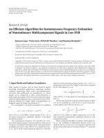
internal processing is illustrated in Figure 2.
Table 1: Summary of the sign LMS algorithm realized in BFP for-
mat (initial conditions: ψ
0
= 0, |w
k
(0)| < 1/2, k ∈ Z
L
, μ
0
= μ).
(1) Preprocessing:
using the data for the ith block, x(n)andd(n), n
∈ Z
i
, i ∈ Z
+
(stored during the processing of the (i − 1)th block).
(a) Evaluate block exponent γ
i
as per the exponent assignment
algorithm of Section 3 and express x(n), d(n), n
∈ Z
i
as
x(n)
= x(n)2
γ
i
, d(n) = d(n)2
γ
i
.
(b) Rescale the following elements of the (i
− 1)th block:
{x(n) | n = iN − L +1, , iN − 1} as
x(n) → x(n)2
−Δγ
i
, Δγ
i
= γ
i
− γ
i−1
(also, for Step 2
of Section 3, rescale the same separately by 2
−Δγ
i
+S
min
).
(2) Processing for the ith block:
For n
∈ Z
i
={iN, iN +1, , iN + N − 1}.
(a)Filteroutput:
y(n) = w
t
(n)x(n),
ex
out(n) = γ
i
+ ψ
n
(ex out(n) is the filter output exponent at the nth index).
(b) Output error (mantissa) computation:
e(n) = d(n)2
−ψ
n
− y(n).
(c) Filter weight updating:
compute
u
k
(n) = μ
n
x(n − k)2
γ
i
for all k ∈ Z
L
following Steps 1–3 of Section 3.
v(n) = w(n)+u(n)sgn{e(n)}
(where u(n) = [u
0
(n), u
1
(n), , u
L−1
(n)]
t
).
If
|v
k
(n)| < 1/2forallk ∈ Z
L
={0, 1, , L − 1}
then
w(n +1)= v(n),
ψ
n+1
= ψ
n
,
else
w(n +1)=
1
2
v(n),
ψ
n+1
= ψ
n
+1.
end.
μ
n+1
= μ
n
2
(ψ
n
−ψ
n+1
)
end
i
= i +1.
Repeat Steps 1 to 2.
4. COMPLEXITY ISSUES
The proposed scheme relies mostly on FxP arithmetic, re-
sulting in computational complexities much less than that
of their FP-based counterparts. For example, to compute the
filter output in Table 1 , L “multiply and accumulate (MAC)”
operations (FxP) are needed to evaluate
y(n) and at the most,
one exponent addition operation to compute the exponent
ex
out(n). In FP, this would require L FP-based MAC op-
erations. Note that given three numbers in FP (normalized)
format A
= A2
e
a
, B = B2
e
b
, C = C2
e
c
, the MAC oper-
ation A + BC requires the following steps: (i) e
b
+ e
c
, that
is, exponent addition (EA), (ii) exponent comparison (EC)
between e
a
and e
b
+e
c
, (iii) shifting either A or B/C, (iv) FxP-
based MAC, and finally, (v) renormalization, requiring shift
Mrityunjoy Chakraborty et al. 5
··· ···
Bufferring
(ith block)
Bufferring
((i + 1)th block)
···
···
···
···
···
···
···
···
BF
((i
− 1)th block)
BF
(ith block)
BF
((i + 1)th block)
···
···
···
···
Filtering
((i
− 2)th block)
Filtering
((i − 1)th block)
Filtering
(ith block)
Time
Figure 1: The relative timing of the three units (BF: block formatting).
and exponent addition. In other words, in FP, computation
of y(n) will require the following additional operations over
the BFP-based realization: (a) 2L shifts (assuming availability
of single cycle barrel shifters), (b) L EC, and (c) 2L
− 1EA.
Similar advantages exist in weight updating also. Tab le 2 pro-
vides a comparative account of the two approaches in terms
of number of operations required per iteration. Note that
the number of additional operations required under FP in-
creases linearly with the filter length L.Itiseasytoverifyfrom
Tabl e 2 that given a low cost, simple FxP processor with sin-
gle cycle MAC and barrel shifter units, the proposed scheme
is about three times faster than an FP-based implementation,
for moderately large values of L.
5. SIMULATION AND FINITE PRECISION
IMPLEMENTATION
The proposed scheme was implemented in finite precision
in the context of a system identification problem. A system
modelled by a 3-tap FIR filter was used to generate an output
y(n)
= 0.7x(n)+0.65x(n − 1) + 0.25x(n − 2) + v(n), with
v(n)andx(n) being the observation noise and the system in-
put, respectively, with the following variances: σ
2
v
= 0.008,
σ
2
x
= 1. The variance σ
2
y
of y(n)(≡ d(n)) was found to be
0.935. To calculate the upper bound of μ(
= 2
− ex
max
/2), the
quantity M
={|x(n)|, |y(n)||n ∈ Z} was calculated, as
1.99 max
{σ
x
, σ
y
}, so as to contain about 95% of the samples
of x(n)andy(n). This gives rise to ex
max
= 1 and thus the
upper bound of μ to be 0.25. Taking μ
= 2
−6
, block length
N
= 20, and allocating 12 bits (1 + 11) for the mantissas
and 4(1 + 3) bits for the exponents of both the data and the
filter coefficients, the proposed scheme was implemented in
VHDL. For this, the Xilinx ISE 7.1i software was used for a
target device of Xilinx Virtex series FPGA XCV1000bg (speed
grade 6). Details of this implementation like hardware re-
quirement, respective g ate counts, and execution times are
provided later in this section. Here we study the finite pre-
cision effects by plotting the learning curves for this as well
as for an FP-based realization under same precision for both
the exponent and the mantissa. The learning curves, shown
in Figure 3 by solid and dashed lines, respectively, demon-
strate that both these implementations have similar rates of
Block
formatting
algorithm
Compute filter weight
mantissa and exponent
(Eq. (8) and (9)),
using steps 1–3.
Update step-size mantissa
(Eq. (7))
Sign
x(n)
d(n)
d(n)
x(n)
Z
−1
Z
−1
2
−Δγ
i
2
−Δγ
i
w
2
(n)w
1
(n)w
0
(n)
y(n)
−
+
e(n)
2
−ψ
n
Figure 2: The proposed sign-LMS-based adaptive filter in BFP for-
mat. The shifting of
x(n − k), k = 1, 2 by 2
−Δγ
i
is done only at the
starting index of each block, that is, at n
= iN, i ∈ Z
+
.
Table 2: A comparison between the BFP vis-
`
a-vis the FP-based real-
izations of the sign LMS algorithm. Number of operations required
per iteration for (a) weight updating and (b) filtering is given.
(a) MAC Shift
Magnitude
check
Exponent
comparison
Exponent
addition
BFP LL+3 L Nil 1
FP L 2L Nil L 2L
(b) MAC Shift
Exponent
comparison
Exponent
addition
BFP L Nil Nil 1
FP L 2LL 2L
convergence. However, in the steady state, the BFP scheme
has slightly more excess mean square error (EMSE) than the
FP scheme, which may be caused by the block formatting of
data. This slight increase in EMSE is, however, offset by the
speedup that is achieved and verified by comparing the exe-
cution times of the proposed realization with its FP counter-
part.
6 EURASIP Journal on Advances in Signal Processing
0
0.2
0.4
0.6
0.8
1
1.2
1.4
1.6
1.8
2
E[|e(n)|
2
]
50 100 150 200 250 300 350 400
Number of iterations n
Figure 3: Learning curves for the finite precision implementation
of (a) the proposed BFP-based scheme (solid line), and (b) an FP-
based implementation (dashed line) with identical precision.
FPGA synthesis summary
The proposed scheme as well as the FP-based algorithm are
implemented using basic hardware units like adder, multi-
plier, register, multiplexer, shifter, and so forth. The step size
μ is taken to be a power of two as it eliminates the need
of multiplier in the weight update loop. For the proposed
scheme, the three stages, (a) buffering, (b) block format-
ting, and (c) filtering and weight updating have the following
hardware requirements.
(a) Buffering: this stage uses N 16 bit registers, where N is
the block length (N
= 20 for the example considered).
(b) Block formatting: this stage first computes e
max
=
max{(e
l
− n
L
) | l = 0, 1, , N − 1} (see Algorithm 1)by
employing a 4 bit subtractor, a 4 bit comparator, and a 4 bit
register for each l, l
= 0, 1, , N − 1. One 4 bit adder is used
next to compute the block exponent e
max
+ S
i
. Then, for each
l, l
= 0, 1, , N − 1, e
max
+ S
i
− e
l
is computed by using one
4 bit subtractor and the lth data mantissa is shifted left/right
by e
max
+S
i
− e
l
using two 12 bit shifters. The block formatted
mantissas are finally stored in N 12 bit registers.
(c) Filtering and weight updating: for filtering, a MAC op-
eration (FxP) is used iteratively L times where L is the fil-
ter o rder (L
= 3 for the example considered). The MAC
unit requires one 12
× 12 multiplier, one 24 bit adder, and
two 24 bit registers, one for holding the result of multipli-
cation and the other for storing the MAC output. This is fol-
lowed by computation of output error mantissa that uses one
12 bit shifter and one 12 bit subtractor. For updating each
tap weight, first note that since μ is a power of 2, that is,
μ
= μ
0
= 2
s
(say), we have μ
n
= 2
s
n
where s
n
= s − ψ
n
.For
updating
μ
n
, it is then enough to update s
n
,whichrequires
a 4 bit subtractor and a 4 bit register, but does not require
the shifter implied in the general update relation (7). The
Steps 1–3 of Section 3 also get simplified, as it is then suf-
ficient to use two 4 bit adders and one 4 bit register to com-
pute s
n
+ex
i
+S
min
,2L 12 bit shifters to shift x(n − k), k ∈ Z
L
left/right by s
n
+ex
i
+S
min
and L 12 bit adders/subtractors to
evaluate
v(n)asper(6). Finally, to realize the update rela-
tions (8)and(9), we need a 4 bit adder and a 4 bit register to
update ψ
n
,andL 12bitshiftersaswellasL 12 bit registers to
compute
w(n).
An FP-based realization, on the other hand, has only two
operations, namely, filtering and weight updating, both re-
quiring FP addition and multiplication. If two FP numbers
having r bit mantissa and m bit exponent each are multiplied,
we need one r
× r multiplier, one m bit adder, and two reg-
isters of length m bits and 2r bits. If, on the other hand, the
two numbers are added, we need one m bit comparator, one
m bit subtr actor, two r bit shifters, two r bit 2 : 1 MUX, one
r bit adder and for renormalization of the result, two r bit
shifters and one m bit adder/subtractor. We also need regis-
ters of length m bits and r bits for storing the mantissa and
exponent of the result of addition. To realize the filtering
operation, an FP-based MAC operation is used iteratively L
times that uses one FP multiplication with r
= 12 and m = 4,
and an FP addition with r
= 24 and m = 4. For computing
the output error, an FP addition with r
= 12 and m = 4is
deployed. For updating each weight, a 4 bit adder is used to
add the exponents of the step size and data, followed by an
FP addition with r
= 12 and m = 4.
The total equivalent gate count for the proposed scheme
with N
= 20 was found to be 9227, while the same for an
FP-based implementation was 12,468. The minimum clock
period needed for the FP-based implementation has b een
16.052 ns. For the proposed scheme, minimum clock peri-
ods required for the three stages, (a) buffering, (b) block
formatting, and (c) filtering and weight updating have been
0.232 ns, 4.575 ns, and 6.695 ns. In other words, the mini-
mum clock period needed for the proposed scheme has been
6.695 ns and thus the BFP realization is about 2.39 times
faster than the FP-based realization, which also conforms to
our observation from Ta ble 2 for L
= 3.
6. CONCLUSION
The sign LMS algorithm is presented in a BFP framework
that ensures simple FxP-based operations in most of the
computations while maintaining an FP-like wide dynamic
range via a block exponent. The proposed scheme is partic-
ularly useful for custom implementations on ASIC or FPGA,
where hardware and power efficiency constitute an impor-
tant factor. For identical resource constraints, the proposed
scheme achieves a speed-up in the range of 2 : 1 to 3 : 1 over
an FP-based implementation, as observed both from oper-
ational counts and also from a custom implementation on
FPGA. Finite precision-based simulations also did not show
up any noticeable difference in the convergence characteris-
tics, as one moves from the FP to the BFP format.
ACKNOWLEDGMENT
This work was supported in part by the Institute of Informa-
tion Technology Assessment (IITA), South Korea.
Mrityunjoy Chakraborty et al. 7
REFERENCES
[1] K. R. Ralev and P. H. Bauer, “Realization of block floating-
point digital filters and application to block implementations,”
IEEE Transactions on Signal Processing, vol. 47, no. 4, pp. 1076–
1086, 1999.
[2] S. Sridharan, “Implementation of state-space digital filter
structures using block floating-point arithmetic,” in Proceed-
ings of IEEE International Conference on Acoustics, Speech and
Signal Processing (ICASSP ’87), pp. 908–911, Dallas, Tex, USA,
April 1987.
[3] K. Kallioj
¨
arvi and J. Astola, “Roundoff errors in block-float-
ing-point systems,” IEEE Transactions on Signal Processing,
vol. 44, no. 4, pp. 783–790, 1996.
[4] S. Sridharan and G. Dickman, “Block floating-point imple-
mentation of digital filters using the DSP56000,” Microproces-
sors and Microsystems, vol. 12, no. 6, pp. 299–308, 1988.
[5] S. Sridharan and D. Williamson, “Implementation of high-
order direct-form digital filter structures,” IEEE Transactions
on Circuits and Systems, vol. 33, no. 8, pp. 818–822, 1986.
[6] F. J. Taylor, “Block floating-point distributed filters,” IEEE
Transactions on Circuits and Systems, vol. 31, no. 3, pp. 300–
304, 1984.
[7] A. Mitra, M. Chakraborty, and H. Sakai, “A block floating-
point treatment to the LMS algorithm: efficient realization and
a roundoff error analysis,” IEEE Transactions on Signal Process-
ing, vol. 53, no. 12, pp. 4536–4544, 2005.
[8] A. Mitra and M. Chakraborty, “The NLMS algorithm in block
floating-point format,” IEEE Signal Processing Letters, vol. 11,
no. 3, pp. 301–304, 2004.
[9] A. C. Erickson and B. S. Fagin, “Calculating the FHT in hard-
ware,” IEEE Transactions on Signal Processing,vol.40,no.6,pp.
1341–1353, 1992.
[10] D. Elam and C. Lovescu, “A block floating point implemen-
tation for an N-point FFT on the TMS320C55X DSP,” Appli-
cation Report SPRA948, Texas Instruments, Dallas, Tex, USA,
September 2003.
[11] E. Bidet, D. Castelain, C. Joanblanq, and P. Senn, “A fast single-
chip implementation of 8192 complex point FFT,” IEEE Jour-
nal of Solid-State Circuits, vol. 30, no. 3, pp. 300–305, 1995.
[12] M. Chakraborty and A. Mitra, “A block floating-point realiza-
tion of the gradient adaptive lattice filter,” IEEE Signal Process-
ing Letters, vol. 12, no. 4, pp. 265–268, 2005.
[13] B. Farhang-Boroujeny, Adaptive Filters—Theory and Applica-
tion, John Wiley & Sons, Chichester, UK, 1998.
Mrit yunjoy Chakraborty obtained Bache-
lor of engineering from Jadavpur univer-
sity, Calcutta, in electronics and telecom-
munication engineering (1983), followed
by Master of Technology and Ph.D. de-
grees both in electrical engineering from
IIT, Kanpur (1985) and IIT, Delhi (1994),
respectively. He joined IIT, Kharagpur, as a
faculty member in 1994, where he currently
holds the position of a Professor in electron-
ics and electrical communication engineering. The teaching and
research interests of him are in digital and adaptive signal process-
ing, including algorithm, architecture and implementation, VLSI
signal processing, and DSP applications in wireless communica-
tions. In these areas, he has supervised several graduate theses, car-
ried out independent research, and has several well-cited publica-
tions. He has been an Associate Editor of the IEEE Transactions
on Circuits and Systems I during 2004–2005 and also during 2006–
2007, he is a Guest Editor for an upcoming special issue of the
EURASIP JASP on distributed space time systems, has been in the
technical committee of many top-ranking international confer-
ences, and has visited many well-known universities overseas on
invitation. He is a fellow of the IETE and a Senior Member of IEEE.
Rafiahamed Shaik was bor n in Mogallur,
India, in 1970. He received the B.Tech.
and M.Tech. degrees from Sri Venkateswara
University, Tirupati, India, in 1991 and
1993, respectively. He is currently working
towards the Ph.D. degree at the Indian Insti-
tute of Technology, Kharagpur, India, all in
electronics and communication engineer-
ing. From 1993 to 1995, he has been a fac-
ulty member at Deccan College of Engi-
neering and Technology, Hyderabad, India, and from 1995 to 2003
at Bapatla Engineering College, Bapatla, India. His teaching and re-
search interests are in digital and adaptive signal processing, signal
processing for communication, microprocessor-based system de-
sign, and VLSI signal processing.
Moon Ho Lee received the Ph.D. degrees
in electronic engineering from the Chon-
nam National University, Korea (1984) and
the University of Tokyo, Japan (1990). From
1970 to 1980, he was a Chief Engineer with
Namyang Moonhwa Broadcasting Corp.,
Korea. Since 1980, he has been a Professor
with the Department of Information and
Communication at Chonbuk National Uni-
versity. From 1985 to 1986, he was also with
the University of Minnesota, as a Postdoctoral Research Fellow. He
has held visiting positions with the University of Hannover (1990),
the University of Aachen (1992, 1996), the University of Munich
(1998), the University of Kaiserlautern (2001), RMIT (2004), and
the University of Wollongong, Australia. He has authored 31 books
including Digital Communication (Youngil, Korea, 1999), and 1995
SCI international journal papers. His research interests include
multidimensional source and channel coding, mobile communi-
cation, and heterogeneous network. He is a registered Telecom-
munication Professional Engineer and a Member of the National
Academy of Engineering in Korea. He was the recipient of the Pa-
per Prize Award from the Korean Institute of Communication Sci-
ence in 1986 and 1997, the Korea Institute of Electronics Engineers
in 1987, Chonbuk Province in 1992, and Commendation of Prime
Minister, for basic research on jacket matrix theory and applica-
tions (2002).