Báo cáo hóa học: " Research Article Computationally Efficient Partial Crosstalk Cancellation in Fast Time-Varying DSL " pdf
Bạn đang xem bản rút gọn của tài liệu. Xem và tải ngay bản đầy đủ của tài liệu tại đây (1.4 MB, 15 trang )
Hindawi Publishing Corporation
EURASIP Journal on Advances in Signal Processing
Volume 2007, Article ID 72041, 15 pages
doi:10.1155/2007/72041
Research Article
Computationally Efficient Partial Crosstalk Cancellation in
Fast Time-Varying DSL Crosstalk Environments
Amir R. Forouzan and Lee M. Garth
Depar tment of Electrical and Computer Engineering, University of Canterbury, Private Bag 4800,
Christchurch 8020, New Zealand
Received 3 April 2006; Revised 5 December 2006; Accepted 17 December 2006
Recommended by Markus Rupp
Line selection (LS), tone selection (TS), and joint tone-line selection (JTLS) partial crosstalk cancellers have been proposed to re-
duce the online computational complexity of far-end crosstalk (FEXT) cancellers in digital subscriber lines (DSL). However, when
the crosstalk profile changes rapidly over time, there is an additional requirement that the partial crosstalk cancellers, particularly
the LS and JTLS schemes, should also provide a low preprocessing complexity. This is in contrast to the case for perfect crosstalk
cancellers. In this paper, we propose two novel channel matrix inversion methods, the approximate inverse (AI) and reduced in-
verse (RI) schemes, which reduce the recurrent complexity of the LS and JTLS schemes. Moreover, we propose two new classes of
JTLS algorithms, the subsort and Lagrange JTLS algorithms, with significantly lower computational complexity than the recently
proposed optimal g reedy JTLS scheme. The computational complexity analysis of our algorithms shows that they provide much
lower recurrent complexities than the greedy JTLS algorithm, allowing them to work efficiently in very fast time-varying crosstalk
environments. Moreover, the analytical and simulation results demonstrate that our techniques are close to the optimal solution
from the crosstalk cancellation point of view. The results also reveal that partial crosstalk cancellation is more beneficial in up-
stream DSL, particularly for short loops.
Copyright © 2007 A. R. Forouzan and L. M. Garth. This is an open access article distributed under the Creative Commons
Attribution License, which permits unrestricted use, distribution, and reproduction in any medium, provided the original work is
properly cited.
1. INTRODUCTION
The main impairments in digital subscriber lines (DSL) are
loop loss, crosstalk, background noise, impulse noise, and
radio ingress. For the short loop lengths of very high-speed
digital subscriber lines (VDSL), the dominant impairment is
far-end crosstalk (FEXT). Recently, FEXT cancellation tech-
niques in loops with coordination among the transceivers on
one side have been proposed. Coordination results in effec-
tive FEXT cancellation with higher performance and com-
plexity reduction [1]. However, the method and success of
FEXT cancellation techniques strongly depend on the degree
of coordination among the DSL transceivers and the avail-
able processing power. FEXT cancellation in downstream
(DS) and upst ream (US) discrete multitone (DMT) DSL can
be done by coordinating the transmitter and the receiver
modems, respectively.
In [2], a vector Tomlinson-Harashima precoder and in
[3] a simpler technique called the diagonalizing precom-
pensator have been proposed for crosstalk mitigation in DS
DSL. For US transmission, a zero-forcing-generalized deci-
sion feedback equalizer (DFE) has been proposed for FEXT
cancellation in [2]. In [4], it has been shown that the feed-
back portion of the DFE is not required, and a zero-forcing
linear equalizer is near optimum for US VDSL.
These methods achieve the channel capacity for each tone
very closely. However, new techniques requiring fewer com-
putations are of crucial importance because of the huge com-
plexity order of the system. In [5, 6], reduced complexity
techniques for FEXT cancellation in DS and US have been
studied. The proposed techniques decrease the computa-
tional complexity by ignoring crosstalk from nondominant
crosstalkers (line select ion) or by dedicating the processing
power to the frequency b ands where it is more beneficial
(tone selection) or by combining line and tone selection tech-
niques (joint tone-line selection).
Note that although the twisted-pair channel does not
change quickly [7], the crosstalk profile can change very
rapidly in DSL systems. These profile time variations can
be due to a variety of causes. Most obviously, they can be
2 EURASIP Journal on Advances in Signal Processing
caused by quiescent modes in DSL transmitters. For example,
a protocol, which reduces the transmitted power or switches
the modem to an idle state when there is no information
to be sent, would not only s ave money for the transmitter,
but would also reduce the crosstalk power in the loop plant
and allow other rate-adaptive modems to increase their rates
[7]. Such a power-reduction scheme would have dramatic
effect on the crosstalk profile as a significant share of traf-
fic over DSL lines is due to Internet web browsing includ-
ing variable-rate multimedia traffic. This bursty traffic yields
a minimum transmission power for each DSL user which
varies over time.
Such quiescent modes have been proposed in VDSL stan-
dards. For example, in short-term stationary VDSL systems,
including burst transmission systems and systems that use
quiescent modes, the transmitter is silent or generates only
a pilot tone to reduce power consumption and crosstalk lev-
els during idle IP packets [8]. Clause 5.4 of [9] describes the
activation and power control procedure for a VDSL trans-
mission unit (VTU). To reduce the crosstalk levels and radio
frequency interference (RFI) of the VDSL system during a
normal transmission session, the VTU dynamically switches
between the steady-state transmission state and an idle state,
a dynamic power-saving state, or a power-saving sleeping
mode. The transition between these states is expected to take
place in less than a hundred milliseconds. In more recent
ADSL2 and ADSL2+ standards, however, the power control
is activated within a time frame of seconds to minutes.
DSL systems can also be subject to time-varying crosstalk
profiles from different coexisting DSL services with differ-
ent symbol durations [10]. For example, in Annex F of [8]
the time-varying and user data-dependent nature of T1 AMI
and DDS systems has been studied, producing the conclusion
that “the time duration of each PSD variant may vary from
less than 1 millisecond to many hours.” These variations can
be greater than 20 dB and are caused by user data content.
As we will see in this paper, handling time-varying
crosstalk is much easier for systems with crosstalk cancella-
tion using a joint modem or a shared DSL access multiplexor
(DSLAM). For in these cases, the DSLAM can easily control
the power and bitrate of users in a joint fashion, avoiding
the delay due to resynchronization of distributed modems.
1
In particular, we show how the DSLAM can avoid delay in
partial crosstalk cancellation for fast time-varying crosstalk
environments.
Considering the large number of independent DSL users
in the cable, the crosstalk profile and therefore the set of
dominant crosstalkers can change very rapidly over time for
short-term stationary DSL systems. But the structures of par-
tial crosstalk cancellers, particularly the line selection (LS)
and joint tone-line selection (JTLS) schemes, depend sub-
stantially on the crosstalk profile and the set of dominant
crosstalkers. Consequently, in contrast to perfect FEXT can-
cellation techniques, the initialization and recurrent com-
plexity associated with partial crosstalk cancellers should be
1
See [11] for an algorithm to jointly control the bitrates of the users.
reconsidered. In this paper, we propose two new channel ma-
trix inversion (CMI) schemes and two novel classes of JTLS
algorithms to reduce the recurrent preprocessing require-
ments of partial crosstalk cancellers for US and DS DSL.
Our first CMI method is based on a recently proposed
power-series expansion technique for the inverse of the DSL
channel transfer matrix [12]. Our second CMI method re-
duces the recurrent computational complexity by storing the
inverse of the perfect channel matrix for each tone. When
any change occurs in the crosstalk profile, the new structure
for the partial crosstalk cancellers can be obtained from the
stored information in a computationally efficient way. This
method is a modified version of the scheme proposed in
[5, 6], in which channel inversion is required every time the
crosstalk profile changes over time. Since CMI is an essential
part of the LS and JTLS schemes, our new CMI techniques
result in a lower recurrent complexity for both the LS and
JTLS schemes.
We also propose two new classes of algorithms for joint
tone-line selection (JTLS). Our algor ithms are much faster
than a greedy algorithm recently proposed in [5, 6]. Our first
JTLS scheme, the subsort JTLS algorithm, is a heuristic ap-
proach, which can nearly achieve the performance of the op-
timal JTLS algorithm. Our second JTLS scheme employs the
Lagrange multiplier optimization technique to allocate the
processing power efficiently. Our results show that the La-
grange JTLS algorithm is almost optimal for practical DSL
channels.
The paper is organized as follows. In the next section, we
describe the DSL channel. We review perfect crosstalk cancel-
lation schemes in Section 3. We describe our partial crosstalk
cancellation schemes in Sections 4 to 6. We evaluate the com-
putational complexity of the new algorithms in Section 7.Fi-
nally, simulation results are presented in Section 8, and the
conclusion is given in Section 9.
2. DSL CHANNEL AND FEXT MODEL
Consider L VDSL users and the synchronized transmission
of DMT symbols. In this case, the transmitted and received
signals for each tone k can be arr anged in the following ma-
trix form [2]:
y
k
= H
k
x
k
+ n
k
,1≤ k ≤ N,(1)
where N is the number of DMT tones, and y
k
, x
k
,andn
k
are
the L-dimensional vectors of received, transmitted, and noise
samples for tone k,respectively.Theth elements of y
k
, x
k
,
and n
k
are denoted y
()
k
, x
()
k
,andn
()
k
,respectively.Matrix
H
k
is an L ×L channel transfer function for tone k, where the
(i, j)th matrix component h
(i, j)
k
= [H
k
]
ij
contains the single-
tap complex channel from transmitter j to receiver i.
Throughout this work, we assume that crosstalk cancel-
lation is performed by a joint modem or DSLAM located
at the line termination side (central office or remote termi-
nal). We assume that the modem has perfect knowledge of
the crosstalk channel H
k
on all tones in the DS and US di-
rections and is aware of active and idle DSL users and their
A. R. Forouzan and L. M. Garth 3
transmitting power in each tone. We first concentrate on the
downstream direction and then generalize our techniques to
upstream DSL.
3. PERFECT CROSSTALK CANCELLATION IN DMT DSL
When the transmitter modems are colocated (e.g., the DS
modems are colocated at the CO), the transmitted signals
can be generated from users’ data signals in a joint fash-
ion, and it is possible to cancel crosstalk perfectly in a DMT
DSL channel using vector coding schemes. In [2], a multiuser
Tomlinson-Harashima precoder has been proposed, and it
has been shown that the receiver nearly achieves the capac-
ity of the twisted-pair channel as if there is no crosstalk.
2
In
[3] a diagonalizing precompensator (DP) has been proposed,
which nearly achieves the channel capacity on each line as
well. In this paper, we consider DP for simplicity.
The diagonalizing precompensator consists of multiply-
ing the vector x
k
for each tone k by the following precoding
matrix prior to transmission:
P
k,DP
= β
k
H
−1
k
Λ
diag
H
k
,(2)
where H
−1
k
is the inverse of channel mat rix and β
k
is a nor-
malizing factor, which ensures that the spectral mask is not
exceeded on any line. Diagonal matrix Λ
= diag{H
k
} con-
tains the diagonal elements of H
k
. Therefore, if we define
H
k
Δ
= Λ
−1
H
k
,weget
P
k,DP
= β
k
H
k
−1
. (3)
It has been shown in [3] that β
k
1 for DSL loops. Thus, the
DP is simply a ZF precompensator for the normalized chan-
nel matrix
H
k
. However, in contrast to a ZF precompensator
with its constrained transmission power, the DP can nearly
achieve the capacity of crosstalk-free loops [3].
4. COMPLEXITY REDUCTION BY PARTIAL
CROSSTALK CANCELLATION
The perfect crosstalk cancellation schemes proposed in [2–4]
require O(L
2
N) operations per DMT symbol period. Since
the number of twisted pairs in a binder group is up to 100
and N is 4096 in VDSL, the computational complexity of
perfect crosstalk cancellers is too high for current processors
[5, 6]. Therefore, we consider suboptimal partial crosstalk
cancellation techniques.
It is widely accepted that the crosstalk to each loop is usu-
ally predominantly from a few crosstalkers, called the domi-
nant crosstalkers [5, 6, 13, 14]. In the upstream direction, the
dominant crosstalkers to a victim line are usually its neigh-
bouring lines in the binder or shorter loops in the binder,
2
Note that the cyclic prefix in DMT modulation results in a loss in the
capacity of the twisted pair channel regardless of the capacity loss due to
crosstalk.
which overwhelm other lines due to the near-far effect [14].
In downstream DSL, wh ere there is no near-far effect, the
dominant crosstalkers are the ones closer to the victim line
in the binder, assuming an equal transmission power in all
loops. Moreover, crosstalk cancellation does not have the
same benefit for all frequencies. Generally, at very low fre-
quencies crosstalk has a negligible effect on performance, and
at very high frequencies performance is bounded by the loop
loss and the receiver noise rather than crosstalk.
Line selection (LS) schemes cancel crosstalk from dom-
inant crosstalkers at all frequencies. Tone selection (TS)
schemes, on the other hand, only cancel crosstalk for the
tones which are most beneficial. LS and TS schemes improve
the performance when the processing power is not enough to
cancel all of the crosstalkers in all of the tones. However, su-
perior p erformance can be achieved using joint tone-line se-
lection (JTLS) schemes. In JTLS schemes, both the frequency
tones and the lines are considered to determine how to ex-
pend the available processing power to get the highest possi-
ble bitrates.
The structures of LS and JTLS partial crosstalk cancellers
depend substantially on the set of dominant crosstalkers. In
the following sections, we propose new CMI schemes and
novel JTLS algorithms to reduce the recurrent computational
complexity of these techniques.
5. PARTIAL CROSSTALK CANCELLATION BY
LINE SELECTION
A possible solution to the numerical complexity problem is
to restrict the crosstalk cancellation to the crosstalk result-
ing from the dominant crosstalkers only (line selection). LS
has been considered for downstream VDSL in [6]. In this
method, the subset of users with the most crosstalk energy
impinging on a victim line is selected, and their crosstalk is
cancelled employing a CMI technique.
Here, the output of each CMI technique is an approxima-
tion of the inverse of the channel matrix for each tone with
zero elements corresponding to the nondominant crosstalk-
ers. The zero elements are essential to reduce the computa-
tional complexity. In [5, 6], a method is proposed to make a
sparse partial crosstalk precompensator matrix P
k
with off-
diagonal nonzero elements only in the positions correspond-
ing to the dominant crosstalkers. Assuming that the number
of dominant crosstalkers per tone is p, the number of opera-
tions that the LS scheme requires per tone is O(pLN). In fast
time-varying DSL channels, the computational complexity
associated with updating P
k
also has to be considered. Using
the method in [5, 6], computation of P
k
is an O(L(p +1)
3
)
operation, where p<Lis the number of dominant crosstalk-
ers for each line.
When the state of any of the modems in the cable changes
from the steady-state transmission state to an idle state, the
set of dominant crosstalkers for the other users can change.
As a result, these users are required to recompute their par-
tial crosstalk cancellers P
k
for 1 ≤ k ≤ N.ForN tones,
this requires O(NL(p +1)
3
) operations. On one hand, the
users should switch between the idle and nonidle states as
4 EURASIP Journal on Advances in Signal Processing
quickly as possible to reduce their crosstalk levels and RFI
radiation. On the other hand, the computational constraints
of the modems can prevent them from updating their partial
crosstalk cancellers, which annihilates the potential gains of
partial crosstalk cancellation. Therefore, it is of crucial im-
portance for partial crosstalk cancellers to have a low recur-
rent computational complexity. In this section, we propose
two low complexity CMI techniques for DSL.
In order to evaluate the performances of our CMI tech-
niques, we compare the bitrates of the DSL loops using our
methods with their bitrates when the dominant crosstalk en-
tries are removed from the channel. For each tone k,wede-
fine a dominant crosstalk-cancelled (DCC) channel by
H
DCC
k
(i, j)
Δ
=
⎧
⎪
⎪
⎨
⎪
⎪
⎩
0ifj is a dominant
crosstalker for user i,
h
(i, j)
k
otherwise.
(4)
We call a partial crosstalk canceller an ideal partial crosstalk
canceller if it enables the VDSL users to achieve the same bi-
trates as they would achieve if they were communicating over
the DCC channel.
5.1. Approximate inverse CMI
The elements of
H
k
corresponding to the nondominant
crosstalkers can be zeroed to get a matrix
H
0
k
Δ
= H
k
−
Λ
−1
H
DCC
k
+ I
L
,whereI
L
is the L × L identity matrix. Assum-
ing an equal transmission power for all of the modems,
H
0
k
is simply formed by zeroing the smaller elements in each row
of
H
k
. For the case w hen the transmission power of all of
the modems is not the same, the elements with minimum
s
( j)
k
|h
(i, j)
k
|
2
are nulled, where s
( j)
k
is the t ransmission power of
modem j on tone k.
Theapproximateinverse(AI)CMImethoduses(
H
0
k
)
−1
as an approximation to the ideal partial crosstalk canceller
and then uses a power-series approximation for matrix in-
version to efficiently compute (
H
0
k
)
−1
and to get a sparse pre-
coding matrix. Precise calculation of (
H
0
k
)
−1
requires O(L
3
)
operations for each tone. Moreover, (
H
0
k
)
−1
is not generally
a sparse matrix, which is essential in complexity reduction.
To overcome these problems, we use the first-order terms of
a power-series expansion. Use of a power-series expansion
for the inverse of the DS channel-transfer matrix has been
proposed in [12] to decrease the computational complexity
of perfect crosstalk cancellation. The results reported in [12]
predict a poor performance for the first-order power-series
expansion of the exact inverse of H
k
for short loops. Never-
theless, here we demonstrate that this method can be effec-
tively used for partial crosstalk cancellation.
Using the first-order terms of a power-series expansion
for the inverse of (
H
0
k
)
−1
,wehave
β
k
H
0
k
−1
β
k
2I
L
− H
0
k
Δ
= P
AI
k
,(5)
or
P
AI
k
ij
=
⎧
⎨
⎩
β
k
, i = j,
−β
k
H
0
k
ij
, i = j,
(6)
where
β
k
1 is a normalizing factor and I
L
is the L ×L iden-
tity matr ix. In Appendix A, we show that (
H
0
k
)
−1
reduces the
power of the dominant crosstalkers to a level much lower
than the crosstalk due to the nondominant crosstalkers. In
Appendix B, we show that the condition number of
H
0
k
is
bounded by
λ
max
H
0
k
λ
min
H
0
k
≤
1+pα
1 − pα
,(7)
where λ
max
H
0
k
and λ
min
H
0
k
are the biggest and smallest eigenval-
ues of
H
0
k
,respectivelyandα<0.01 (see Appendix A for
the definition of α). The right-hand side of (7) approaches
one as α
→ 0. Since the number of dominant crosstalkers
to each user p is typically around 3 to 4, we expect that the
power-series expansion has a fast convergence to (
H
0
k
)
−1
.As
we show later in our simulation results, in contrast to per-
fect crosstalk cancellation, the performance of the AI scheme
is very close to that of the ideal solution when employed in
partial crosstalk cancellation.
5.2. Reduced inverse CMI
In the reduced inverse (RI) CMI scheme, we compute and
store the structure of the perfect crosstalk cancellers, that is,
(H
k
)
−1
for 1 ≤ k ≤ N, at network setup. Since the DSL
crosstalk channel is essentially stationary, this data does not
need to be recalculated for long periods of time.
3
The par-
tial crosstalk cancellers are then simply calculated each time
there is a change in the set of dominant crosstalkers by zero-
ing the elements of (
H
k
)
−1
corresponding to the nondomi-
nant crosstalkers. This is written as
P
RI
k
ij
Δ
= β
k
⎧
⎪
⎪
⎨
⎪
⎪
⎩
0ifj is a nondominant,
crosstalker for user i,
H
k
−1
ij
otherwise.
(8)
Our simulation results show that the RI scheme almost
achieves the performance of the ideal partial crosstalk can-
celler.
5.3. Generalization to upstream direction
As we discuss in Appendix A, the downstream DSL channel
exhibits row-wise diagonal dominancy. The upstream DSL
3
Although the DSL channel is essentially stationary, it may change over
time because of several reasons such as change in customer wiring or tem-
perature change. In pra ctice, the DSL MIMO channel estimates must be
updated and the matrix channel inverses must be recalculated if the chan-
nel has changed. In this paper, we ignore the computational complexity
due to DSL channel changes.
A. R. Forouzan and L. M. Garth 5
channel, on the other hand, exhibits columnwise diagonal
dominancy (CWDD) [2] (i.e., the diagonal elements of the
US channel matrix are much larger than the off-diagonal ele-
ments in the same column). Recall that for the DS direction,
we formed the normalized channel transfer mat rix by pre-
multiplying H
k
by Λ
−1
. For the US direction, we form the
normalized channel transfer matrix by post-multiplying H
k
by Λ
−1
, that is,
H
k
Δ
= H
k
Λ
−1
. (9)
Using the CWDD property of the DS DSL channel, it is sim-
ple to show that
α
Δ
= max
i
max
j=i
h
(i, j)
k
1, (10)
where h
(i, j)
k
Δ
= [H
k
]
ij
.
It has been shown in [4] that a ZF equalizer is near op-
timal for US DSL. The ZF equalizer for US DSL consists of
multiplying the received vector by the inverse of the channel
transfer matrix followed by a slicer. Based on (1), at the re-
ceiver we can estimate the transmitted signal vector x
k
using
x
k
= H
−1
k
y
k
= Λ
−1
ΛH
−1
k
y
k
= Λ
−1
H
−1
k
y
k
. (11)
Note that there is no need for a normalizing fac tor β
k
in
the US direction. The diagonal matrix Λ
−1
has only a scal-
ing effec t on the slicer’s thresholds. As H
k
has exactly the
same properties as
H
k
in (3), it is trivial to show that all
of the results we have obtained in Section 5 for the down-
stream channel can be generalized to the upstream channel.
More importantly, the computationally efficient channel ma-
trix inversion schemes proposed in Sections 5.1 and 5.2 can
be implemented in an analogous way. As we show by using
simulations in Section 8, the proposed CMI schemes also es-
sentially achieve the performance of the ideal partial crosstalk
canceller in the US direction.
It is important to note that if a prewhitening filter W
k
is
used, we must replace H
k
by the equivalent noise-whitened
channel W
k
H
k
in the corresponding formulas. Unfortu-
nately, the CWDD property may not necessarily hold for this
channel. In this paper, we assume that the elements of the
received noise vector n
k
are independent, and we ignore the
prewhitening filter W
k
. The CMI techniques that we have in-
troduced in this paper can still be applied to channels with
correlated noise. However, their performance might be de-
graded with respect to the simulation results in this paper.
6. JOINT TONE-LINE SELECTION
In JTLS schemes, both the frequency tones and the lines are
considered to determine how to expend the available pro-
cessing power to get the highest possible bitrates. In these
schemes, the number of dominant crosstalkers that are can-
celled varies from tone to tone and line to line. We let ρ
()
k
denote the number of crosstalkers that are cancelled on tone
k of line . A JTLS algorithm first determines the value of ρ
()
k
for all users and tones. It then forms sparse partial crosstalk
cancellation matrices using a CMI scheme such as the AI and
RI schemes proposed in Section 5.
Given pN multiplications per user (if an average of p
dominant crosstalkers are cancelled per tone),
4
the JTLS
problem for user is written as [6]
max
{ρ
()
k
}
k=1, ,N
k
c
()
k
s.t.
k
ρ
()
k
≤ pN, (12)
where c
()
k
is the number of bits that can be loaded on the
kth tone of user after c ancelling ρ
()
k
dominant crosstalkers
on this tone. We assume that the power of the users and the
channel values are constant each time the algorithm is run.
Assuming ρ
()
k
dominant crosstalkers are cancelled, c
()
k
is
calculated as
c
()
k
= log
2
⎛
⎜
⎝
1+
1
Γ
s
()
k
h
(,)
k
2
σ
2
(k,)
+
L
j
=1, j=, j/∈D
k
(ρ
()
k
)
s
( j)
k
h
(,j)
k
2
⎞
⎟
⎠
,
(13)
where s
()
k
= E{|x
()
k
|
2
}, σ
2
(k,)
= E{|n
()
k
|
2
}, Γ is the signal-to-
noise power ratio (SNR) gap [15], and D
k
(ρ
()
k
) is the set of
the ρ
()
k
largest dominant crosstalkers for user in tone k.It
is clear that the larger ρ
()
k
is, the larger c
()
k
is. Therefore, in
practice the optimal solution satisfies the equality condition
k
ρ
()
k
= pN. Note too that the alien noise power is con-
tained in σ
2
(k,)
. Therefore, the optimal JTLS partial crosstalk
canceller should be recalculated from time to time in the
presence of alien time-varying crosstalk, even if the DSL sys-
tem does not have power control mode itself.
A greedy joint tone-line selection algorithm has been
proposed in [5, 6]. In this step-by-step algor ithm, the benefit
of cancelling any number of crosstalkers is calculated for all
of the tones, and in each step the crosstalkers with the most
benefit from cancellation are added to the cancellation list.
After adding them, the benefit of crosstalk cancellation for
the remaining crosstalkers is updated, and the process is re-
peated until all of the processing power is consumed. The
benefit of cancelling ρ crosstalkers on tone k of line is cal-
culated using v
()
k
(ρ) = (c
()
k
(ρ) − c
()
k
(0))/ρ. At the initializa-
tion, the benefit is calculated for all values of ρ
= 1, , L − 1
and all of the tones k
= 1, , N for line . During each
iteration, first the maximum b enefit value for line is se-
lected. If we denote the tone and number of crosstalkers of
the largest benefit value to be k
s
and ρ
s
, then the number
of crosstalkers to be cancelled in tone k
s
is set to ρ
s
.Andfi-
nally, the update process is performed by zeroing v
()
k
s
(ρ)for
1
≤ ρ ≤ ρ
s
and setting v
()
k
s
(ρ) = (c
()
k
s
(ρ) − c
()
k
s
(ρ
s
))/(ρ − ρ
s
)
for ρ
s
+1≤ ρ ≤ L − 1.
4
In practice, some of the N tones can be neglected, depending on the t rans-
mission direction and the bandplan. Accordingly, N should be replaced
by the actual number of tones that are used in the transmission for that
particular direction.
6 EURASIP Journal on Advances in Signal Processing
By inspec tion, we realize that the algorithm is optimal,
as it expends each bit of processing power for the most
possible benefit in each step. The algorithm requires up to
NL sort operations, which can have sizes as large as NL
[6]. Therefore, using a fast-sort algorithm with computa-
tional complexity O(NLlog
2
(NL)), the computational com-
plexities of the algorithm for one user and for the total L
users are O(N
2
L
2
log
2
(NL)) and O(N
2
L
3
log
2
(NL)), respec-
tively. Given the large number of tones in VDSL and twisted
pairs in a t ypical cable, it is clear that much faster algo-
rithms are required for fast time-varying crosstalk environ-
ments. A suboptimal JTLS algorithm for upstream DSL is
proposed in [5] with a computational complexity for one
user of O(NLlog
2
(NL)). We now propose two types of novel
JTLS algorithms for both downstream and upstream DSL
with much lower computational complexities than the op-
timal algorithm proposed in [5, 6].
6.1. Subsort JTLS algorithms
The family of subsort JTLS algorithms contains heuristic a l-
gorithms derived from the greedy JTLS algorithm in [5, 6].
Consider the benefit value selected at each step. It is easy to
show that the benefit value is less than the benefit value se-
lected at the previous step. As a result, on average we expect
the aggregate benefit of the selected tone in each step (i.e.,
v
()
k
s
(ρ
s
) = (c
()
k
s
(ρ
s
) − c
()
k
s
(0))/ρ
s
) to be less than the aggregate
benefit value of the tone selected at the previous step. The
class of subsort algor ithms that we propose here is based on
this observation.
In these algorithms, we first calculate the benefit values
v
()
k
(ρ) for all values of k and ρ at the initialization. If we de-
note
v
()
k
s
(ρ
s
)
= θ
∗
at the final step of the greedy algorithm,
to find θ
∗
, we consider an arbitrary threshold value θ (e.g.,
θ
= 0.5) and then perform one of the following algorithms.
Algorithm 1. For each t one k find the smallest ρ
()
k
with ben-
efit v
()
k
(ρ
()
k
) ≥ θ.Setρ
()
k
= L − 1, if no ρ
()
k
is found with
v
()
k
(ρ
()
k
) ≥ θ. Search for the largest threshold value θ that
satisfies
N
k
=1
ρ
()
k
≤ pN.
Algorithm 2. For each tone k find the largest ρ
()
k
with ben-
efit v
()
k
(ρ
()
k
) ≤ θ.Setρ
()
k
= 0, if no ρ
()
k
is found with
v
()
k
(ρ
()
k
) ≤ θ. Search for the largest threshold value θ that
satisfies
N
k
=1
ρ
()
k
≤ pN.
Algorithm 3. For each t one k find the smallest ρ
()
k
with ben-
efit v
()
k
(ρ
()
k
) ≤ θ.Setρ
()
k
= L − 1, if no ρ
()
k
is found with
v
()
k
(ρ
()
k
) ≤ θ. Search for the smallest threshold value θ that
satisfies
N
k
=1
ρ
()
k
≤ pN.
Algorithm 4. For each tone k find the largest ρ
()
k
with ben-
efit v
()
k
(ρ
()
k
) ≥ θ.Setρ
()
k
= 0, if no ρ
()
k
is found with
v
()
k
(ρ
()
k
) ≥ θ. Search for the smallest threshold value θ that
satisfies
N
k=1
ρ
()
k
≤ pN.
For the above algorithms to work, we need to show that
we can find an appropriate value of threshold θ that satisfies
the processing power constraint
ρ
()
k
≈ pN.Infact,forany
of these algorithms we will show that the processing power
ρ
()
k
is an increasing or decreasing function of θ.
Theorem 1. The processing power
ρ
()
k
is an increasing func-
tion of threshold value θ in Algorithms 1 and 2 and a decreasing
function in Algorithms 3 and 4.
Proof. Here we prove Theorem 1 for the first algorithm and
leave the others to the reader. Assume that θ
1
≥ θ
2
for an ar-
bitrary tone k. We denote the values of ρ
()
k
corresponding to
θ
1
and θ
2
by ρ
()
k
(θ
1
)andρ
()
k
(θ
2
), respectively. For ρ
()
k
(θ
1
) =
L − 1, clearly ρ
()
k
(θ
1
) ≥ ρ
()
k
(θ
2
). For ρ
()
k
(θ
1
) <L− 1, we
have v
()
k
(ρ
()
k
(θ
1
)) ≥ θ
1
,andthusv
()
k
(ρ
()
k
(θ
1
)) ≥ θ
2
. Since
ρ
()
k
(θ
2
) is the smallest number that satisfies v
()
k
(·) ≥ θ
2
,we
must have ρ
()
k
(θ
1
) ≥ ρ
()
k
(θ
2
). Summing over all values of k,
we get
ρ
()
k
(θ
1
) ≥
ρ
()
k
(θ
2
).
Theorem 1 guarantees that the processing power is a
monotonic function of θ. Therefore, we can search for the
proper value of θ that satisfies the processing power con-
straint by simply using classic search schemes such as a bi-
section search. However, note that this value is not necessar-
ily equal to θ
∗
, because, as we will see later, the subsort algo-
rithms do not yield the same results as the greedy algorithm.
6.2. Lagrangian JTLS algorithm
The Lagrangian JTLS algorithm is based on the Lagrange
multiplier method for constrained optimization, which is
written here as [16]
max
{ρ
()
k
}
k
L =
k
c
()
k
+ λ
pN −
k
ρ
()
k
, (14)
where λ
≥ 0 is the Lagrangian multiplier. The dimension of
the Lagrangian in (14) is extremely large. However, note that
c
()
k
is independent of c
()
k
and ρ
()
k
for k = k
. Therefore, fol-
lowing the methodology as in [17], we can decouple the La-
grangian in (14) into N independent Lagrangians per tone,
as follows:
max
ρ
()
k
L
k
= c
()
k
− λρ
()
k
, k = 1, , N. (15)
Note that L
= λpN +
k
L
k
.
For a particular value of λ, the optimal value of ρ
()
k
is ob-
tained by examining all integer values of ρ
()
k
from 0 to L − 1
in (15). The optimal value of λ, λ
∗
is the one that satisfies the
processing constraint
ρ
()
k
≈ pN.Tofindλ
∗
, we first start
with an arbitrary value of λ (e.g., λ
= 1) and compute ρ
()
k
for 1 ≤ k ≤ N from (15). Then, we increase or decrease λ,
A. R. Forouzan and L. M. Garth 7
conditioned on
ρ
()
k
being greater or less than pN,respec-
tively.Werepeatthisprocedureuntilλ converges. At con-
vergence, either the processing constraint is satisfied or λ
∗
is
zero .
The optimality of the algorithm could be shown if the
primal problem in (12)wasconvex[16]. Although this can-
not be shown for DSL channels, it has been shown that
when a time-sharing property is valid, the Lagrange mul-
tiplier method is optimal in multicarrier systems [18]. For
the time-sharing property to occur in multicarrier systems,
the number of subcarriers contributing to the signal at the
receiver side should be infinite.
5
This is practically the case
in high SNR loops, where hundreds to thousands of tones
contribute to the signal power. On the other hand, for low
SNR loops, where only a few tones contribute to the signal
power, the processing power is almost always enough for per-
fect crosstalk cancellation on all of these tones. It is easy to
show that the Lagrange JTLS algorithm converges to the op-
timal solution in this case. This justifies why the Lagrange
JTLS algorithm is always optimal in practice. As we will show,
our computer simulations verify this conclusion. This algo-
rithm has recently been independently proposed by Tsiaflakis
et al. [11].
7. COMPUTATIONAL COMPLEXITY
The total computational complexity of the partial crosstalk
cancellers is the sum of the online and recurrent computa-
tional complexities. The online computational complexity is
pN operations for e ach user per each DMT symbol for both
the LS and JTLS schemes, when an average of p crosstalk-
ersiscancelledforeachtone.TheDMTsymbolperiodis
250 μs in VDSL. In the following sections, we study the order
of the recurrent operations needed by the partial crosstalk
cancellers when the crosstalk profile varies over time. For a
binder with tens of VDSL loops carrying variable rate traf-
fic, it is expected that recomputation of the structure of the
partial crosstalk cancellers is required every few milliseconds.
Therefore, a practical par tial crosstalk canceller should re-
quireasfewrecurrentoperationsaspossible.
7.1. Computational complexity of LS schemes
The recurrent operations associated with the LS schemes in
fast time-varying crosstalk environments consist of the fol-
lowing two phases: (1) sorting the crosstalkers to determine
the dominant crosstalkers (tracking), (2) calculation of the
sparse partial crosstalk cancellation matrices based on the or-
der of the crosstalkers and the value of p (CMI).
Phase 1. Tracking requires N sorts of size L
−1foreachuser,
which is of order O(N(L
−1) log
2
(L −1)). If the users trans-
mit only at the maximum power mask level when working
and at zero power when idle, we can use a radix sort [19]to
5
For a detailed definition of the time-sharing property and the proof of the
optimality of the Lagrange optimization technique in multicarrier sys-
tems when the number of subcarriers is large see [18].
reduce the computational complexity to O(N(L−1)).
6
More-
over, if we assume that only one crosstalker has changed its
power, even for a random channel and unlimited power lev-
els, resorting the crosstalkers requires only O(N(L
− 1)) op-
erations.
Phase 2. CMI does not require any further data process-
ing when the dominant crosstalkers are determined using
our proposed AI and RI schemes. There are only NL as-
signment operations per user associated with (6)and(8).
In comparison, note that using the method proposed in
[5, 6] to construct the sparse partial crosstalk cancellers re-
quires O(N(p +1)
3
) calculations for each user and a total of
O(NL(p +1)
3
) operations for all users. Moreover, there are
N(L + p) assignment operations for this method as well.
7.2. Computational complexity of JTLS schemes
The recurrent operations associated with the JTLS schemes
in fast time-varying crosstalk environments consist of the fol-
lowing four phases: (1) tracking, (2) evaluating c
()
k
(·)and
v
()
k
(·)for1 ≤ k ≤ N, (3) determining ρ
()
k
by means of
a JTLS algorithm, (4) implementing CMI. We studied the
computational complexity of tracking and CMI in the pre-
vious section. The computational complexity of tracking in
JTLS is the same as in LS. It can be shown that the computa-
tional complexity of CMI in JTLS is greater than or equal to
LS, when the parameter p is the same for the two schemes.
We now study the computational complexity associated with
Phases 2 and 2 for the th user when a change occurs in
its crosstalk profile. The total computational complexity is
L times the computational complexity for a single user .
Phase 2. After sorting the crosstalkers, c
()
k
(ρ)canbecalcu-
lated using (13). Calculation of c
()
k
(ρ)(0≤ ρ ≤ L − 1) for
each tone k canbedoneinO(L) operations by evaluating
c
()
k
(ρ) for the maximum value of ρ (i.e., L − 1) down to 0.
This way, calculation of c
()
k
(ρ)in(13)foreachvalueofρ
canbedoneinO(1) operations, given that we have stored
the denominator of the fraction of the previous value of ρ.
Therefore, the calculation of c
()
k
(·)andv
()
k
(·) for all tones
1
≤ k ≤ N can be done in O(NL) operations for each user.
Phase 3. Determining ρ
()
k
is the core phase of the JTLS al-
gorithms. The computational complexity of this phase is
O(N
2
L
2
log
2
(NL)) for each user for the greedy algorithm
proposed in [5, 6]. For all of the subsort algorithms, the com-
putational complexity is O(K
1
NL)foreachuser,whereK
1
is
the number of iterations required to find the proper value
6
The radix sort is feasible when the numbers to be sorted are from a finite
set of preknown values. A Boolean array is formed with size equal to the
total number of possible values. The index of each element corresponds
to a particular value, and the indices are presorted. First, all of the ele-
ments are preset to false. In the sort process, the elements corresponding
to numbers in the list are set to tr ue. Finally, the sorted list can be achieved
by reading the values with corresponding boolean entries set to true.
8 EURASIP Journal on Advances in Signal Processing
of the threshold θ. Similarly, the computational complexity
of the proposed Lagrangian JTLS algorithm is O(K
2
NL)for
each user, where K
2
is the number of iterations required to
find the optimal Lagrange multiplier λ
∗
.
The required number of iterations depends on the de-
sired precision. Threshold value θ and Lagrangian multiplier
λ have values ranging from 0 to 15, with at most 15 bits
loaded on a given tone. Therefore, for the error to be smaller
than
x
, the number of required iterations is log
2
(15/
x
) −1.
For example, for
x
= 0.01 the number of required iterations
is 10. Similarly, the maximum processing power correspond-
ing to perfect crosstalk cancellation is N(L
−1). Therefore, for
the error in processing power to be smaller than
y
, we need
log
2
[N(L −1)/
y
] −1 iterations on average. If we assume an
average of p-dominant crosstalkers to be cancelled per tone
and 1% error in processing power, we get
y
= 0.01Np,and
the number of required iterations is log
2
[100(L − 1)/p] − 1.
When the available processing power is 20% of the required
processing power, the number of iterations is approximately
8. Our simulations results show that K
1
= 10 to 14 iterations
and K
2
= 6 to 11 iterations are usually enough to find the op-
timal values of θ and λ almost exactly. K
1
and K
2
can possibly
be reduced using faster search methods like the sub-gradient
search method as explained in [18]. In summary, we see that
the largest portion of the processing complexity (see Phase 3)
can be reduced significantly using the algorithms proposed in
this article.
7.3. Calculation of computational complexity
The order of the total required number of floating point op-
erations per second (flops) can be calculated using
O
total
= f
s
× O
online
+ f
update
× O
recurrent
, (16)
where f
s
= 4000 Hz is the DMT symbol rate and O
online
is the
order of online computational complexity. O
online
is equal to
LN and pN for perfect and partial crosstalk cancellers, re-
spectively. f
update
is the update rate (the rate of change in
the overall crosstalk profile) and O
recurrent
is the order of re-
current computational complexity. O
recurrent
is zero for per-
fect crosstalk cancellers. It can be calculated for LS and JTLS
schemes by summing the computational complexities corre-
sponding to the phases discussed in this section.
As an example of order calculation using (16), we let the
number of users be L
= 25 and the average number of dom-
inant crosstalkers to be cancelled per tone be p
= 5. Param-
eter N is set to 1174, the number of tones in the US direc-
tion of the VDSL FDD 998 bandplan [20]. With L
= 25
and p
= 5, the online computational complexity of the par-
tial crosstalk cancellers is pLN/L
2
N = p/L = 20% of the
perfect crosstalk canceller. However, the recurrent computa-
tional complexities of the partial crosstalk cancellers increase
with the update rate.
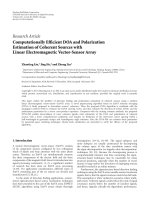
Figure 1 illustrates the order of the total number of flops
per user that are required for a perfect crosstalk canceller
(perfect CC), for the LS and JTLS partial crosstalk cancellers
proposed in this paper (new LS and new JTLS assuming
Table 1: Simulation parameters.
Tone width 4.3125 kHz
Symbol rate
4kHz
Γ
12.9 dB
Transmission power
−60 dBm/Hz
Cable type
26 Gauge (0.4 mm) [8]
Load resistance
135 Ω
Noise model
ETSI Noise Model A [20]
Target error Prob.
10
−7
Band plan 998 FDD Bandplan [20]
K
1
= K
2
= 11), and for the LS and JTLS partial crosstalk
cancellers proposed in [5, 6] (old LS and old JTLS). We have
provided closeups of Figure 1(a) in Figures 1(b) and 1(c) to
make the results more readable. We can see in Figures 1(a)
and 1(b) that the increase of the computation complexity as
a function of the update rate is very small using our new AI
and RI LS schemes (2.5% increase in the total computational
complexity for f
update
= 500 Hz). The old LS scheme, pro-
posed in [5, 6], also performs well compared to the old JTLS
scheme. It, however, increases the total computational com-
plexity by 24% for f
update
= 500 Hz.
AsitcanbeseeninFigures1(a) and 1(c), the total com-
putational complexity of the JTLS scheme in [5, 6]isvery
large in rapidly-varying crosstalk environments. For update
rates greater than about 0.2 Hz, the total computational com-
plexity of the scheme is even higher than the perfect crosstalk
canceller. Our new JTLS schemes, however, provide a sig-
nificantly lower computational complexity. We note that in
Figure 1(b), even for the very high update rate of 500 Hz (up-
date every 2 milliseconds), the increase in the computational
complexity due to the recurrent complexity is about 30%. In
comparison, to keep the increase in the computational com-
plexity below 30% in the old JTLS scheme, the update rate
should be less than 0.014 Hz (update every 71 seconds).
8. SIMULATION RESULTS
Having compared the relative computational complexities of
the schemes, we now use worst-case channel simulations to
compare the performances of the various techniques from a
crosstalk-cancellation point of view. We have simulated the
proposed algorithms for two typical scenarios for both the
DS and US directions. Scenario 1 is a distributed scenario,
and Scenario 2 is a near-far scenario. Scenario 1 consists of
10 VDSL users with lines varying in length from 300 m to
1200 m in 100 m increments. Scenario 2 consists of five VDSL
users with 600 m line lengths and five with 300 m line lengths.
The channel transfer matrix, H
k
, is simulated using the one
percent worst-case coupling model in [20] and the line trans-
fer function of [8]. The simulation parameters are listed in
Tabl e 1.
To see the benefits of a par tial crosstalk canceller, we
need to simulate a crosstalk channel which has a few dom-
inant crosstalkers. To do this, we model the space selectiv-
ity of crosstalk [6] by taking the distance-squared law of
A. R. Forouzan and L. M. Garth 9
0.01 0.1 1 10 100 500 4000
1e8
5.87e8
29.4e8
1e10
1e11
1e13
5e13
Update rate (Hz)
Tot al flo ps pe r s ec on d
Perfect CC
New LS
Old LS
New JTLS
Old JTLS
(a)
100 250 500 1000 4000
58.7e7
70.4e7
76.3e7
172e7
200e7
294e7
Update rate (Hz)
Tot al flo ps pe r s ec on d
Perfect CC
New LS
Old LS
New JTLS
(b)
0.01 0.10.18
58.7e7
100e7
294e7
Update rate (Hz)
Tot al flo ps pe r s ec on d
Perfect CC
New LS
Old LS
New JTLS
Old JTLS
(c)
Figure 1: (a) The total number of flops (including online and recurrent complexities) per user for perfect crosstalk canceller (perfect CC),
our new LS scheme (new LS), the LS scheme in [5, 6] (old LS), our new JTLS schemes (new JTLS) assuming K
1
= K
2
= 11, and the JTLS
scheme in [5, 6](oldJTLS)forL
= 25 and p = 5, (b) a closer look at the performance of our LS scheme, the LS scheme in [5, 6], and our
newJTLSschemeand(c)acloserlookattheperformanceoftheJTLSschemein[5, 6].
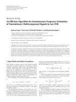
electromagnetic induction into account. Figure 2 illustrates
the cross-sections of the simulated 25-pair binder group for
the two scenarios. Each circle represents a twisted pair. The
length of each VDSL loop is written in the corresponding cir-
cle. The crosstalk couplings between pairs are considered to
be inversely proportional to the square of the distance be-
tween the centers of the corresponding circles in Figure 2.
7
As a worst-case scenario, we select a tightly packed subset of
7
The electromagnetic induction of twisted pairs into each other may not
exactly follow the distance-squared law. However, our simulation results
with a wide range of other powers for distance, ranging from
√
2to4,
show that this does not affect the results reported in this article.
pairs at the center of the binder. The crosstalk couplings are
normalized so that they are equal to the one percent worst-
case model for tangent circles (e.g., pairs 1 and 2, 1 and 3, 2
and 7, etc.). If we order the crosstalkers by power, Figure 3
shows the resultant cumulative average crosstalk power per-
centages for the 10 loops for the DS direction of Scenario
1, using the distance-squared law. This figure has a sim-
ilar shape to the experimental measurements reported in
Figure 3 of [6].
Figures 4 and 5 show the performances of the LS schemes
using the proposed CMI techniques for Scenarios 1 and 2, re-
spectively. As it can be seen, both schemes nearly achieve the
performance of the ideal LS partial crosstalk canceller. The
10 EURASIP Journal on Advances in Signal Processing
1
300 m
2
400 m
3
500 m
4
600 m
5
700 m
6
800 m
7
900 m
8
1000 m
9
1100 m
10
1200 m
11
12
13
14
15
16
17
18
1920
21
22
23
24
25
(a)
1
600 m
2
600 m
3
600 m
4
600 m
5
600 m
6
300 m
7
300 m
8
300 m
9
300 m
10
300 m
11
12
13
14
15
16
17
18
1920
21
22
23
24
25
(b)
Figure 2: Cross-section of the binder and corresponding VDSL loop lengths: (a) distributed Scenario 1, (b) near-far Scenario 2.
123456789
0
10
20
30
40
50
60
70
80
90
100
Crosstalkers stored in order of power
Percentage of total crosstalk
Figure 3: Cumulative average crosstalk percentages in DS direction
for distributed Scenario 1 (crosstalkers are sorted by power).
RI scheme has a slightly superior performance to that of the
AI scheme, especially for higher values of p.Thisisbecause
of three phenomena. Firstly, as p increases a bigger fraction
of the error is due to the residual crosstalk of the dominant
crosstalkers for the AI scheme (compare (A.5)and(A.6)).
Secondly, the condition number of
H
0
k
increases as predicted
by (7), and therefore, the error is bigger for the first-order
terms of the power-series expansion of
H
0
k
.Thirdly,asp in-
creases, the number of elements that should be eliminated
from
H
−1
k
decreases in the RI method, and therefore, the
resultant matrix is a better approximation for the perfect
crosstalk canceller. The cost we pay for using the RI scheme
instead of the AI scheme is a higher complexity for matrix
inversion and higher memory usage to store the channel in-
verse information.
Figures 6 and 7 illustrate the performance of the pro-
posed JTLS algorithms compared to that of the optimal
greedy algorithm. For each figure, the available processing
power is governed by parameter p, the average number of
dominant crosstalkers to be cancelled per tone. As it can be
seen, the proposed algorithms can be sorted from the best to
worst performance as follows: the Lagrange JTLS algorithm,
subsort Algorithms 4, 3, 1,and2. Among the subsort al-
gorithms, the second one has the poorest performance and
the fourth one has the best performance. As it can b e seen,
subsort Algorithm 4 has near optimal performance for most
loop lengths in both scenarios. The Lagrange JTLS algorithm
produces exactly the same performance as the optimal greedy
algorithm for all loop lengths in both scenarios.
The f act that subsort Algorithm 4 has the best perfor-
mance of the subsort algorithms can be explained by com-
paring it to the optimal greedy algorithm. Consider an arbi-
trary threshold value θ, and run the subsort Algorithm 4 at
this threshold value. We denote the result of the algorithm by
ρ
()
k
. Now consider the greedy algorithm being in the last step
where the selected benefit is greater than θ (that is, the ben-
efit value selected in the next step is less than θ), and denote
the result of the greedy algorithm at this step by ρ
()
k
.Wecan
simply show that
v
()
k
(ρ
()
k
) ≥ θ. On the other hand, since ρ
()
k
is the solution to subsort Algorithm 4 (i.e., ρ
()
k
is the largest
value that satisfies
v
()
k
(ρ
()
k
) ≥ θ), we should have ρ
()
k
≤ ρ
()
k
.
When ρ
()
k
< ρ
()
k
, using our assumption on the state of the
greedy algorithm, we get (c
()
k
(ρ
()
k
) − c
()
k
(ρ
()
k
))/(ρ
()
k
−ρ
()
k
) <
θ. We know that
ρ
()
k
is greater than ρ
()
k
only for the tones
that the aggregate benefit
v
()
k
(ρ
()
k
)isbigenoughtokeep
the aggregate benefit
v
()
k
(ρ
()
k
) greater than θ. Since this phe-
nomenon is unlikely to happen when the difference between
ρ
()
k
and ρ
()
k
is large, we expect that ρ
()
k
and ρ
()
k
should
have similar values, and consequently the fourth subsort al-
gorithm should perform closely to the optimal greedy algo-
rithm. Note that with the same threshold value θ, the greedy
algorithm and the subsort Algorithm 4 do not necessarily re-
quire the same amount of processing power. However, we
have just shown that for any value of θ the solution of the
A. R. Forouzan and L. M. Garth 11
300 400 500 600 700 800 900 1000 1100 1200
10
20
30
40
50
60
70
80
90
100
Line length (m)
Data rate (Mbps)
No canc.
Xtalk free
Ideal (p
= 2)
AI (p
= 2)
RI (p
= 2)
Ideal (p
= 4)
AI (p
= 4)
RI (p
= 4)
Ideal (p
= 6)
AI (p
= 6)
RI (p
= 6)
(a)
300 400 500 600 700 800 900 1000 1100 1200
0
10
20
30
40
50
60
Line length (m)
Data rate (Mbps)
No canc.
Xtalk free
Ideal (p
= 2)
AI (p
= 2)
RI (p
= 2)
Ideal (p
= 4)
AI (p
= 4)
RI (p
= 4)
Ideal (p
= 6)
AI (p
= 6)
RI (p
= 6)
(b)
Figure 4: Data rates for LS scheme using the proposed AI and RI CMI methods compared to the ideal solution for distributed Scenario 1:
(a) downstream and (b) upstream.
12345678910
30
40
50
60
70
80
90
Pair number
Data rate (Mbps)
No canc.
Xtalk free
Ideal (p
= 2)
AI (p
= 2)
RI (p
= 2)
Ideal (p
= 4)
AI (p
= 4)
RI (p
= 4)
Ideal (p
= 6)
AI (p
= 6)
RI (p
= 6)
(a)
12345678910
0
10
20
30
40
50
60
Pair number
Data rate (Mbps)
No canc.
Xtalk free
Ideal (p
= 2)
AI (p
= 2)
RI (p
= 2)
Ideal (p
= 4)
AI (p
= 4)
RI (p
= 4)
Ideal (p
= 6)
AI (p
= 6)
RI (p
= 6)
(b)
Figure 5: Data rates for LS scheme using the proposed AI and RI CMI methods compared to the ideal solution for near-far Scenario 2 (pairs
1 to 5: 600 m, pairs 6 to 10: 300 m): (a) downstream and (b) upstream.
subsort Algorithm 4 is close to the optimal solution. Since
the required processing power is a monotonic function of
the threshold value for both of the algorithms, we expect that
the resultant processing power is also close to the processing
power of the optimal solution.
Comparing the simulation results for DS and US, we see
that the partial crosstalk cancellers are more beneficial for
short loops in the US direction. For example, as it can be
seen in Figures 6(a) and 7(a), the data rates achieved by the
optimal JTLS schemes are not as large as those achieved by
perfect crosstalk cancellers (crosstalk free channel) for short
loop lengths when the signal-to-noise r atio is high. We may
justify this phenomenon by the following case study. The
number of bits loaded on each tone using a partial crosstalk
12 EURASIP Journal on Advances in Signal Processing
300 400 500 600 700 800 900 1000 1100 1200
0
10
20
30
40
50
60
70
80
Line length (m)
Data rate (Mbps)
No cancel.
Crosstalk free
Subsort alg. 2
Subsort alg. 1
Subsort alg. 3
Subsort alg. 4
Lagrange
Greedy
(a)
300 400 500 600 700 800 900 1000 1100 1200
10
20
30
40
50
60
Line length (m)
Data rate (Mbps)
No cancel.
Crosstalk free
Subsort alg. 2
Subsort alg. 1
Subsort alg. 3
Subsort alg. 4
Lagrange
Greedy
(b)
Figure 6: Data rates for proposed JTLS algorithms compared to the optimal solution for distributed Scenario 1: (a) downstream (p = 4)
and (b) upstream (p
= 2).
canceller that cancels 80% of the crosstalk can be written as
C
80% Canc.
= log
2
1+
1
Γ
×
signal power
noise power + 20% of crosstalk power
=
log
2
noise power + 20% of crosstalk power
0.2(5× noise power + crosstalk power)
+
Γ
−1
signal power
0.2(5 × noise power + crosstalk power)
<log
2
1
0.2
+log
2
1+
1
Γ
×
signal power
noise power + crosstalk power
=
2.3bits+C
No Canc.
,
(17)
where C
No Canc.
is the capacity of the tone when there is no
crosstalk cancellation. The average number of bits that can be
loaded onto each tone of a 300 m loop with perfect crosstalk
cancellation is about 15. Therefore, cancelling 80% of the
crosstalk power results in an increase in data rate of less than
2.3/15
= 15% of the perfect c rosstalk cancellation rate. If we
repeat the above steps for the cases where 95% and 99% of
the crosstalk are cancelled, we get data rate increases of less
than 29% and 44% of the crosstalk-free loop data rate, re-
spectively.
On the other hand, it can be seen that the partial crosstalk
canceller in US DSL operates much closer to the perfect
crosstalk canceller than in DS DSL. This is because in the US
channel the crosstalk couplings of the dominant crosstalk-
ers are a few orders of magnitude greater than those of the
nondominant crosstalkers due to the near-far effect. There-
fore, in contrast to the DS case, cancelling these dominant
crosstalkers blocks almost all of the crosstalk power.
The aforementioned case study together with the results
obtained in Appendix A give us more insight as to why the
AI scheme does not work well in high SNR loops, when
used in perfect crosstalk cancellation, but works close to the
ideal solution, when used in partial crosstalk cancellation. As
shown in Appendix A, the AI technique reduces the residual
crosstalk of the dominant crosstalkers to be small relative to
the crosstalk due to the nondominant crosstalkers. Therefore,
guided by our case study, we expect a small loss in perfor-
mance compared to the ideal partial crosstalk canceller. On
the other hand, when it is used for perfect crosstalk cancel-
lation, the residual crosstalk of the crosstalkers can be much
greater than the environment noise, resulting in a significant
loss in performance compared to the performance of a per-
fect crosstalk canceller.
9. CONCLUSION AND FUTURE WORK
The DSL channel is essentially stationary. However, the
crosstalk profile can change very rapidly in time for short-
term stationary DSL systems. As the partial crosstalk can-
cellers involve recurring calculations for this typ e of traffic,
it is crucial that they have low constructional complexity.
In this article, we have proposed new CMI and JTLS
schemes for this purpose. We have studied the recurrent
computational complexity of our schemes and showed that
the proposed algorithms can effectively reduce the amount of
required recurrent operations compared to previously pro-
posed schemes.
Our AI and RI CMI schemes nearly achieve the perfor-
mance of the ideal partial crosstalk canceller. The RI scheme
requires more memory but provides a slightly superior per-
formance to the AI scheme. The JTLS subsort Algorithm 4
produces a performance very close to that of the optimal
greedy solution. In practice, the Lagrange JTLS algorithm al-
most achieves the performance of the optimal canceller, as
shown by our extensive simulation results presented in this
A. R. Forouzan and L. M. Garth 13
12345678910
30
40
50
60
70
80
90
Pair number
Data rate (Mbps)
No cancel.
Crosstalk free
Sub-sort alg. 2
Sub-sort alg. 1
Sub-sort alg. 3
Sub-sort alg. 4
Lagrange
Greedy
(a)
12345678910
0
10
20
30
40
50
60
Pair number
Data rate (Mbps)
No cancel.
Crosstalk free
Sub-sort alg. 2
Sub-sort alg. 1
Sub-sort alg. 3
Sub-sort alg. 4
Lagrange
Greedy
(b)
Figure 7: Data rates for proposed JTLS algorithms compared to the optimal solution for near-far Scenario 2 (pairs 1 to 5: 600 m, pairs 6 to
10: 300 m): (a) downstream (p
= 4) and (b) upstream (p = 4).
paper and other simulation results not reported here. Our
simulation results also show that the LS and JTLS schemes
are particularly beneficial for crosstalk cancellation in short
loops in the US direction.
To further refine these results, it would be of interest to
simulate a VDSL network with variable-rate traffic, to find
out how much processing power of the modems should be
dedicated to the online portion of the partial crosstalk can-
celler and how often the structure of the partial crosstalk can-
celler should be updated, based on the characteristics of the
traffic and the available processing power.
APPENDICES
A. CANCELLATION PROPERTIES OF (
H
0
k
)
−1
In this appendix, we consider the cancellation properties of
(
H
0
k
)
−1
. Without loss of generality, we assume that the nor-
malizing factor β
k
is equal to one. Let us define H
ND
k
Δ
=
H
k
−H
0
k
.MatrixH
ND
k
then contains the normalized crosstalk
factors of the nondominant crosstalkers with its diagonal
elements equal to zero. The net effec t of the partial crosstalk
precompensator (
H
0
k
)
−1
on the channel can be written as
H
k
H
0
k
−1
= Λ
H
0
k
+ H
ND
k
H
0
k
−1
= Λ
I + H
ND
k
H
0
k
−1
.
(A.1)
Note that the DSL DS channel exhibits row-wise diagonal
dominance (RWDD) [2]. That is, the diagonal elements of
the DS channel transfer matrix H
k
are much larger than the
off-diagonal elements in the same row. In other words, for
any tone k and for any j
= i,wehave
h
(i,i)
k
h
(i, j)
k
. (A.2)
The magnitude of diagonal dominance is measured by pa-
rameter
α
= max
i
max
j=i
h
(i, j)
k
h
(i,i)
k
. (A.3)
Thus, we have α
1. Defining G
0
Δ
= I−H
0
k
,from(6) we then
have max
i
max
j
|[G
0
]
ij
|=α. Using a power-series expansion
for (
H
0
k
)
−1
,wecanwrite
H
k
H
0
k
−1
= Λ
I + H
ND
k
I +
∞
=1
G
0
=
Λ + ΛH
ND
k
+ ΛH
ND
k
∞
=1
G
0
.
(A.4)
The first and second terms of the last equality in (A.4)
are the direct loop gains and the crosstalk factors of
the nondominant crosstalkers, respectively. The third term,
Λ
H
ND
k
∞
=1
(G
0
)
, is the error term. The error term results in
residual crosstalk from the dominant crosstalkers.
Consider an equal transmission power of p
max
on all
loops. Assuming the transmitted symbols from different
users are independent and identically distributed, the av-
erage received crosstalk power on each loop due to the
14 EURASIP Journal on Advances in Signal Processing
nondominant crosstalkers is
1
L
Tr
ΛH
ND
k
E
x
k
x
H
k
H
ND
k
H
Λ
H
=
p
max
L
Tr
ΛH
ND
k
H
ND
k
H
Λ
H
=
p
max
L
L
i, j=1
ΛH
ND
k
ij
2
.
(A.5)
Similarly, the average received power due to the error term is
p
max
L
Tr
ΛH
ND
k
SS
H
H
ND
k
H
Λ
H
=
p
max
L
L
i, j=1
ΛH
ND
k
S
ij
2
≤
p
max
L
L
i, j=1
L
m=1
ΛH
ND
k
im
2
L
n=1
S
nj
2
≤
pLα
2
(1 − pα)
2
p
max
L
L
i,m=1
ΛH
ND
k
im
2
,
(A.6)
where S
Δ
=
∞
=1
(G
0
)
. The first inequality follows from the
relation
|w
H
z|
2
≤w
2
y
2
. The upper bound for the sec-
ond inequality occurs in the worst-case scenario when the p
dominant crosstalkers in G
0
are the same for all L loops and
their crosstalk couplings are at the maximum value α, that is,
G
0
ij
=
⎧
⎨
⎩
α,1≤ j ≤ p,
0, otherwise.
(A.7)
Then we have
G
0
ij
=
⎧
⎨
⎩
p
−1
α
,1≤ j ≤ p,
0, otherwise,
(A.8)
and finally
L
n,j=1
S
nj
2
≤
pLα
2
(1 − pα)
2
. (A.9)
Since α<0.01 [21], p is typically around 3 to 4, and L
= 25,
comparing (A.5)and(A.6), the average power due to the er-
ror will be a fraction of the average power due to the non-
dominant crosstalkers.
B. CONDITION NUMBER OF
H
0
k
Define G
0
Δ
= I
L
− H
0
k
.Wehavemax
i
max
j
|[G
0
]
ij
|=α (see
Appendix A). Now consider Perron’s theorem [22, 23]: if
{μ
1
, , μ
L
} is an arbitrary set of positive numbers, then all
eigenvalues
{λ
G
: = 1, , L} of matrix G lie on the disk
|z|≤m
μ
,where
m
μ
= max
1≤i≤L
L
j=1
μ
j
μ
i
g
(i, j)
. (B.1)
By simply assuming μ
j
= 1forall j,weget
λ
max
G
0
≤
max
1≤i≤L
L
j=1
[G
0
]
ij
≤
pα. (B.2)
To translate this result back to matrix
H
0
k
, note that from
G
0
= I
L
− H
0
k
,wehaveλ
G
0
= 1 − λ
H
0
k
. Therefore, we find
that
|λ
max
H
0
k
|≤1+pα, and as long as pα ≤ 1wehave|λ
min
H
0
k
|≥
1 − pα. Thus, the condition number of H
0
k
is bounded by
λ
max
H
0
k
λ
min
H
0
k
≤
1+pα
1 − pα
. (B.3)
ACKNOWLEDGMENT
Part of this work has been presented at IEEE International
Conference on Communications, Istanbul, Turkey, June 11-
15, 2006.
REFERENCES
[1] T.M.Starr,M.Sorbara,J.M.Cioffi, and P. J. Silverman, DSL
Advances, Prentice-Hall, Upper Saddle River, NJ, USA, 2003.
[2] G. Ginis and J. M. Cioffi, “Vectored transmission for digi-
tal subscriber line systems,” IEEE Journal on Selected Areas in
Communications, vol. 20, no. 5, pp. 1085–1104, 2002.
[3] R. Cendrillon, M. Moonen, J. Verlinden, T. Bostoen, and G.
Ginis, “Improved linear crosstalk precompensation for DSL,”
in Proceedings of IEEE International Conference on Acoustics,
Speech and Signal Processing (ICASSP ’04), vol. 4, pp. 1053–
1056, Montreal, Canada, May 2004.
[4] R. Cendrillon, M. Moonen, E. Van Den Bogaert, and G. Gi-
nis, “The linear zero-forcing crosstalk canceler is near-optimal
in DSL channels,” in Proccedings of IEEE Global Telecommuni-
cations Conference (GLOBECOM ’04), vol. 4, pp. 2334–2338,
Dallas, Tex, USA, November-December 2004.
[5] R. Cendrillon, M. Moonen, G. Ginis, K. Van Acker, T.
Bostoen, and P. Vandaele, “Partial crosstalk cancellation for
upstream VDSL,” EURASIP Journal on Applied Signal Process-
ing, vol. 2004, no. 10, pp. 1520–1535, 2004.
[6] R. Cendrillon, G. Ginis, M. Moonen, and K. Van Acker, “Par-
tial crosstalk precompensation in downst ream VDSL,” Signal
Processing, vol. 84, no. 11, pp. 2005–2019, 2004.
[7] A. A. Salvekar, J. Louveaux, C. Aldana, J. L. Fang, E. de Car-
valho, and J. M. Cioffi, “Profile detection in multiuser digi-
tal subscriber line systems,” IEEE Journal on Selected Areas in
Communications, vol. 20, no. 5, pp. 1116–1125, 2002.
[8] “Spectrum management for loop transmission systems,”
(Draft) ANSI Standard T1.417-2003, ANSI, Washington, DC,
USA, February 2003.
[9] J. Cioffi, “Very-high-speed digital subscriber lines - system
requirements,” Tech. Rep. T1E1.4/98 Contribution 043R6,
ANSI, Washington, DC, USA, November 1998.
[10] C. Zeng, C. Aldana, A. A. Salvekar, and J. M. Cioffi, “Crosstalk
identification in xDSL systems,” IEEE Journal on Selected Areas
in Communications, vol. 19, no. 8, pp. 1488–1496, 2001.
[11] P. Tsiaflakis, J. Vangorp, M. Moonen, J. Verlinden, and G. Yse-
baert, “Partial crosstalk cancellation in a multi-user xDSL en-
vironment,” in Proceedings of IEEE International Conference on
Communications (ICC ’06), vol. 7, pp. 3264–3269, Istanbul,
Turkey, June 2006.
A. R. Forouzan and L. M. Garth 15
[12] A. Leshem and L. Youming, “A low complexity coordinated
FEXT cancellation for VDSL,” in Proceedings of the 11th IEEE
International Conference on Electronics, Circuits and Systems
(ICECS ’04), pp. 338–341, Tel Aviv, Israel, December 2004.
[13] G. Ginis, “Multi-line coordinated communication for broad-
band access networks,” Ph.D. dissertation, Stanford University,
Stanford, Calif, USA, 2002.
[14] R. Cendrillon, M. Moonen, D. Gore, and A. Paulraj, “Low
complexity crosstalk cancellation through line selection in up-
stream VDSL,” in Proceedings of IEEE International Conference
on Acoustics, Speech and Signal Processing (ICASSP ’03), vol. 4,
pp. 692–695, Hong Kong, April 2003.
[15] T. M. Starr, J. M. Cioffi, and P. J. Silverman, Understanding
Digital Subscriber Line Technology, Prentice-Hall, Upper Sad-
dle River, NJ, USA, 1999.
[16] S. Boyd and L. Vandenberghe, Convex Optimization,Cam-
bridge University Press, Cambridge, UK, 2004.
[17] R. Cendrillon, M. Moonen, J. Verliden, T. Bostoen, and W. Yu,
“Optimal multi-user spectrum management for digital sub-
scriber lines,” in Proceedings of IEEE International Conference
on Communications (ICC ’04),vol.1,pp.1–5,Paris,France,
June 2004.
[18] W. Yu, R. Lui, and R. Cendrillon, “Dual optimization methods
for multiuser orthogonal frequency division multiplex sys-
tems,” in Proceedings of IEEE Global Telecommunications Con-
ference (GLOBECOM ’04), vol. 1, pp. 225–229, Dallas, Tex,
USA, November-December 2004.
[19] R. Sedgewick, Algorithms, Addison-Wesley, Reading, Mass,
USA, 2nd edition, 1988.
[20] ETSI, “Transmission and Multiplexing (TM); access transmis-
sion systems on m etallic access cables; very high speed digi-
tal subscriber line (VDSL)—part I: functional requirements,”
ETSI Std. TS 101 270-1, Rev. V.1.3.1, 2003.
[21] R. Cendrillon, M. Moonen, R. Suciu, and G. Ginis, “Simpli-
fiedPowerAllocationandTX/RXStructureforMIMO-DSL,”
in Proceedings of IEEE Global Telecommunications Conference
(GLOBECOM ’03), vol. 4, pp. 1842–1846, San Francisco, Calif,
USA, December 2003.
[22] E. W. Weisstein, “Perron’s theorem,” -
fram.com/PerronsTheorem.html.
[23] I. S. Gradshteyn and I. M. Ryzhik, Tables of Integrals, Series,
and Products, Academic Press, San Diego, Calif, USA, 2000.
Amir R. Forouzan received his B.S. and
M.S. degrees in e lectrical engineering from
Sharif University of Technology, Tehran,
Iran, in 1998 and 2000, respectively, and his
Ph.D. degree with highest distinction from
University of Tehran in 2004. From August
1999 to May 2004, he was with the Iran
Telecommunication Research Center as a
Research Fellow. Since June 2004, he has
been a Postdoctoral Fellow with the Uni-
versity of Canterbury (UC), Christchurch, New Zealand. During
this period, he has been working on dynamic spectrum manage-
ment and crosstalk cancellation schemes for digital subscriber lines
(DSL). Since February 2006, he has been involved in establishing
the New Zealand Broadband Research Facility at the UC, where
he has led a software project team in developing an advanced DSL
simulation tool. His research interests include dynamic spectrum
management in DSL, optical CDMA, MIMO communication sys-
tems and information theory, and ultrawideband radio.
Lee M. Garth received the B.S.E. degree
(magna cum laude) from Princeton Uni-
versity, Princeton, NJ, in 1987, and the
M.S. and Ph.D. degrees from the University
of Illinois at Urbana-Champaign, in 1989
and 1996, respectively. He has had sum-
mer employment with Raytheon Company,
GTE Corporation, and MITRE Corpora-
tion. From 1990 to 1996, he was a Senior
Engineer at Techno-Sciences, Inc., Urbana,
IL. From 1996 to 2000, he was a Member of the Advanced Data
Communications Group of B ell Laboratories within Lucent Tech-
nologies, Holmdel, NJ. Since 2000, he has been a Faculty Member
with the Department of Electrical and Electronic Engineering at
the University of Canterbury, Christchurch, New Zealand. In 2006,
he held a visiting appointment at the Samsung Advanced Institute
of Technology in South Korea. His research interests include sig-
nal detection, array processing, adaptive equalization, and statisti-
cal signal processing with applications to communications systems.
He is a Senior Member of the IEEE and a Member of Tau Beta Pi.