Báo cáo hóa học: " Downlink Space-Frequency Preequalization Techniques for TDD MC-CDMA Mobile Radio Systems" pot
Bạn đang xem bản rút gọn của tài liệu. Xem và tải ngay bản đầy đủ của tài liệu tại đây (607.33 KB, 7 trang )
EURASIP Journal on Wireless Communications and Networking 2004:1, 67–73
c
2004 Hindawi Publishing Corporation
Downlink Space-Frequency Preequalization
Techniques for TDD MC-CDMA Mobile
Radio Systems
Ad
˜
ao Silva
Instituto de Telecomunicac¸
˜
oes, Universidade de Aveiro, Campus Universit
´
ario de Santiago, 3810-193 Aveiro, Portugal
Email:
At
´
ılio Gameiro
Instituto de Telecomunicac¸
˜
oes, Universidade de Aveiro, Campus Universit
´
ario de Santiago, 3810-193 Aveiro, Portugal
Email:
Received 31 October 2003; Revised 16 March 2004
The paper considers downlink space-frequency preequalizations techniques for time division duplex (TDD) MC-CDMA. We con-
sider the use of antenna arrays at the base station (BS) and analytically derive different preequalization schemes for two different
receiver configurations at the mobile terminal: a simple despread receiver without channel e qualization and an equal-gain com-
biner (EGC) conventional receiver. We show that the space-frequency preequalization approach proposed allows to format the
transmitted signals so that the multiple access interference at mobile terminals is reduced allowing to transfer the most compu-
tational complexity from mobile terminal to the BS. Simulation results are carried out to demonstrate the effectiveness of the
proposed preequalization schemes.
Keywords and phrases: MC-CDMA, preequalization, antenna array, TDD, downlink.
1. INTRODUCTION
The beyond 3G broadband component of wireless system
must be able to offer bit rates of more than 2 Mbps in a ve-
hicular environment and at least 10–20 Mbps in indoor and
pedestrian environments [1].
It is consensual that MC-CDMA is one of the most
promising multiple-access schemes for achieving such high
data rates [2]. This scheme combines efficiently orthogonal
frequency division multiplex (OFDM) and CDMA. There-
fore, MC-CDMA benefits from OFDM characteristics such
as high spectral efficiency and robustness ag a inst multipath
propagation, while CDMA allows a flexible multiple access
with good interference properties for cellular environments
[3].
Recent publications have shown that MC-CDMA is par-
ticularly advantageous for the downlink, that is, from BS
to mobile terminal (MT) [4]. However, the user capacity
of MC-CDMA system is essentially limited by the multiple-
access interference (MAI) provoked by the loss of code or-
thogonality among the users in multipath propagation. Usu-
ally, in conventional MC-CDMA downlink, the MAI is mit-
igated by frequency domain equalization techniques at re-
ceiver side. Since low complexity is required at MTs, only
simple detection techniques can be implemented, limiting
the MAI cancellation capabilit y. Considering time divi sion
duplex (TDD), another solution consists in performing pree-
qualization a t the transmitter side using the TDD channel
reciprocity between alternative uplink and downlink trans-
mission period [5, 6, 7]. The knowledge of the channel state
information (CSI) from uplink can be used to improve the
performance in downlink. The crucial assumption is that
channel dynamics are sufficiently slow so that the multipath
profile remains essentially constant over the block of trans-
mitted symbols. Normally, this principle is valid for indoor
and pedestrian environments, that is, in low-mobility sce-
narios. The aim of this solution is to allow the use of simple
low-cost, low-consuming MT.
It is well known that the use of antenna arrays increases
the system capacity by reducing the effect of frequency se-
lective fading and improving the spectral efficiency, without
additional frequency spectrum [8]. It has been show [9] that
the combination of antenna array with MC-CDMA system is
very advantageous in cellular communications.
This paper proposes a downlink TDD downlink MC-
CDMA space-frequency preequalization algorithm designed
68 EURASIP Journal on Wireless Communications and Networking
User 1
QPSK
mod
d
1
c
1,0
, ,c
1,L−1
d
1,0
× L w
1,0
0
.
.
.
P − 1
L
×
d
1,p−1
c
1,0
, ,c
1,L−1
w
1,p−1
L
.
.
.
M
+
L
L
.
.
.
M
+
L
.
.
.
IFFT
+
GP
Antenna 1
H
g,1
FFT
−
GP
0
c
g,0
, ,c
g,L−1
×
+
ˆ
d
g
.
.
.
L − 1
×
c
g,0
, ,c
g,L−1
Mobile terminal (a)
.
.
.
CSI
.
.
.
User k
QPSK
mod
d
k
c
k,0
, ,c
k,L−1
d
k,0
×
L w
k,0
0
.
.
.
P − 1
Base station
L
×
d
k,p−1
c
k,0
, ,c
k,L−1
w
k,p−1
L
.
.
.
M
+
L
L
.
.
.
M
+
L
.
.
.
IFFT
+
GP
Antenna M
H
g,m
FFT
−
GP
0
.
.
.
L − 1
w
r,0
×
c
g,0
×
+
ˆ
d
g
××
.
.
.
w
r,L−1
c
g,L−1
Mobile terminal (b)
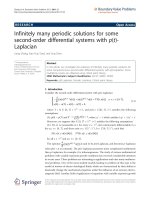
Figure 1: Transmitters and receivers schemes for downlink MC-CDMA.
for two different types of receivers: equal-gain combiner
(EGC) conventional equalizer and a very simple receiver
without channel equalization. Both algorithms operate in the
frequency domain and optimization is done in frequency for
the single-antenna case, and jointly in space and frequency
when considering an antenna array. Moreover, these algo-
rithms are designed using as criterion the minimization of
the transmitted power at the BS, which is a very important
issue for most preequalization algorithms.
The paper is organized as follows. In Section 2,we
present the proposed downlink MC-CDMA system. In
Section 3, we analytically derive the preequalization algo-
rithms for the two receiver configurations which we call con-
strained zero forcing (CZF) and CZF-EGC, respectively. In
Section 4, we present some simulation results obtained with
the CZF and CZF-EGC preequalization techniques in two
different scenarios, beamforming and diversity, and compare
both preequalization schemes against conventional equalizer
techniques such as MRC, EGC, and MMSE. Finally, the main
conclusions are pointed out in Section 5.
2. SYSTEM MODEL
Figure 1 shows the proposed downlink MC-CDMA trans-
mitters and receivers. As presented in Figure 1,foreachuser
k, a complex QPSK data symbol d
k
(k = 1, , K)iscon-
verted from serial to parallel to produce p symbols, d
k,p
(k = 1, , K and p = 0, , P − 1), where P denotes the
number of data symbols transmitted per OFDM symbol.
The data symbols are spread into L chips using the orthog-
onal Walsh-Hadamard code set and scrambled by a pseudo-
random code. We denote the code vector of user k as c
k
=
[c
k,0
, , c
k,L−1
]
T
, where (·)
T
is the transpose operator. Then,
the chips of the data symbols are copied M times in or-
der to obtain L · M versions of the original symbols which
are weighted and transmitted over M antenna branches. The
LM chips for user k and symbol p are weighted by a vector
w
k,p
=
w
T
k,p,1
w
T
k,p,1
··· w
T
k,p,M−1
T
where w
k,p,m
of size L
contains the set of coefficients that weight the chips that go
to antenna m,andthusw
k,p
is of size LM. These weights are
calculated using the CSI according to the criteria presented in
Sections 3.1 and 3.2. After that, the signals of all users on each
subcarrier and antenna branch are added to form the mul-
tiuser transmitted signal. Finally, a guard period (GP) longer
than the channel multipath spread is inserted in the trans-
mitted signal, on each antenna, to avoid intersymbol inter-
ference (ISI).
The transmitted signal, in frequency domain, for a
generic data symbol p is given by
y
p
=
K
k=1
d
k,p
c
k
◦ w
k,p
,(1)
where
c
k
=
c
T
k
, , c
T
k
T
is a column vector of size of L · M
that represents the spreading operation and consists of M
repetitions of the code vector for user k since the same code
is used for all antenna branches, and (◦) means an element-
wise vector product. The vector signal y
p
of length L · M is
mapped to the antenna branch so that the first L elements
are transmitted over the L subcarriers of the OFDM modu-
lation on the first antenna branch, the second L elements to
the second branch, and so on.
The input signal at the generic mobile g,forsymbolp,is
obtained multiplying ( 1) for the channel frequency response
from the BS to the MT of the desired user and adding AWGN
Downlink Preequalization Techniques for TDD MC-CDMA Systems 69
noise:
x
g,p
=
M
m=1
K
k=1
d
k,p
c
k
◦ w
k,p,m
◦ h
g,p,m
+ n
g
,(2)
where h
g,p,m
of size L × 1 is the channel frequency response
between antenna m and MT.
At the receiver side we propose two different receivers:
receiver (a) which is composed just by a single antenna, an
FFT, despreading and descrambling operations, that is, we do
not perform channel equalization, and a conventional EGC
single user receiver (b). For this latter case the weights are
given by
w
r
=
h
∗
|h|
,(3)
that is, we just perform phase equalization.
For receiver (a), the decision variable at the input of the
QPSK demodulator is, for the desired user g and symbol p,
given by
ˆ
d
g,p
= d
g,p
·c
g
M
m=1
w
g,p,m
◦ h
g,p,m
c
H
g
desired signal
+
K
k=1, k=g
d
k,p
· c
k
M
m=1
w
k,p,m
◦ h
g,p,m
c
H
g
MAI
+ n
r
noise
.
(4)
For receiver (b), the decision variable expression is very
similar to (4), but in this case the vector h
g,p,m
is replaced
by
z
g,p,m
=
h
g,p,m
2
+ h
g,p,m
M
i=1, i=m
h
∗
g,p,l
M
m=1
h
g,p,m
,(5)
where (·)
∗
denotes the complex conjugate.
The vector n
r
represents the residual noise samples of ML
subcarriers. The signal of (4) involves the three terms: the de-
sired signal, the MAI caused by the loss of code orthogonality
among the users, and the residual noise after despreading.
3. TRANSMIT PREEQUALIZATION SCHEMES
In this section we analytically derive a space-frequency pree-
qualization algorithm for the two receiver configurations: (a)
and (b). In the latter case, the weights are computed taking
into account that at the receiver we have the EGC combiner.
However, we use the same criterion, zero forcing, in both
preequalization schemes.
The use of preequalization algorithms has two main ad-
vantages: reducing the MAI at MTs by preformatting the sig-
nal so that the received signal at the decision point is free
from interferences and allowing moving the most computa-
tional burden from MT to BS, keeping the MT at a low com-
plexity level. When we use an antenna array at the BS, the
preequalization can be done in both dimensions, space and
frequency. We propose to jointly optimize the user separa-
tion in space and frequency by the use of criteria based on
the decision variable after despreading at the MT. This op-
timization task is performed taking into account the power
minimization at the transmitter side.
3.1. CZF preequalization algorithm
The CZF preequalization algorithm is based on a zero-
forcing criterion, since we put a zero in the MAI term. This
algorithm is designed in order to remove the MAI term of
(4) at all MTs at same time. Furthermore, it takes into ac-
count the transmitted power at BS, the reason we call this
algorithm the CZF.
Applying the zero-forcing criterion to (4), we obtain the
following conditions:
c
g
◦
M
m=1
w
g,p,m
◦ h
g,p,m
c
H
g
= 1,
K
k=1, k=g
c
k
◦
M
m=1
w
k,p,m
◦ h
g,p,m
c
H
g
= 0,
(6)
ensuring that each user receives a sig nal that after despread-
ing is free of MAI. The first term of the right-hand side of
(4) is the desired signal, and has been made, for normaliza-
tion purposes, equal to 1, while the second term represents
the interference caused by other K − 1 users, and according
to the criterion used should be equal to 0.
The interference that the signal of a given user g produces
at another MT k is obtained for a generic data symbol ac-
cording to (4):
MAI(g −→ k) = c
g
M
m=1
w
g,p,m
◦ h
k,p,m
c
H
k
= v
k,g
◦ w
g,p
(7)
with v
k,g
=
c
g
◦
h
k,p,1
h
k,p,2
··· h
k,p,M
◦
c
H
k
.
The weight vector for user g is then obtained by con-
straining the desired signal part of its own decision variable
to 1, while cancelling its MAI contribution all other MTs at
same time. This leads to the following set of conditions:
c
g
◦
M
m=1
w
g,p,m
◦ h
g,p,m
c
H
g
= 1,
c
g
◦
M
m=1
w
g,p,m
◦ h
k,p,m
c
H
k
= 0 ∀k = g.
(8)
Therefore, to compute the weights for user g,wehave
to solve a linear system of K EQUATIONS (constraints) and
70 EURASIP Journal on Wireless Communications and Networking
L · M variables (degrees of freedom) given by
A
g,p
w
g,p
= b,(9)
where A
g,p
is a matrix of size K × ML,givenby
A
g,p
=
h
g,p,1
h
g,p,2
h
g,p,M
v
H
0,g
.
.
.
v
H
g−1,g
v
H
g+1,g
.
.
.
v
H
K−1,g
, b =
1
0
.
.
.
0
. (10)
As pointed above the prefiltering algorithms should take
into a ccount the minimization of the transmitted power.
Therefore, the transmitted power must be minimized un-
der K above constraints. When the number of constraints
equals the number of degrees of freedom, a single solution
exists provided there are no singularities. If however we have
more degrees of freedom than constraints (ML > K), then
signal design can be done to optimize some cost function,
normally, the total transmitted power. The optimization will
be more effective the hig her ML−K is. This optimization can
be solved with the Lagrange multipliers method [10].
The transmitter power p
t
is given by,
p
t
= w
H
g,p
w
g,p
(11)
and consequently we need to minimize the follow ing cost
function with Lagrange multiplier α,
j = w
H
g,p
w
g,p
− αA
g,p
w
g,p
, (12)
computing the gradient vector of j and equating to zero, we
get
∇
w
j = 2 · w
H
g,p
− αA
g,p
= 0 (13)
thus the vector weight is given by
w
g,p
=
1
2
A
H
g,p
α
H
, (14)
and then using this result in (9), we get
α
H
= 2 ·
A
g,p
A
H
g,p
−1
· b. (15)
Finally, replacing α
H
in (14 ), we obtain the CZF-based pre-
filtering vector given by
w
g,p
= A
H
g,P
A
g,p
A
H
g,p
−1
b = A
H
g,p
ψ
−1
g,p
b, (16)
where ψ
g,p
= [A
g,p
A
H
g,p
] is a square and Hermitian matrix of
size K × K.
Observing the last equation, it easy to see that the most
computational intensive task, to calculate the weights, comes
from matrix Ψ
g,p
inversion. However, the size of this matrix
is just K × K independently of the spreading factor and the
number of antennas, which makes this algorithm very attrac-
tive for practical implementations.
3.2. CZF-EGC preequalization algorithm
As referred, for this scheme we also use the zero-forcing cri-
terion, but now to compute the weights, we should take into
account that we have the EGC combiner at receiver side, the
reason we call this algorithm CZF-EGC. When we use the
EGC at receiver side, we increase the complexity as compared
with receiver (a). However, the complexity level is still per-
fectly tolerable for practical implementations. EGC requires
only knowledge about the channel phase.
The interference that the signal of a given user g produces
at another MT k is obtained for a generic data symbol ac-
cording to (4)and(5)by
MAI(g −→ k)
= c
g
M
m=1
w
g,p,m
◦
h
k,p,m
2
+ h
k,p,m
◦
M
i=1, i=m
h
∗
k,p,l
M
m=1
h
k,p,m
c
H
k
= s
k,g
◦ w
g,p
,
(17)
with
s
k,g
=
c
g
◦
h
k,p,1
2
+ h
k,p,1
◦
h
∗
k,p,2
+ ···+ h
∗
k,p,M
h
k,p,1
+ ···+
h
k,p,M
···
h
k,p,M
2
+h
k,p,M
◦
h
∗
k,p,1
+···+ h
∗
k,p,M−1
h
k,p,1
+ ···+
h
k,p,M
◦
c
H
k
.
(18)
The weight vector for user g is also obtained by constrain-
ing the desired sig nal part of its own decision variable to
one while cancelling its MAI contribution to all other MTs
at same time. This leads to the following set of conditions:
c
g
M
m=1
w
g,pm
◦
h
g,p,m
2
+ h
g,p,m
◦
M
i=1, i=m
h
∗
g,p,i
M
m=1
h
g,p,m
c
H
g
=1,
c
g
M
m=1
w
g,p,m
◦
h
k,p,m
2
+ h
k,p,m
·
M
i=1, i=m
h
∗
k,p,i
M
m=1
h
k,p,m
c
H
k
= 0 ∀g = k.
(19)
As the CZF algorithm, the CZF-EGC-based pre-filtering
vector is given by (16). However, the matrix A
g,p
is now given
Downlink Preequalization Techniques for TDD MC-CDMA Systems 71
by
A
g,p
=
h
g,p,1
2
+h
g,p,1
◦
h
∗
g,p,2
+···+h
∗
g,p,M
h
g,p,1
+ ···+
h
g,p,M
···
h
g,p,M
2
+h
g,p,M
◦
h
∗
g,p,1
+···+h
∗
g,p,M−1
h
g,p,1
+ ···+
h
g,p,M
s
H
0,g
.
.
.
s
H
g−1,g
s
H
g+1,g
.
.
.
s
H
K−1,g
.
(20)
From (19) we can see that for the case M = 1 (single
antenna), we obtain an expression very similar to (8)fora
single-antenna case, given by
c
g
· w
g,p
◦
h
g,p
· c
H
g
= 1,
c
g
· w
g,p
◦
h
k,p
· c
H
k
= 0 ∀k = g.
(21)
In this case, the weights are real, because we use the mod-
ulus of the channel frequency response; thus we just equalize
the amplitude at the transmitter whereas the phase is equal-
ized at the receiver side.
4. NUMERICAL RESULTS
To ev aluate the performance of the proposed preequaliza-
tion algorithms, we used a pedestrian Rayleigh fading chan-
nel, whose system parameters are derived from the European
BRAN Hiperlan/2 standardization project [11]. This channel
model has 18 taps, multipath spread of 1.76 µs and coherence
bandwidth approximately equal to 637 KHz.
We extended this time model to a space model in two
different ways: for the diversity case, we assumed that the dis-
tance between antenna elements is large enough to consider
for each user M independent channels, that is, we assume
independent fading processes; for the beamforming case, we
allocated a direction of arrival (DOA) to each path (beam-
forming), with the DOAs randomly chosen within a 120
◦
sector. In this latter case, the BS is equipped with a half-
wavelength-spaced uniform linear array. We considered a DL
synchronized transmission using Walsh-Hadamard spread-
ing sequences of length 32 scrambled by a pseudorandom
code. We used 1024 carriers, a bandwidth equal to 100 MHz,
and a carrier frequency equal 5.0 GHz. The duration of the
GP is 20% of the total OFDM symbol duration. The channel
is considered to be constant during an OFDM symbol.
The simulations were carried out to assess the perfor-
mance of the CZF and CZF-EGC algorithms in the two dif-
ferent scenarios presented above, and to compare against the
performance achieved with conventional frequency equaliza-
tion receivers, such as MRC, EGC, and MMSE. For a better
M = 1
M = 1
M = 2
M = 8
M = 4
CZF
CZF-EGC
EGC
MRC
MMSE
AWGN
0 2 4 6 8 10121416182022
Et/No (dB)
10
−4
10
−3
10
−2
10
−1
Average BER
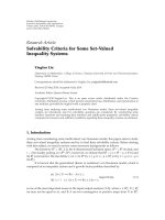
Figure 2: Performance comparison between the CZF, CZF-EGC,
and conventional receivers as function of Et/No, for diversity case.
comparison with a variable number of antennas, the results
have been nor malized, that is, for the case of multiple trans-
mitting antennas, the figures do not take into account the
array gain which is 10 Log(M)indB.
The simulation results for the diversity case are shown in
Figures 2 and 3. The simulations of Figure 2 were run for a
number of users K = 32, that is, a full-load system, and the
metric used is the average bit error rate (BER) as function of
Et/No, the transmitted energy (assuming a normalized chan-
nel) per bit over the noise spectral density. The performance
of the CZF and CZF-EGC algorithms is illustrated for the
cases of M = 1, 2, 4, and 8 transmit antennas. With a sin-
gle antenna at the BS, there is no spatial separation and the
preequalization operation is done only in the frequency di-
mension. As it can be seen from Figure 2, the performance
of the CZF algorithm for a single antenna is modest. At low
values of Et/No, the performance is even worse than with all
single-user conventional detectors, and only for high values
of Et/No the CZF outperforms the conventional MRC equal-
izer. This occurs because for a single antenna and full load
system, we do not have enough degrees of freedom to mini-
mize the tr ansmitted power. The number of degrees of free-
dom is equal to M · L and the number of constraints is K.
Thus, for M = 1andK = L (full-load system), the number
of degrees is equal to the number of constraints. For multi-
ple antennas at BS, it is possible to optimize the preequal-
ization algorithm in both dimensions, space and frequency.
When we use an array of 2, 4, and 8 antennas, the perfor-
mance of the CZF algorithm is much better than all single-
user conventional equalizers for any Et/No value. We can see
that with 4 and 8 antennas, the performance is very close
to the one obtained with the Gaussian channel. As it can be
seen from Figure 2, the performance of the CZF-EGC algo-
rithm for single antenna outperforms the MRC, EGC, MMSE
72 EURASIP Journal on Wireless Communications and Networking
Et/No = 10 dB
M = 1
M = 1
M = 2
M = 4
CZF
CZF-EGC
EGC
MRC
MMSE
1 5 10 15 20 26 32
Number of users
10
−4
10
−3
10
−2
10
−1
Average BER
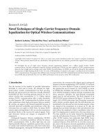
Figure 3: Performance comparison between the CZF, CZF-EGC
and conventional receivers as function of number of users, for di-
versity case.
conventional equalizers, and the CZF. This occurs because,
as can be seen f rom (21), with single antennas the CZF-EGC
weights are real. Thus, we just perfor m a preequalization am-
plitude operation at the transmission side while the phase
equalization is done at the receiver. In the case of CZF, we
perform the amplitude and phase equalization at transmis-
sion side. For two antennas, the performance of the CZF-
EGC is slightly better than the one of the CZF algorithm,
while for a number of antenna elements greater than four,
the performance of both algorithms is nearly identical.
The simulations leading to Figure 3 were run for Et/No =
10 dB, and the metric used is the average BER as a function
of number of the users and considers the cases of a single-,
two-, and four-antenna elements. From this figure we can
see that for a single antenna, the CZF algorithm performance
outperforms the one obtained with conventional receiver
equalizers for number of users up to 16 (half load).
Beyond this point the performance degradation rapidly
increases with the number of users. This arises because for a
single antenna the difference between the number of degrees
of freedom and constraints tends to zero as the number of
users increases. When the number of antennas increases, the
performance of the CZF improves, because we increase the
number of degrees of freedom keeping the number of con-
straints. From Figure 3 we can see that for M = 2and4,and
the CZF gives better results than all conventional equalizers,
even for full load system. Concerning CZF-EGC algorithm,
we can see that performance is much better that all conven-
tional receiver equalizers even for single antenna. When we
increase the number of antenna elements, the performance
of the CZF-EGC tends to the CZF performance, even for full-
load system.
K = 32
M = 1
M = 1
M = 2
M = 8
M = 4
CZF
CZF-EGC
EGC
MRC
MMSE
MRC single user
0 2 4 6 8 10121416182022
Et/No (dB)
10
−4
10
−3
10
−2
10
−1
Average BER
Figure 4: Performance comparison between the CZF, CZF-EGC
and conventional receivers as function of Et/No, for beamforming
case.
The simulation results for the beamforming case are
shown in Figure 4, where the simulation metrics and param-
eters other than the channels correlation are identical to the
ones considered for Figure 2. The results show that the CZF
algorithm outperforms all the conventional equalizers, ex-
cept for the single-antenna case (with loads close to full) as
happened with the diversity scenario. From this figure we can
see that the performance of the CZF with two antennas is
worse than the conventional MMSE combiner. With eight-
antenna elements, the CZF performance is very close to the
performance of the MRC single user. The performance of the
CZF-EGC with single antenna is very good as compared with
all conventional equalizers and CZF. For the single-antenna
case we have the same number of degrees of freedom for both
algorithms, but for CZF-EGC case we just perform the am-
plitude equalization at transmitter side, while for CZF we
perform amplitude and phase equalization. We can even see
that the performance is similar to the one obtained with CZF
algorithm for four antennas. The performance of the CZF-
EGC for four and eight antennas is very close to the one ob-
tained with CZF.
5. CONCLUSIONS
We proposed space-frequency preequalization techniques for
downlink TDD MC-CDMA, using antenna arrays at BS, for
two different receivers: the conventional EGC and a simple
despread receiver without channel equalization. We analyti-
cally derived the proposed preequalization algorithms, based
on a constrained zero-forcing criterion. The performance
was assessed for either of the diversity and beamforming sce-
narios and compared against one of conventional receivers.
Downlink Preequalization Techniques for TDD MC-CDMA Systems 73
The results have shown that a considerable MAI reduction is
obtained with the CZF-EGC technique, and with CZF when
an antenna array is used at BS. For a single antenna, the per-
formance of the CZF-EGC outperforms the CZF for a full-
load case, while with multiple antennas the performances
are very similar. Both techniques allow a significant improve-
ment of the user capacity and move the most-demanded pro-
cessing task from BS to MT, keeping this one as simple as
possible.
ACKNOWLEDGMENTS
The work presented in this paper was supported by the
European project IST-2001-32620, MATRICE project, and
Portuguese Foundation for Science and Technology (FCT)
through project POSI/CPS/46701/2002 and a grant to the
first author.The work presented in this paper was published
in part at VTC FALL 2003 and MC-SS 2003 proceedings.
REFERENCES
[1] S. Abeta, H. Atarashi, and M. Sawahashi, “Forward link ca-
pacity of coherent DS-CDMA and MC-CDMA broadband
packet wireless access in a multi-cell env ironment,” in Proc.
IEEE Vehicular Technology Conference (VTC ’00), vol. 5, pp.
2213–2218, Boston, Mass, USA, September 2000.
[2] IST MATRICE project, web site: .
[3] S. Hara and R. Prasad, “Overview of multicarrier CDMA,”
IEEE Communications Magazine, vol. 35, no. 12, pp. 126–133,
1997.
[4] H. Atarashi, N. Maeda, S. Abeta, and M. Sawahashi, “Broad-
band packet wireless access based on VSF-OFCDM and
MC/DS-CDMA,” in Proc. The 13th IEEE International Sym-
posium on Personal, Indoor and Mobile Radio Communications
(PIMRC ’02), vol. 3, pp. 992–997, Lisboa, Portugal, September
2002.
[5] B. R. Vojcic and W. M. Jang, “Transmitter precoding in syn-
chronous multiuser communications,” IEEE Trans. Commu-
nications, vol. 46, no. 10, pp. 1346–1355, 1998.
[6] A. Silva and A. Gameiro, “Pre-filtering techniques using an-
tenna arrays for downlink TDD MC-CDMA systems,” in Proc.
4th International Workshop on Multi-Carrier Spread-Spectrum
(MC-SS ’03),Oberpfaffenhofen, Germany, September 2003.
[7] A. Silva and A. Gameiro, “Transmit space-frequency prefilter-
ing technique for downlink TDD MC-CDMA systems,” in
Proc. IEEE Semiannual Vehicular Technology Conference,Or-
lando, Fla, USA, October 2003.
[8] A. F. Naguib, A. J. Paulraj, and T. Kailath, “Capacity improve-
ment with base-station antenna arrays in cellular CDMA,”
IEEE Trans. Vehicular Technology, vol. 43, no. 3, pp. 691–698,
1994.
[9] C. K. Kim and Y. S. Cho, “Performance of a wireless MC-
CDMA system with an antenna array in a fading channel: re-
verse link,” IEEE Trans. Communications,vol.48,no.8,pp.
1257–1261, 2000.
[10] S. Haykin, Adaptative Filter Theory, Prentice-Hall, Upper Sad-
dle River, NJ, USA, 3rd edition, 1996.
[11] J. Medbo and P. Schramm, “Channel models for Hiper-
lan/2 in different indoor scenarios,” ETSI/BRAN document
No. 3ERI085b, March 1998.
Ad
˜
ao Silva received his B.S. and M.S. de-
grees from the University of A veiro, both
in electronics and telecommunications, in
1999 and 2002, respectively. He is cur-
rently working towards the Ph.D. degree at
the same university. He became an Invited
Assistant Professor in the Department of
Electronics and Telecommunications of the
University of Aveiro, and a Researcher at
the Instituto de Telecomunicac¸
˜
oes, P
´
olo de
Aveiro. His main interests lie in signal processing techniques and
space-time coding for wireless communications. His current re-
search activities involve preequalization and space-time-frequency
algorithms for the broadband component of 4G systems.
At
´
ılio Gameiro received his Licenciatura
(five-year course) and his Ph.D. from the
University of Aveiro in 1985 and 1993,
respectively. He is currently a Professor
in the Depart ment of Electronics and
Telecommunications of the University of
Aveiro, and a researcher at the Instituto de
Telecomunicac¸
˜
oes, P
´
olo de Aveiro, where he
is a head of group. His main interests lie
in signal processing techniques for digital
communications and communication protocols. Within this re-
search line, he has done work for optical and mobile commu-
nications, at either the theoretical or experimental level, and has
published over 100 technical papers in international journals and
conferences. His current research activities involve space-time-
frequency algorithms for the broadband component of 4G systems
and joint design of layers 1 and 2.