Báo cáo hóa học: " Modelling and Optimising TinyTP over IrDA Stacks" pdf
Bạn đang xem bản rút gọn của tài liệu. Xem và tải ngay bản đầy đủ của tài liệu tại đây (685.47 KB, 12 trang )
EURASIP Journal on Applied Signal Processing 2005:1, 45–56
c
2005 Hindawi Publishing Corporation
Modelling and Optimising TinyTP over IrDA Stacks
A. C. Boucouvalas
Microelectronics and Multimedia Communications Research Centre, School of Design, Engineering and Computing,
Bournemouth University, Fern Barrow, Poole, Dorset BH12 5BB, UK
Email: tboucouv@bour nemouth.ac.uk
Pi Huang
Microelectronics and Multimedia Communications Research Centre, School of Design, Engineering and Computing,
Bournemouth University, Fern Barrow, Poole, Dorset BH12 5BB, UK
Email: phuang@bourn emouth.ac.uk
Received 29 March 2004; Revise d 20 August 2004
TinyTP is the IrDA transport layer protocol for indoor infrared communications. For the first time, this paper presents a math-
ematical model for TinyTP over the IrDA protocol stacks taking into account the presence of bit errors. Based on this model,
we carry out a comprehensive optimisation study to improve system performance at the transport layer. Four major parame-
ters are optimised for maximum throughput including TinyTP receiver window, IrLAP window and frame size, as well as IrLAP
turnaround time. Equations are derived for the optimum IrLAP window and frame sizes. Numerical results show that the sys-
tem throughput is significantly improved by implementing the optimised parameters. The major contribution of this work is
the modelling of TinyTP including the low-layer protocols and optimisation of the overall throughput by appropriate parameter
selection.
Keywords and phrases: IrDA, TinyTP, IrLAP, transport layer protocol, optimisation.
1. INTRODUCTION
Indoor infrared data communications, based on the Infrared
Data Association (IrDA) standards, have become widely
available on a large number of portable devices ranging from
mobile phones and digital cameras to laptops and printers
[1]. Infrared communication is a n excellent choice for effec-
tive, inexpensive and hig h-speed short-range wireless com-
munications. The low-level IrDA protocols including phys-
ical (IrPHY) [2, 3], link access (IrLAP) [4], and link man-
agement (IrLMP) protocols [5] are adopted as industry stan-
dards and implemented on the products. Tiny transport pro-
tocol (TinyTP) is an optional IrDA layer, whereas it is so im-
portant and widely implemented that it is generally consid-
ered a required layer [6].
In [7], an IrLAP model is presented as the first sig-
nificant work on the IrDA link layer. Subsequently, many
link layer performance evaluations and improvements have
also been undertaken recently to address different infrared
link issues including the impact on link throughput of de-
vice processing speed [8] and future increase in data rates
[9]. All the previous publications focus on link layer perfor-
This is an open-access article distributed under the Creative Commons
Attribution License, which permits unrestricted use, distribution, and
reproduction in any medium, provided the original work is properly cited.
mance by assuming data always available of infinite size and
a single application ready to transmit. However, upper lay-
ers (e.g., TinyTP) in practice offer finite-size packets to the
link layer at specific time periods due to protocol behaviour
and limited buffer size. TinyTP also allows multiple appli-
cations to operate the IrDA link concurrently. It is there-
fore of interest to examine the system throughput at TinyTP
level.
The rest of this paper is organised as follows. First, we
briefly describe the IrDA protocol stacks. Then, the details of
TinyTP functionality are described. We subsequently develop
a mathematical model for TinyTP which allows derivation
of throughput taking into account the lower IrDA protocol
stack. The TinyTP receiver w indow size and the IrLAP win-
dow and frame sizes are optimised for the maximum system
throughput for any g iven bit error rate (BER). Finally, the
suitable IrLAP turnaround time is investigated for 16 Mbps
links.
2. IrDA PROTOCOL STACKS
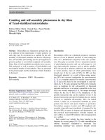
The IrDA protocol stack illustrated in Figure 1 is the layered
set of protocols particularly aimed at point-to-point infrared
communications and the applications needed in that envi-
ronment. A brief description of the IrDA protocol stack is as
follows.
46 EURASIP Journal on Wireless Communications and Networking
Serial infrared
(SIR)
Fast infrared
(FIR)
Very fast infrared
(VFIR)
IrDA link access protocol (IrLAP)
IrLMP multiplexer (LM-MUX)
TinyTP
IrLMP
information access
service
(LM-IAS)
IrCOMM
IrOBEX
IrLAN
Applications
Figure 1: IrDA protocol stacks.
2.1. IrDA physical layer
The IrDA physical layer defines a directed half-duplex se-
rial infrared communications link established through free
space to facilitate point-to-point communication. Framing
data such as beginning- and end-of-frame flags (BOFs and
EOFs), and cyclic redundancy checks (CRCs) are also con-
sidered to be part of the physical layer. Transceivers with data
rates of 4 and 16 Mbps have a 6-byte physical header for each
IrLAP frame [2, 3].
2.2. IrDA link access protocol
IrLAP is the link access layer and it is based on the high-level
data link control (HDLC) protocol. By using mechanisms in-
cluding retransmission, low-level flow control and error de-
tection, IrLAP provides reliable data transfer. IrLAP trans-
mits data in the form of frames with maximum length of l
LAP
and organises the transmission using go-back-N (GBN) er-
ror recovery. As the physical layer defines a half duplex link,
IrLAP manages the transmission by assigning primary and
secondary stations. The primary station initiates transfers to
the secondary station and manages the link. When the pri-
mary completes the transmission of a window size N, infor-
mation (I-) frames that can be sent before link turnaround,
it then sets the poll (P) bit in the last I-frame to signal link
turnaround and request the acknowledgement from the sec-
ondary. Once P bit is set, the secondary can start sending
data. It changes P bit to 0 to turnaround the link when it
finishes transmission. Referring to standards [3, 4], the win-
dow size and frame size range from 1 to 127 and f rom 128 bit
to 16384 bit, respectively, IrLAP adds a 3-byte header to each
frame.
2.3. IrDA link management protocol
IrLMP provides support for multiple software applica-
tions or entities to operate independently and concurrently,
sharing the single link provided by IrLAP between the
transceivers [5]. To realise the multiplexing, IrLMP assigns
each application a unique link service access point (LSAP)
address. IrLMP delivers upper-layer data segments based on
the first-in first-out (FIFO) queuing [5]. We assume that the
multiple application channels equally share the infrared link
in this paper. After the connection initialisation, IrLMP adds
a 2-byte header to the upper-layer packet providing the LSAP
address for the sender and receiver.
3. TinyTP
TinyTP (TTP) is a light transport protocol serving as a flow
control mechanism to work with IrLMP [6]. Even though Ir-
LAP provides reliable data transfer, TinyTP is still important
to ensure the end-to-end data delivery for the application.
This is due to the possible deadlock problem of multiplexed
channels introduced by IrLMP multiplexer (LM-MUX). Re-
liance on I rLAP to provide flow control for a multiplexed
channel can result in deadlocks if the consumption of data
from one multiplexed channel is dependent on data flowing
in an adjacent multiplexed channel. Conversely, if inbound
data on a multiplexed channel cannot be consumed and the
underlying IrLAP connection cannot b e flow controlled due
to the possibility of deadlock, inbound data (freshly arrived
or buffered) must be discarded in the event of buffer exhaus-
tion. Unfortunately, this reduces the reliable delivery service
provided by IrLAP to a best-effort deliv ery service provided
by LM-MUX. To overcome this problem TinyTP provides
two functions:
(i) segmentation and reassembly;
(ii) flow control on a per-LMP-connection (per-channel)
basis.
For TinyTP, the entire data packet from upp er layers can
be segmented and reassembled in service data units (SDUs).
The maximum SDU size is negotiated at the TinyTP/IrLMP
connection establishment. One SDU has to fit within one Ir-
LAP frame. Maximum TinyTP SDU size l
TTP
therefore has
to satisfy the condition l
TTP
≤ l
LAP
− l
LMP
− l
TTP
,wherel
LMP
and l
TTP
stand for the headers of IrLMP and TinyTP. In this
paper, we consider the challenge of having large application
files to transmit. To make TinyTP efficient, we assume l
TTP
is
setatitsmaximumvaluel
TTP
= l
LAP
− l
LMP
− l
TTP
.
To perform flow control, TinyTP maintains a value of re-
ceiver window (w) for each TinyTP channel. The value of w
is decided by the TinyTP buffer size of the communication
peer. The sender will send SDU if w>0andsubtractw by
1. Therefore, each TinyTP application can send maximum w
SDU without receiving acknowledgement but it has to stop
while w = 0. w is updated by the TinyTP acknowledgement
from its peer. We assume every TinyTP application has the
same value of w in this paper.
Each TinyTP service access point (TTPSAP) is accessi-
ble through one and only one LSAP of LM-MUX. A TTP-
SAP is identified by the address of the LSAP (provided in
IrLMP header) through which it is accessed. After TinyTP
Modelling and Optimising TinyTP over IrDA Stacks 47
IrLAP information frames (T
send
)
IrLAP buffer
IrLAP
t
ta
w
new
NX segments
MUX
IrLMP
If w>0
w − 1
TinyTP
···
TinyTP T
x
queuing buffer
TinyTP
segmentation
Source 1 ··· Source N
TinyTP + IrLAP ack
IrLAP buffer
IrLAP
t
ta
(CRC)
w
new
NX segments
DeMUX
IrLMP
w
new
= w
old
− X
X
T
ta
w × l
TTP
···
TinyTP R
x
buffer
TinyTP
X
w
new
= w
old
+ X
X
w
new
= w
old
+ X
Sink 1 ··· Sink N
Figure 2: TinyTP data transmission.
Table 1: Parameters used in the modelling.
Symbol Parameter description Unit
C Link data rate bps
B Number of TinyTP connections —
p
b
Link BER —
p Frame error rate —
N Maximum IrLAP window size (number of frames) —
w TinyTP receiver window —
l
LAP
Maximum IrLAP frame data length bit
l
TTP
Maximum TinyTP seg ment size, l
TTP
= l
LAP
− l
LMP
− l
TTP
bit
l
PHY
PHYheader:BOF+EOF+CRC 48bits
l
LAP
IrLAP header 24 bits
l
LMP
IrLMP header 16 bits
l
TTP
TinyTP header 8 bits
t
I
Transmission time of an information (I-)frame s
t
S
Transmission time of a supervision (S-)frame s
t
ack
Time to transmit an IrLAP acknowledgement packet s
t
ta
IrLAP minimum turnaround time s
t
Fout
IrLAP F-timer time-out period s
T
ta
Time for TinyTP to process the received s egments and prepare the acknowledgement s
connection initialisation, TinyTP adds 1 byte of header car-
rying information including its own buffer size and the seg-
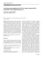
mentation status. A flow chart of the data transmission with
multiple TinyTP connections is provided in Figure 2.
4. MATHEMATICAL MODELLING
The mathematical model assumes large application files (e.g.,
mp3, movie clip) to be sent from the primary to the sec-
ondary. TinyTP segments therefore are always at the maxi-
mum size (l
TTP
= l
LAP
− l
LMP
− l
TTP
) to accommodate the ap-
plication data. The “connected” TinyTP segments (excluding
the connection establishment and termination segments) are
considered in the derivation. Therefore, IrLMP and TinyTP
have fixed headers of 2 bytes and 1 byte, respectively. We
make use of Table 1 for symbol details.
4.1. IrLAP modelling
Correct IrLAP frame transmissions following an erroneous
frame transmission in the same IrLAP window are consid-
ered out of sequence and have to be retr ansmitted (GBN).
48 EURASIP Journal on Wireless Communications and Networking
0123456P
t
ta
S7F
t
ack
t
send
t
I
(a)
0123456P
t
ta
S2F
t
ack
t
send
3456
(b)
0123456P
t
ta
S2F
t
ack
S0P
t
S
t
Fout
t
send
456
(c)
Figure 3: (a) Error-free transmission of an IrLAP window, (b) retransmission frames due to error frame at frame 3, and (c) retransmitted
frames and F-timer delay due to frame error at I=3 and I=7 (P-bit lost).
Based on the IrLAP model given in [7], in this section, we
will derive the average time to successfully transmit one Ir-
LAP window at a given BER. Due to the small size of the
IrLAP supervision (S-) and acknowledgement (ack-) frames,
we consider the IrLAP windows to be transmission error free.
According to the IrLAP standard [4], IrLAP link parameters
t
s
, t
I
, t
ack
, p,andt
Fout
aredefinedasfollows:
t
s
=
l
LAP
+ l
PHY
C
, t
I
=
l
LAP
+ l
LAP
+ l
PHY
C
, t
ack
= t
s
,
p = 1 −
1 − p
b
l
LAP
+l
LAP
+l
PHY
, t
Fout
= t
I
+2t
ta
.
(1)
Both supervision and ack-frame have the same length which
is the same as the physical and IrLAP header. If the last frame
of the window is in error which causes P-bit loss, neither pri-
mary nor secondar y is able to send data. F-timer t
Fout
is the
final bit timer used by the primary to limit the time it waits
for a frame from the secondary. After t
Fout
has expired, the
primary will send a supervision frame to the secondary ac-
knowledging the link turnaround. Figure 3 illustrates the Ir-
LAP operation in detail.
The average time to successfully transmit one IrLAP win-
dow consists of the time for frame transmissions, acknowl-
edgements and retransmissions, as well as delays for re-
versing the link t
ta
and timer time outs t
Fout
. As shown in
Figure 3, the average time to transmit one IrLAP window
with length of A fr ames is given as follows:
t
A
= At
I
+ p
t
Fout
+ t
s
+ t
ack
+2t
ta
. (2)
The probability of having error/errors in an IrLAP window
with A frames is
p
1
= 1 − (1 − p)
A
. (3)
Due to the small value of p, p
1
can be approximated as
p
1
= 1 − (1 − p)
A
≈ 1 − (1 − Ap) = Ap. (4)
While error/errors occur in transmitting the IrLAP window
with probability p
1
, due to the randomness of error occur-
rence, it is sufficient to assume that on average the error oc-
curs in the middle of the w indow, and a retransmission will
trigger to recover the error with window length of 0.5A.If
further error/errors occur in the retransmission with prob-
ability of p
2
= p
1
(1 − (1 − p)
0.5A
) ≈ 0.5A
2
p
2
, a nother re-
transmission window is needed with window length of half
the previous, that is, 0.25A, and so on. When the retransmis-
sion window is less than 1, we consider the whole window has
been successfully transmitted. By including the first window
Modelling and Optimising TinyTP over IrDA Stacks 49
transmission and all the retransmissions, the average time to
successfully transmit the IrLAP window is given:
T
send
(A) = t
A
+ p
1
1
2
At
I
+ p
t
Fout
+ t
s
+ t
ack
+2t
ta
+ ···+ p
X
1
2
X
At
I
+ p
t
Fout
+ t
s
+ t
ack
+2t
ta
=
1+
1
2
Ap + ···+
1
2
(1/2)X(X+1)
A
X
p
X
At
I
+
1+Ap + ···+
1
2
(1/2)X(X−1)
A
X
p
X
×
p
t
Fout
+ t
s
+ t
ack
+2t
ta
=
1+
A
i=1
1
2
(1/2)i(i+1)
(Ap)
i
At
I
+
1+Ap +
X
i=2
1
2
(1/2)i(i−1)
(Ap)
i
×
p
t
Fout
+ t
s
+ t
ack
+2t
ta
,
(5)
where X is an integer representing the number of retransmis-
sions (X =log
2
A). X satisfies the length of the retr ansmis-
sion w indow to be no less than 1 (1/2
X
· A ≤ 1).
4.2. Derivation of TinyTP throughput
Before deriving TinyTP throughput, we first discuss two
TinyTP parameters T
ack
and T
ta
. According to the standard
[6], TinyTP acknowledgement needs only to provide the up-
dated secondary receiver window size. Therefore, the sec-
ondary simply sends the TinyTP header l
TTP
as the TinyTP
ack. By including the headers of the other layers, the trans-
mission time of the TinyTP acknowledgement is given by
T
ack
=
l
Phy
+ l
LAP
+ l
LMP
+ l
TTP
C
. (6)
The time to hold the TinyTP segments in the buffer (T
ta
)
is the time from passing the IrLAP frames to IrLMP to the
time the TinyTP gets acknowledgement ready at the sec-
ondary. As shown in Figure 2, T
ta
includes the time to pro-
cess and strip the headers all the way up to TinyTP, the time
to process the TinyTP segments and drain the TinyTP buffer,
as well as preparing TinyTP ack and adding the headers of
other layers. For different applications, the time to process
the TinyTP segments (T
p
)isdifferent. In this paper, we as-
sume that the IrDA device uses 8-bit processor and each 8-bit
data takes average 2-CPU cycles. As T
p
is the major fac tor of
T
ta
, we assume that T
ta
≈ T
p
:
T
ta
≈ T
p
=
2Al
TTP
8v
=
Al
TTP
4v
,(7)
where A is the incoming IrLAP window size and v is the pro-
cessor speed in Hz.
When a TinyTP receiver window size w is allocated for
each B TinyTP connections, the IrDA receiver has to assign a
TinyTP buffer with size of B × w × l
TTP
. Given the fact that
memory is highly constrained for resource-limited wireless
device, such devices often cannot afford large memory size
for TinyTP. For a given maximum IrLAP window size N,
three possible scenarios by implementing different receiver
window size are investigated as follows, w here B denotes the
number of TinyTP connections. We assume the TinyTP con-
nections equally share the link as IrLMP delivers data based
on FIFO queuing.
4.2.1. Bw ≤ N
The TinyTP transmission model is illustrated in Figure 4 by
mapping TinyTP segments into IrLAP frames. In Figure 4,
parameters w = 2, B = 2, and N ≥ 4 are employed which
satisfy Bw ≤ N. The IrLAP window will be always less than
four due to the w constraint. As the time to prepare the
TinyTP acknowledgement packet T
ta
depends on the CPU
speed of the receiver, it is normally much longer than IrDA
link turnaround t
ta
and the time to transmit the IrLAP ack
packet. Thus, it is sufficient to assume T
ta
>t
ta
+ t
ack
.After
IrLAP successfully delivers the IrLAP frames, the secondary
has to wait T
ta
before the TinyTP acks get ready. Since two
TinyTP connections are considered, the secondary needs to
send two TinyTP acks. Then, following the same routine
another window w i ll be sent from the primary. Therefore,
we only need to consider one window transmission for the
TinyTP throughput derivation.
As shown in Figure 4, and using (5), the average time for
one TinyTP window transmission T
1
is given by
T
1
= T
send
(Bw)+T
ta
+ BT
ack
+ t
ta
,(8)
where w is the receiver window size and B is the number of
TinyTP connections.
The TinyTP throughput which is defined as information
bits per second is
D =
Bw × l
TTP
T
1
. (9)
4.2.2. N<Bw<2N
The TinyTP transmission model is illustrated in Figure 5.In
Figure 5, w = 3, N = 4, and B = 2 are used, which sat-
isfy N<Bw<2N. The first TinyTP window has 4 seg-
ments and makes use of maximum IrLAP window length.
Since the secondar y is fed by 4 TinyTP segments and has no
time to process, the secondary will send 2 TinyTP acks to give
the information of available buffer size for each application.
In this case, the secondary acknowledges the primary with
w1 = w2 = 1 (available buffer size subtracted from the in-
50 EURASIP Journal on Wireless Communications and Networking
Application
TinyTP
service
access point
TinyTP
segment
Receiver
window size
+
TinyTP
overhead
+
IrLMP
overhead
IrLAP
station1 (R
x
)
IrLAP
station2 (T
x
)
T
1
T
send
(Bw)
t
ack
t
ta
t
ta
t
ta
T
ta
T
ack
T
ack
t
ta
ack
1
ack
2
A
A
LAP1 LAP2 LAP3 LAP4 LAP3 LAP4 LAP5
···
9bytes
2bytes
1byte
w1 = 1 w2 = 1 w1 = 0 w2 = 0 w1 = 2 w2 = 2 w1 = 1
TTP1
SAP1
TTP1
SAP2
TTP2
SAP1
TTP2
SAP2
TTP3
SAP1
···
TTPSAP1 TTPSAP2
APP1 APP2
Figure 4: TinyTP transmission model when Bw ≤ N, initial state: w1 = w2 = 2, where A is the IrLAP acknowledgement and ack is the
TinyTP acknowledgement.
Application
TinyTP
service
access point
TinyTP
segment
Receiver
window size
+
TinyTP
overhead
+
IrLMP
overhead
IrLAP
station1 (R
x
)
IrLAP
station2 (T
x
)
T
2
T
send
(N) T
send
(Bw − N)
t
ack
t
ta
t
ta
t
ta
t
ack
ack
1
ack
2
T
ack
T
ack
t
ta
t
ta
t
ack
ack
1
ack
2
T
ack
T
ack
t
ta
AA
N
Bw − N
A
LAP1 LAP2 LAP3 LAP4 LAP3 LAP4 LAP5 LAP6 LAP7
···
9bytes
2bytes
1byte
w1 = 2 w2 = 2 w1 = 1 w2 = 1 w1 = 1 w2 = 1 w1 = 0 w2 = 0 w1 = 2 w2 = 2 w2 = 1
TTP1
SAP1
TTP1
SAP2
TTP2
SAP1
TTP2
SAP2
TTP3
SAP1
TTP3
SAP2
TTP4
SAP1
···
TTPSAP1 TTPSAP2
APP1 APP2
Figure 5: TinyTP transmission model when N<Bw<2N, initial state: w1 = w2 = 3.
coming segments, 3−2 = 1). The primary is then able to send
2 segments in the second window. Assuming the 4 TinyTP
segments of the last window have been processed and con-
sumed, each of the receiver window equals to 2 (3 − 1 = 2).
The secondary then acknowledges with w1 = w2 = 2. As
the same process will be repeated, we only need to consider
two window transmissions for deriving the TinyTP through-
put.
Modelling and Optimising TinyTP over IrDA Stacks 51
Application
TinyTP
service
access point
TinyTP
segment
Receiver
window size
+
TinyTP
overhead
+
IrLMP
overhead
IrLAP
station1 (R
x
)
IrLAP
station2 (T
x
)
T
3
T
send
(N) T
send
(N)
t
ack
t
ta
ack
1
ack
2
T
ack
T
ack
t
ta
t
ta
t
ta
t
ack
ack
1
ack
2
t
ta
t
ack
T
ack
T
ack
t
ta
A
A
NN
A
LAP1 LAP2 LAP3 LAP4
LAP5 LAP6 LAP7 LAP8 LAP7 LAP8 LAP9 ···
9bytes
2bytes
1byte
w1 = 4 w2 = 4 w1 = 3 w2 = 3 w1 = 3 w2 = 3 w1 = 2 w2 = 2 w1 = 1 w2 = 1 w1 = 3 w2 = 3 w1 = 2
TTP1
SAP1
TTP1
SAP2
TTP2
SAP1
TTP2
SAP2
TTP3
SAP1
TTP3
SAP2
TTP4
SAP1
TTP4
SAP2
TTP5
SAP1
···
TTPSAP1 TTPSAP2
APP1 APP2
Figure 6: TinyTP transmission model when w ≥ 2N, initial state: w1 = w2 = 5.
The average transmission times for the first and the sec-
ond IrLAP windows is
T
send
(N) =
1+
X
i=1
1
2
(1/2)i(i+1)
(Np)
i
Nt
I
+
1+Np+
X
i=2
1
2
(1/2)i(i−1)
(Np)
i
×
p
t
Fout
+ t
s
+ t
ack
+2t
ta
,
T
send
(w − N)
=
1+
X
i=1
1
2
(1/2)i(i+1)
(w − N)p
i
(w − N)t
I
+
1+(w − N)p +
X
i=2
1
2
(1/2)i(i−1)
(w − N)p
i
×
p
t
Fout
+ t
s
+ t
ack
+2t
ta
.
(10)
With the aid of Figure 5 and by u sing (5), the average time
for one TinyTP window transmission T
2
is
T
2
= T
send
(N)+BT
ack
+ t
ta
+ T
send
(Bw − N)+BT
ack
+ t
ta
= T
send
(N)+T
send
(Bw − N)+2BT
ack
+2t
ta
.
(11)
TinyTP throughput is
D
=
Bw × l
TTP
T
2
. (12)
4.2.3. Bw ≥ 2N
The TinyTP transmission model in this case is illustrated in
Figure 6.InFigure 6, w = 5, N = 4, and B = 2areused,
which satisfy Bw ≥ 2N. The first TinyTP window has 4 seg-
ments which make use of maximum IrLAP window length.
The secondary acknowledges with w1 = w2 = 3(avail-
able buffer size subtracted from the incoming segments,
5 − 2 = 3). The primary is then allowed to send another 4
segments in the second window. Assuming the TinyTP seg-
ments of last window have been processed and consumed,
the secondary then acknowledges with w1 = w2 = 3
(5 − 2 = 3), and so on. Therefore, we only need to consider
one window transmission for deriving the TinyTP through-
put.
From Figure 6, each of the IrLAP windows has a length of
N. The average transmission time for the first and the second
IrLAP windows is
T
3
= T
send
(N)+BT
ack
+ t
ta
. (13)
The TinyTP throughput is given by
D =
Nl
TTP
T
3
. (14)
TinyTP throughput efficiency (TPE) is given by
TPE =
D
C
. (15)
52 EURASIP Journal on Wireless Communications and Networking
w = 5(Bw ≤ N)
w = 15 (N<Bw<2N)
w = 30 (Bw ≥ 2N)
1.0E − 08 1.0E − 07 1.0E − 06 1.0E − 5
BER
0.3
0.4
0.5
0.6
0.7
0.8
0.9
1
Overall TPE
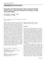
Figure 7: Overall TinyTP throughput efficiency comparison using
different receiver window sizes w. Overall TinyTP throughput is the
aggregate throughput of B channels, and IrLAP window N = 20.
5. TinyTP THROUGHPUT ANALYSIS
Equations (9), (12), and (14) reveal the parameters TinyTP
throughput depends on. In this section, in order to provide
a suitable design guideline for IrDA devices, we carry out
an inclusive throughput analysis. We compare the through-
put by implementing different TinyTP buffer sizes for var-
ious BERs. Subsequently, we examine the effect of IrLAP
turnaround time on the throughput. Finally, we investigate
the effect of the processor speed.
5.1. Effect of TinyTP receiver window size (w)
In Figure 7, TinyTP TPEs are compared by implementing
different receiv er window sizes w. We fix the maximum Ir-
LAP window and frame size at N = 20 and l = 16 kbit, re-
spectively. The following parameters are used for this figure:
C = 16 Mbps, v = 10 MHz, t
ta
= 10
−4
second, and B = 2.
Unless otherwise specified, the same values of C, v, t
ta
,and
B are implemented throughout this paper. The throughput
efficiencies are plotted against the BER in the range of 10
−5
to 10
−8
.
As shown in Figure 7, all of the three TPE deteriorate
with the increase in the BER. In the case of w = 15 and 30,
the system obtains much better TPEs than when w = 5es-
pecially for low BER (TPE > 0.8). The TPE for w = 30 is
slightly better than for w = 15. The g raph shows that the
system achieves the best throughput for any BER by using a
receiver window size at least twice the maximum IrLAP win-
dow size (Bw ≥ 2N ). However, a good TinyTP throughput
level is also reached by using w = 15 (N<Bw<2N). There-
fore, a receiver window size in the range of N<Bw<2N
obtains good system performance as well as requiring rela-
tively smaller buffer size.
l = 16 Kbits, N = 50 (Bw N )
l = 16 Kbits, N = 20 (Bw 2N)
l = 2Kbits, N = 30 (N<Bw<2N)
l = 16 Kbits, N = 30 (N<Bw<2N)
l = 2Kbits, N = 50 (Bw N )
l = 2Kbits, N = 20 (Bw 2N )
1.0E − 08 1.0E − 07 1.0E − 06 1.0E − 5
BER
0.4
0.5
0.6
0.7
0.8
0.9
1
Overall TPE
Figure 8: TinyTP TPE comparison using different receiver window
sizes w (w = 20).
5.2. Effect of IrLAP window size (N) and frame size (l)
In Figure 8, TinyTP TPEs are compared by implementing
different IrLAP windows and frame sizes. The TinyTP re-
ceiver window size is set to w = 20. Throughput efficiency
is plotted against the BER in the range of 10
−5
to 10
−8
.All
the TPE curves decrease with the increasing BER. The system
achieves better TPE by using large frame size (l = 16 Kbit) a t
low BER, however, at the high BER, the system obtains better
TPE by implementing small frame size (l = 2 Kbit). For the
same window size, the crossing points of the two curves that
represent different frame size l implying a better throughput
may be achieved by appropriately adjusting of window and
frame sizes.
5.3. Effect of processor speed (v)
We assume here that the TinyTP segments in the previous
window have been processed for the case of N<Bw<2N
and Bw ≥ 2N. This assumption holds true when the ex-
treme condition T
ta
≤ 3t
ta
+2t
ack
+ BT
ack
+ t
I
is satis-
fied. To fulfill this condition, processor speed has to be at
least as fast as CNl
TTP
/4(3Ct
ta
+2Ct
ack
+ CBT
ack
+ l
LAP
). For
instance, for a 1− Mbps IrDA link with N = 4, l
LAP
=
16 kbit, t
ta
= 10
−3
s, and B = 2, processor speed v has
to be at least 0.8 MHz to satisfy the condition. If v<
CNl
TTP
/4(3Ct
ta
+2Ct
ack
+ CBT
ack
+ l
LAP
), TinyTP through-
put will be deteriorated due to the extra time needed to wait
for the TinyTP segment processing. Based on our TinyTP
model, Figure 9 shows the effect of processing speed when
Bw ≤ N. We obtain the result by using the following pa-
rameters: N = 20, l = 16Kbit, and w = 5. The TPEs are
plotted in three different BERs against the processor speed in
the range of 10
5
to 10
8
Hz.
Modelling and Optimising TinyTP over IrDA Stacks 53
BER = 10e − 7
BER = 10e − 6
BER = 10e − 5
1.0E + 05 1.0E + 06 1.0E + 07 1.0E + 08
Processor speed v (Hz)
0
0.2
0.4
0.6
0.8
Overall TPE
Figure 9: Effect of processor speed on TPE when Bw ≤ N in differ-
ent BER (w = 5andN = 20).
All three TPE curves increase with the processor speed
until saturation for v>10
7
Hz = 10 MHz. Because T
ta
be-
comes larger than t
ta
+ t
ack
when v>10 MHz, the secondary
will wait for t
ta
+t
ack
instead of T
ta
before sending the TinyTP
acks. Therefore, the processor speed will not benefit from the
system throughput when v>10 MHz. However, the TPE in-
creases significantly with the processor speed up to 10 MHz.
Therefore, v = 10 MHz is a suitable processing speed for the
16 Mbps IrDA links.
6. THROUGHPUT OPTIMISATIONS
6.1. Optimum TinyTP receiver window size w
As shown in Figure 7, the system achieves its best perfor-
mance when Bw ≥ 2N because it takes full advantage of
the IrLAP maximum window size. However, the system will
reach the same throughput as Bw = 2N when Bw > 2N.Be-
cause the throughput is also constrained by the IrLAP win-
dow size N, it will not be improved by a receiver window size
larger than 2N. Therefore, a receiver window size of w = 2N
can always achieve the best throughput even only one TinyTP
connection is running. As shown in Figure 7, good TinyTP
throughput is also obtained by using a receiver window size
of N<Bw<2N. For the memory scarce devices, in or-
der to improve system performance and resource require-
ment, TinyTP can use a receiver window size in the range
of N<Bw<2N, as this range achieves good throughput as
well as requiring relatively small buffer size.
6.2. Optimum IrLAP window size N and frame size l
LAP
As shown in Figure 8, if IrLAP window and frame sizes can be
optimised, we can achieve better throughput at the TinyTP
level. In [10, 11], optimisation equations of the IrLAP pa-
rameters are presented to maximise the IrLAP throughput.
However, when considering TinyTP performance optimisa-
tion, due to the constraint of receiver window size, the opti-
misations at IrLAP level are not suitable for TinyTP. In or-
der to maximise the TinyTP throughput for any given re-
ceiver window size and BER, IrLAP parameters are optimised
in this section. In situations where it is convenient to opti-
mise only one variable, either N or l
LAP
, we obtain maximum
TinyTP throughput by using optimum values for l
LAP
or N,
respectively. However the best TinyTP throughput would be
obtained when both N and l
LAP
are simultaneously optimised
with BER.
6.2.1. Optimum window or frame size for maximum
TinyTP throughput
6.2.1.1. Bw ≤ N
Because each TinyTP connection cannot send more than w
segments before receiving an acknowledgement, IrLAP win-
dow size always equals Bw, as shown in Figure 4. Therefore,
in this c ase, we only need to optimise IrLAP frame size l
LAP
for a fixed N with value of Bw.
By calculating ∂D/∂l
LAP
= 0for(9), which is a function
of l
LAP
, the optimum value of l
LAP
for any fixed N is derived.
After some calculations and careful approximations, the op-
timum equation for l
LAP
is derived:
l
opt
=
1
Bw
2
t
ack
+ BT
ack
+3t
ta
C
p
b
. (16)
6.2.1.2. N<Bw<2N
In this case, both N and l
LAP
are adjustable. N is limited in the
range from N to 2N. It is possible to maximise throughput
by fixing either N or l
LAP
and optimising the other. By taking
∂D/∂N = 0for(12), the optimum value of N for any fixed
l
LAP
is derived. Also, for fixed N,optimuml
LAP
value is de-
rived by taking the derivative of D, ∂D/∂l
LAP
= 0. After some
calculus and approximations, the optimum equations for N
and l
LAP
are given by
N
opt
=
Bw
2
, (17)
l
opt
= 2
t
ack
+3t
ta
+ BT
ack
C
2N
2
− 2BwN + B
2
w
2
p
b
.
(18)
6.2.1.3. Bw ≥ 2N
By using the same approach as given above, optimum equa-
tions for N and l
LAP
are given by
N
opt
=
2
t
ack
+3t
ta
+ BT
ack
C
(l + l
)
2
p
b
, (19)
l
opt
=
2
Nl
+
t
ack
+3t
ta
+ BT
ack
C
N
2
p
b
,
(20)
where l
= l
PHY
+ l
LAP
.
54 EURASIP Journal on Wireless Communications and Networking
6.2.2. Simultaneous optimum window and frame size
for maximum TinyTP throughput
In this case, both window and frame size can be simulta-
neously adjusted. The maximum possible throughput per-
formance can be achieved. In order to derive optimum N
and l values, first we fix l
LAP
to derive optimum N by tak-
ing ∂D/∂N = 0. Then, the derived optimum N equation
(l
LAP
dependent) is substituted into the throughput equa-
tion. Throughput D becomes a function of frame size l
LAP
for optimum N values. By taking ∂D/∂l
LAP
= 0, optimum
l
LAP
equation is derived. This essentially derives the condi-
tions for ∂D
b
/∂N = ∂D
b
/∂l
LAP
= 0. Finally, by substituting
optimum l
LAP
equation back to optimum N equation (l
LAP
dependent), we can derive the optimum equation N.
6.2.2.1. Bw ≤ N
As described in Section 6.2.1.1, IrLAP window size is fixed at
Bw. Therefore, only IrLAP frame size l
LAP
is needed to opti-
mise for throughput which is given in (16).
6.2.2.2. N<Bw<2N
In 6.2.1.2, optimum N in equation (17)isalreadyl
LAP
inde-
pendent. Therefore, we only need to substitute (17) into the
throughput equation (12)toderiveoptimuml
LAP
.Optimum
N and l
LAP
in this case are given by
N
opt
=
Bw
2
,
l
opt
=
2
Bw
t
ack
+3t
ta
+ BT
ack
C
p
b
.
(21)
6.2.2.3. Bw ≥ 2N
Finally, simultaneously optimum N and l
LAP
equation are
given by
N
opt
=
2
t
ack
+3t
ta
+ BT
ack
CY p
b
4l
+4l
p
b
Y + p
2
b
Yl
2
− p
2
b
Y
2
l
, (22)
l
opt
=
4l
+4l
p
b
Y + p
2
b
Yl
2
− p
2
b
Y
2
l
Yp
2
b
, (23)
where Y =
2(t
ack
+3t
ta
+ BT
ack
)C/p
b
.
For low BER, l
opt
should be ver y large and takes values
larger than 16 kbits, values not allowed by IrDA specification
[4]. In practice, therefore, it is restricted to using both ap-
proaches for optimum IrLAP parameters. We use approach
6.2.1.3, (20), to obtain N
opt
in low BER for fixed maximum
value l = 16 Kbits, until the calculated l
opt
is less than 16 Kbits
(∼ BER = 5.7 ∗ 10
6
from (22) using B = 2, v = 10 Mz and
t
ta
= 10
−4
s). Thereafter for higher BER, approach 6.2.2.3,
(22)and(23), is implemented to obtain optimum through-
put.
In order to examine the accuracy of the optimum equa-
tions derived in this section, we compare the results obtained
Exact (Bw N)
Exact (N<Bw<2N)
Exact (Bw 2N)
Equation (Bw N)
Equation (N<Bw<2N)
Equation (Bw 2N)
1.0E − 08 1.0E − 07 1.0E − 06 1.0E − 05
BER
0.4
0.5
0.6
0.7
0.8
0.9
1
Overall TPE
Figure 10: TinyTP TPE using optimum IrLAP window and frame
size, and TinyTP receiver window w = 20.
from the equations with the results obtained from exact nu-
merical methods. In Figure 10, the overall TPE is plotted
against BER in the range from 10
−5
to 10
−8
by implement-
ing the simultaneously optimised N and l. The correspond-
ing optimised IrLAP window and frame size used are plotted
in Figure 11.
As shown in Figure 11, the optimum frame sizes l
opt
are
fixed at 16 Kbit in the low BER and then drop down signifi-
cantly with the increasing BER. The exact and equation ap-
proaches for the optimum values have only small differences.
For all of the three cases, the curves representing two di ffer-
ent approaches follow the same shape and are very close to
each other. The optimum window sizes N
opt
have exactly the
same values of 20 for either exact or using the equation re-
sults when N<Bw<2N. N
opt
also shows very good agree-
ment for Bw ≥ 2N, especially in the low BER.
In Figure 10, the throughput efficiencies gradually de-
crease when the BER increases. Comparing the optimum
TPE results obtained from the equations with results ob-
tained from exact numerical methods, they show very good
agreement for all three cases. Moreover, the system always
acquires its optimum throughput in the case of Bw > 2N.
Therefore, for a given size of TinyTP receiver window, N
opt
should always satisfy the condition Bw > 2N and be calcu-
lated from (19)and(22) for the corresponding BER. A com-
parison between Figures 8 and 10 shows that optimisations
of IrLAP window and frame size are necessary since the per-
formance is significantly improved at TinyTP level when the
optimum values are used.
6.3. Optimum IrLAP turnaround time
Inordertoexaminetheeffect of IrLAP turnaround time, op-
timum N and l are considered. As shown in the previous sec-
tion, N
opt
should always satisfy the condition Bw > 2N for
Modelling and Optimising TinyTP over IrDA Stacks 55
Exact (Bw N)
Exact (N<Bw<2N)
Exact (Bw 2N)
Equation (Bw N)
Equation (N<Bw<2N)
Equation (Bw 2N)
1.0E − 08 1.0E − 07 1.0E − 06 1.0E − 05
BER
0
2
4
6
8
10
12
14
16
18
×10
3
Optimum IrLAP frame size
(a)
Exact (N<Bw<2N)
Exact (Bw 2N)
Equation (N<Bw<2N)
Equation (Bw 2N)
1.0E − 08 1.0E − 07 1.0E − 06 1.0E − 05
BER
0
5
10
15
20
25
Optimum IrLAP window size
(b)
Figure 11: The corresponding optimum IrLAP window and frame size to Figure 10.
BER = 1.0E − 07
BER = 1.0E − 06
BER = 1.0E − 05
1.0E − 02 1.0E − 03 1.0E − 04 1.0E − 05
IrLAP turnaround t
ta
0
0.2
0.4
0.6
0.8
1
overall TPE
Figure 12: Effect of IrLAP turnaround time on TinyTP TPE, w =
20, optimum N and l.
the maximum throughput. Therefore, we only need to con-
sider the case of Bw > 2N.InFigure 12, TinyTP TPEs are
plotted against IrLAP turnaround time in the range of 10
−5
to 10
−2
second. The TPEs are compared by implementing
three different BERs. The receiver window size is fixed at 20.
As shown in Figure 12, the TPEs for low BER are better than
in the high BER for the same IrLAP turnaround time. With
t
ta
in the range of t
ta
< 10
−4
s = 0.1 millisecond, the three
TPEs only increase slightly. However, the TPEs decrease sig-
nificantly when t
ta
increases above 0.1 millisecond. By con-
sidering the system performance and hardware requirement
tradeoff, it can be seen that an IrLAP turnaround time at the
level of 10
−4
second is a suitable parameter for the 16- Mbit
IrDA links.
7. CONCLUSIONS
In this paper, we derive a comprehensive model for the IrDA
TinyTP performance in the presence of BER by consider-
ing multiple IrLMP connections and taking the underlying
IrDA protocol stacks into account. Based on the model, the
throughput efficiencies are compared by implementing dif-
ferent receiver window size, and IrLAP window and frame
sizes. The results show that the system always achieves its
best performance when Bw
≥ 2N and can be maximised
by optimising IrLAP window and frame sizes for any given
BER. Subsequently, an inclusive study for parameter opti-
misations is carried out for the system. Several optimisation
equations for IrLAP window and frame sizes are derived and
later validated in the simulations. Finally, the effect of IrLAP
turnaround time on the throughput is examined. An IrLAP
turnaround time of the order in 10
−4
second is a suitable pa-
rameter for 16− Mbps links. By comparing the results, we
can see that significant improvements on the throughput are
achieved by applying the optimised parameters.
56 EURASIP Journal on Wireless Communications and Networking
REFERENCES
[1] S. Williams, “IrDA: past, present and future,” IEEE Pers. Com-
mun., vol. 7, no. 1, pp. 11–19, 2000.
[2] IrDA, “Serial infrared physical layer specification,” version 1.1,
October 1995.
[3] IrDA, “Serial infrared physical layer specification for 16 Mb/s
addition (VFIR),” errata to version 1.3, January 1999.
[4] IrDA, “Serial infrared link access protocol,” version 1.1, June
1996.
[5] IrDA, “Serial infrared link management protocol,” version
1.1, January 1996.
[6] IrDA, “Tiny transpor t protocol,” version 1.1, October 1996.
[7] P. Barker, A. C. Boucouvalas, and V. Vitsas, “Performance
modelling of the IrDA infrared wireless communications pro-
tocol,” International Journal of Communications Systems, vol.
13, no. 7-8, pp. 589–604, 2000.
[8] P. Chatzimisios and A. C. Boucouvalas, “IrLAP IrDA protocol
throughput dependence on processor speed,” in Proc. Inter-
national Symposium on CSNDSP, pp. 272–275, Staffordshire
University , Staffordshire, UK, July 2002.
[9] A. C. Boucouvalas and V. Vitsas, “100 Mb/s IrDA protocol
performance evaluation,” in Proc. International Conference on
Wireless and Optical Communications (WOC ’01), pp. 49–57,
Banff, Canada, June 2001.
[10] V. Vitsas and A. C. Boucouvalas, “Simultaneous optimisa-
tion of window and frame size for maximum throughput
IrDA links,” Electronics Letters, vol. 37, no. 16, pp. 1042–1043,
2001.
[11] V. Vitsas and A. C. Boucouvalas, “Optimization of IrDA IrLAP
link access protocol,” IEEE Transactions on Wireless Commu-
nications, vol. 2, no. 5, pp. 926–938, 2003.
A. C. Boucouvalas has worked at GEC
Hirst Research Centre, and became a Group
Leader and a Divisional Chief Scientist un-
til 1987 when he joined Hewlett Packard
(HP) Laboratories as a Project Manager. At
HP Labs, he worked in the areas of optical
communication systems, optical networks,
and instrumentation, until 1994, when he
joined Bournemouth University. In 1996, he
became a Professor in multimedia commu-
nications, and in 1999 the became the Director of the Microelec-
tronics and Multimedia Research Centre. His current research in-
terests span the fields of wireless communications, optical fibre
communications and components, multimedia communications,
and human-computer interfaces, where he has published over 200
papers. He has contributed to the formation of IrDA as an indus-
try standard and he is now a Member of the IrDA Architectures
Council. He is a Fellow of the Royal Society for the encourage-
ment of Arts, Manufacturers and Commerce (FRSA) and a Fel-
low of IEE (FIEE). In 2002 he became a Fellow of the Institute
of Electrical and Electronic Engineers (FIEEE) for contributions
to optical fibre components and optical wireless communications.
He is a Member of the New York Academy of Sciences, and the
Association for Computing Machinery (ACM). He is an Editor
of numerous journals and in the organising committees of many
conferences.
Pi Huang received the B.S. degree in elec-
trical and electronic engineering from the
University of Central Lancashire, UK, in
2001, and the M.S. degree in telecom-
munications from the University Col-
lege London, UK, in 2002. He is cur-
rently pursuing his Ph.D. degree in wire-
less personal area communication network
with the Microelectronics and Multimedia
Communications Research Centre (M
2
C),
Bournemouth University, UK. His research focuses on perfor-
mance modelling and analysis as well as discrete-event simulation
of wireless communication protocols and wireless communication
networks. He has published over 10 papers in the areas of wireless
communications. Mr. Huang is a Student Member of IEEE and IEE.