Báo cáo hóa học: " Flexible Transmission Scheme for 4G Wireless Systems with Multiple Antennas" potx
Bạn đang xem bản rút gọn của tài liệu. Xem và tải ngay bản đầy đủ của tài liệu tại đây (927.03 KB, 15 trang )
EURASIP Journal on Wireless Communications and Networking 2005:3, 308–322
c
2005 Franc¸ois Horlin et al.
Flexible Transmission Scheme for 4G Wireless
Systems with Multiple Antennas
Franc¸ois Horlin
Wireless Research, Interuniver sity Micro-Electronics Center (IMEC), Kapeldreef 75, B-3001 Leuven, Belgium
Email:
Frederik Petr
´
e
Wireless Research, Interuniver sity Micro-Electronics Center (IMEC), Kapeldreef 75, B-3001 Leuven, Belgium
Email:
Eduardo Lopez-Estraviz
Wireless Research, Interuniver sity Micro-Electronics Center (IMEC), Kapeldreef 75, B-3001 Leuven, Belgium
Email:
Frederik Naessens
Wireless Research, Interuniver sity Micro-Electronics Center (IMEC), Kapeldreef 75, B-3001 Leuven, Belgium
Email:
Liesbet Van der Perre
Wireless Research, Interuniver sity Micro-Electronics Center (IMEC), Kapeldreef 75, B-3001 Leuven, Belgium
Email: vdper
Received 15 October 2004; Revised 11 May 2005
New air interfaces are currently being developed to meet the high requirements of the emerging wireless communication systems.
In this context, the combinations of the multicarrier (MC) and spread-spectrum (SS) technologies are promising candidates. In
this paper, we propose a generic transmission scheme that allows to instantiate all the combinations of or t hogonal frequency-
division multiplexing (OFDM) and cyclic-prefixed single-carrier (SC) modulations with direct-sequence code-division multiple
access (DS-CDMA). The generic transmission scheme is extended to integrate the space-division multiplexing (SDM) and the
orthogonal space-time block coding (STBC). Based on a generalized matrix model, the linear frequency-domain minimum mean
square error (MMSE) joint detector is derived. A mode selection strategy for up- and downlink is advised that efficiently trades
off the cost of the mobile terminal and the achieved performance of a high-mobility cellular system. It is demonstrated that
an adaptive transceiver that supports the proposed communication modes is necessary to track the changing communication
conditions.
Keywords and phrases: code-division multiple access, OFDM, cyclic-prefix single carrier, space-division multiplexing, space-time
block coding, joint detection.
1. INTRODUCTION
Because of the limited frequency bandwidth, on the one
hand, and the potential limited power of terminal stations,
on the other hand, spectral and power efficiency of fu-
ture systems should be as high as possible. New air inter-
faces need to be developed to meet the new system require-
This is an open access article distributed under the Creative Commons
Attribution License, which permits unrestricted use, distribution, and
reproduction in any medium, provided the original work is properly cited.
ments. Combinations of the multicarrier (MC) and spread-
spectrum (SS) modulations, named multicarrier spread-
spectrum techniques, could b e interesting candidates. They
might benefit from the main advantages of both MC and SS
schemes such as high spectral efficiency, multiple-access ca-
pabilities, narrowband interference rejection, simple one-tap
equalization, and so forth.
Cellular systems of the third generation are based
on the recently emerged direct-sequence code-division
multiple-access (DS-CDMA) technique [1]. Intrinsically,
DS-CDMA has interesting networking abilities. First, the
Flexible Transmission Scheme for 4G Wireless Systems 309
communicating users do not need to be time synchronized
in the uplink. Second, soft handover is supported between
two cells making use of different codes at the base stations.
However, the system suffers from intersymbol interference
(ISI) and multiuser interference (MUI) caused by multipath
propagation, leading to a high loss of performance.
The use of the orthogonal frequency-division multiplex-
ing (OFDM) modulation is widely envisaged for wireless
local area networks [2]. At the cost of the addition of a
cyclic prefix, the time dispersive channel is seen in the fre-
quency domain as a set of parallel independent flat sub-
channels and can be equalized at a low-complexity. An al-
ternative approach to OFDM, that benefits from the same
low complexity equalization property, is single-carrier block
transmission (SCBT), also known as single-carrier (SC) with
frequency-domain equalization. Since the SCBT technique
benefits from a lower p eak-to-average power ratio (PAPR),
[3] encourages the use of SCBT in the uplink and OFDM in
the downlink in order to reduce the constraints on the analog
front end and the processing complexity at the terminal.
There are potential benefits in combining OFDM (or
SCBT) and DS-CDMA. Basically the frequency-selective
channel is first equalized in the frequency domain using the
OFDM modulation technique. DS-CDMA is applied on top
of the equalized channel, keeping the interesting orthogo-
nality properties of the codes. The DS-CDMA signals are
either spread across the OFDM carriers (referred to as in-
trablock spreading) leading to multicarrier CDMA (MC-
CDMA) [4, 5, 6, 7], or across the OFDM blocks (referred to
as interblock spreading) leading to multicarrier block-spread
CDMA (MCBS-CDMA) [8, 9, 10, 11]. The SCBT counter-
parts named here single-carrier CDMA (SC-CDMA) a nd
single-carrier block-spread CDMA (SCBS-CDMA) have also
been proposed in [12, 13, 14, 15], respectively. The differ-
ent flavors to mix the MC and SS modulations complement
each other and allow to make an efficient tradeoff between
the spectral and p ower efficiency according to the user re-
quirements, channel propagation characteristics (time and
frequency selectivity), and terminal resources. For example,
it has been recently proposed, in [16] for the downlink, and
in [17] for the uplink, to perform a two-dimensional spread-
ing (combination of MC-CDMA with MCBS-CDMA) in or-
der to cope with the time and frequency selectivity of the
channels. The chips of a given symbol are mapped on adja-
cent channels where the fading coefficients are almost con-
stant so that the orthogonality properties of the codes are
preserved and a low-complexity single-user detector can be
used.
To meet the data rate and quality-of-service require-
ments of future broadband cellular systems, their spectral
efficiency and link reliability should be considerably im-
proved, which cannot be realized by using traditional single-
antenna communication techniques. To achieve these goals,
multiple-input multiple-output (MIMO) systems, which de-
ploy multiple antennas at both ends of the wireless link, ex-
ploit the extra spatial dimension, besides the time, frequency,
and code dimensions, which allows to significantly increase
the spectral efficiency and/or to significantly improve the
link reliability relative to single-antenna systems [18, 19, 20].
MIMO systems explicitly rely on the fac t that the channels
created by the additional spatial dimension are independent
from each other. This is approximately true in rich scattering
environments. However, when the channels are correlated,
the gain obtained by the use of multiple antennas is lim-
ited. Until very recently, the main focus of MIMO research
was on single-user communications over narrowband chan-
nels, thereby neglecting the multiple-access aspects and the
frequency-selective fading channel effects, respectively.
First, if the multiantenna propagation channels are suf-
ficiently uncorrelated, MIMO systems can create N
min
par-
allel spatial pipes, which allows to realize an N
min
-fold ca-
pacity increase, where N
min
= min {N
T
, N
R
} (N
T
and N
R
denote the number of transmit and receive antennas, resp.)
is called the spatial multiplexing gain [ 18, 19, 20]. Specifi-
cally, space-division multiplexing (SDM) techniques exploit
this spatial multiplexing gain, by simultaneously transmit-
ting N
min
independent information streams at the same fre-
quency [21, 22]. In [23], SDM is combined with SC-CDMA
to increase the data rate of multiple users in a broadband cel-
lular network.
Second, MIMO systems can also create N
T
N
R
indepen-
dently fading channels between the transmitter and the re-
ceiver, which allows to realize an N
T
N
R
-fold diversity in-
crease, where N
T
N
R
is called the multiantenna diversity gain.
Specifically, space-time coding (STC) techniques exploit di-
versity and coding gains, by encoding the transmitted signals
not only over the temporal domain but also over the spa-
tial domain [24, 25, 26]. Space-time block coding (STBC)
techniques, introduced in [25]forN
T
= 2 transmit anten-
nas, and later generalized i n [26]foranynumberoftrans-
mit antennas, are particularly appealing because they facili-
tate maximum-likelihood (ML) detection with simple linear
processing. However, these STBC techniques have originally
been designed for frequency-flat fading channels exploiting
only multiantenna diversity of order N
T
N
R
. Therefore, time-
reversal (TR) STBC techniques, originally proposed in [27]
for single-carrier serial transmission, have been combined
with SCBT in [28, 29] for signaling over frequency-selective
fading channels. In [30, 31], the TR-STBC technique of [28]
is combined with SC-CDMA to improve the performance
of multiple users in a broadband cellular network. Although
this technique enables low-complexity chip equalization in
the frequency domain, it does not preserve the orthogonality
among users, and hence, still suffers from multiuser inter-
ference. The space-time coded multiuser transceiver of [32],
which combines the TR-STBC technique of [29] with SCBS-
CDMA, preserves the orthogonality among users as well
as transmit streams, regardless of the underlying multipath
channels. This al lows for deterministic ML user separation
through low-complexity code-matched filtering as well as de-
terministic ML tr a nsmit stream separation through linear
processing. Another alternative to remove MUI determinis-
tically in a space-time coded multiuser setup [33, 34]com-
bines generalized multicarrier (GMC) CDMA, originally de-
veloped in [35], with the STBC techniques of [26] but imple-
mented on a per-carrier basis.
310 EURASIP Journal on Wireless Communications and Networking
Intrablock
spreading
Interb lock
spreading
IFFT redundancy
s
m
[j] θ
m
˜
s
m
[j]
N
inter
c
m
[n]
˜
x
m
[n]
F
H
Q
x
m
[n]
T
u
m
[n]
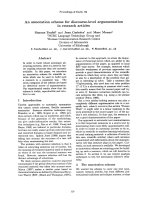
Figure 1: Single-antenna transmitter model.
We propose a transmission chain composed of generic
blocks and able to instantiate all the communication modes
combining OFDM/SCBT and DS-CDMA as special cases. In
contrast with the t ransceiver proposed in [35, 36, 37] that
relies on a sharing of the set of carriers to retain the orthog-
onality between the users, our transmission scheme relies on
orthogonal CDMA, and thus inherits the nice advantages of
CDMA related to universal frequency reuse in a cellular net-
work, like increased capacity and simplified network plan-
ning. Furthermore, the focus is especially put on the com-
munication modes emerging in the standards. We demon-
strate the rewarding synergy between existing and evolving
MIMO communication techniques and our generic trans-
mission technique, which allows to increase the spectral ef-
ficiency and to improve the link reliability of multiple users
in a broadband cellular network. Considering realistic prop-
agation channels, we also advise a strategy for mode selec-
tion according to the communication conditions, making an
efficient tradeoff between the desired performance and the
required computational complexity.
The paper is organized as follows. In Section 2, the
generic transmission scheme is presented that can capture
the standard emerging communication modes as special
cases. It is shown how the MC and SC modes can be instan-
tiated. Section 3 is devoted to the extension of the transmis-
sion scheme introduced in Section 2 to multiple-antenna sys-
tems. Both SDM and STBC multiple-antenna techniques are
considered. A low-complexity minimum mean square error
(MMSE) receiver is designed in Section 4 based on a gener-
alized matr ix model. Finally, a strategy for communication
mode selection is proposed in Section 5, based on the evalu-
ation of the cost and performance of each mode in a highly
mobile cellular environment.
In the sequel, we use single- and double-underlined let-
ters for the vectors and matrices, respectively. Matrix I
N
is the
identity matrix of size N and matrix 0
M×N
is a matrix of zeros
of size M × N.Theoperators(·)
∗
,(·)
T
,and(·)
H
denote, re-
spectively, the complex conjugate, transpose, and transpose
conjugate of a vector or a matrix. The operator ⊗ is the Kro-
necker product between two vectors or matrices. We index
the transmitted block sequence by i, the MIMO coded block
sequence and the intrablock chip block sequence by j,and
the interblock chip block sequence by n.
2. SINGLE-ANTENNA GENERIC
TRANSMISSION SCHEME
The transmission scheme for the mth user (m = 1, , M)
is depicted in Figure 1. Since we focus on a sing le-user
transmission, the transmission scheme applies to both the
up- and downlink. In the uplink, the different user’s signals
are multiplexed at the receiver, after propagation through
their respective multipath channels. In the downlink, the dif-
ferent user signals are multiplexed at the tr ansmitter, before
the inverse fast Fourier transform (IFFT) oper a tion.
The transmission scheme comprises four basic opera-
tions: intrablock spreading, interblock spreading, IFFT, and
adding transmit redundancy. The symbols s
m
[ j]arefirst
serial-to-parallel converted into blocks of B symbols, lead-
ing to the sequence s
m
[ j]:= [s
m
[ jB] ···s
m
[( j +1)B − 1]]
T
.
The blocks s
m
[j] are linearly precoded with a Q × B (Q ≥ B)
matrix, θ
m
, which possibly introduces some redundancy and
spreads the symbols in s
m
[ j] with length-Q codesasfollows:
˜
s
m
[j]:= θ
m
· s
m
[j]. (1)
We refer to this first operation as intrablock spreading, since
the information symbols s
m
[ j] are spread within a single pre-
coded block
˜
s
m
[j]. The precoded block sequence
˜
s
m
[ j]is
then block spread with the elements c
m
[n] of a length-N
inter
code sequence, leading to N
inter
successive chip blocks:
˜
x
m
[n]:=
˜
s
m
[ j]c
m
n − jN
inter
,(2)
where j =n/N
inter
. We refer to this second operation as
interblock spreading, since the information symbols s
m
[ j]are
spread along N
inter
different chip blocks. The third operation
involves the transformation of the frequency-domain chip
block sequence
˜
x
m
[n] into the time-domain chip block se-
quence:
x
m
[n]:= F
H
Q
·
˜
x
m
[n], (3)
where F
H
Q
is the Q×Q IFFT matrix. Finally, the K×Q (K ≥ Q)
transmit matrix T possibly adds some transmit redundancy
to the time-domain chip blocks:
u
m
[n]:= T · x
m
[n]. (4)
With K
= Q + L denoting the total block length T = T
cp
:=
[I
T
cp
, I
T
Q
]
T
,whereI
cp
consists of the last L rows of I
Q
, T
adds redundancy in the form of a length-L cyclic prefix (cp).
The chip block sequence u
m
[n] is parallel-to-serial converted
into the scalar sequence [u
m
[nK]···u
m
[(n +1)K − 1]]
T
:=
u
m
[n], and transmitted over the air at a r a te 1/T
c
(T
c
stands
for the chip duration).
In the following, we will detail how our generic transmis-
sion scheme instantiates different communication modes,
and, thus, supports different emerging communication stan-
dards. We distinguish between the MC modes, on the one
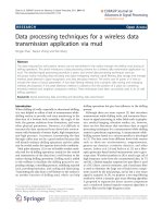
hand, and the SC modes, on the other hand. In Figure 2, the
principle of CDMA spreading in two possible dimensions is
illustrated.
Flexible Transmission Scheme for 4G Wireless Systems 311
Code
Spreading
factor
Frame block
Subchannel
(MC carrier frequency or SC time instant)
···
(a)
Code
Spreading
factor
Frame block
Subchannel
(MC carrier frequency or SC time instant)
(b)
Figure 2: (a) Intrablock s preading pattern (MC/SC-CDMA). (b) Interblock spreading pattern (MCBS/SCBS-CDMA).
2.1. Instantiation of the multicarrier modes
The MC modes always comprise the IFFT operation, and add
transmit redundancy in the form of a cyclic prefix (T = T
cp
).
The MC modes comprise MC-CDMA and MCBS-CDMA as
particular instantiations of the generic transmission scheme.
2.1.1. MC-CDMA
As we have indicated in the introduction, MC-CDMA first
performs classical DS-CDMA symbol spreading, followed by
OFDM modulation, such that the information symbols are
spread across the different subcarriers located at different fre-
quencies and characterized by a different fading coefficient
[4, 5, 6]. With Q = BN
intra
and N
intra
the intrablock spreading
code length, the Q × B intr ablock spreading matrix θ
m
= β
m
spreads the chips across the subcarriers, where the mth user’s
Q × B spreading matrix β
m
is defined as
β
m
:= I
B
⊗ a
m
,(5)
with a
m
:= [a
m
[0] ···a
m
[N
intra
− 1]]
T
the mth user’s N
intra
×
1 code vector. The interblock spreading operation is dis-
carded by setting N
inter
= 1. Since intrablock spread-
ing does not preserve the orthogonality among users in a
frequency-selective channel, MC-CDMA requires advanced
multiuser detection for uplink reception in the base station,
and frequency-domain chip equalization for downlink re-
ception in the mobile station. MC-CDMA has been proposed
as a candidate air interface for future broadband cellular sys-
tems [7].
2.1.2. MCBS-CDMA
The MCBS-CDMA transmission scheme is the only MC
mode that comprises the interblock spreading operation
N
inter
> 1. Since the CDMA spreading is applied on each
carrier independently, which can be seen as a constant fad-
ing channel if the propagation environment is static, MCBS-
CDMA retains the orthogonality among users in both up-
and downlink [11]. Hence, it has the potential to convert a
difficult multiuser detection problem into an equivalent set
of simpler and independent single-user equalization prob-
lems. However, it will be shown in Section 5 that the perfor-
mance of MCBS-CDMA is hig h ly degraded under medium-
to-high mobility conditions since the orthogonality between
the users is lost in that case. In case no channel state in-
formation (CSI) is available at the transmitter, it performs
linear precoding to robustify the transmitted signal against
frequency-selective fading. In case CSI is available at the
transmitter, it allows to optimize the transmit spectrum of
each user separately through adaptive power and bit load-
ing. Note that classical MC-DS-CDMA can be seen as a spe-
cial case of MCBS-CDMA, because it does not include linear
precoding, but, instead, only relies on bandwidth-consuming
forward error correction (FEC) coding to enable frequency
diversity [8, 10, 38].
2.2. Instantiation of the single-carrier modes
The SC modes employ a fast Fourier transform (FFT) as part
of the intrablock spreading operation to annihilate the IFFT
operation. For implementation purposes, however, the IFFT
is simply removed (and not compensated by an FFT ), in
order to minimize the implementation complexity. The SC
modes rely on cyclic prefixing (T
= T
cp
) to make the chan-
nel appear circulant. The SC modes comprise SC-CDMA
and SCBS-CDMA as particular instantiations of the generic
transmission scheme.
2.2.1. SC-CDMA
The SC-CDMA transmission scheme, which combines SCBT
with DS-CDMA, can be interpreted as the SC counterpart
of MC-CDMA [12, 13]. This mode is captured through our
general transmission scheme, by setting Q = BN
intra
.The
intrablock spreading matrix θ
m
= F
Q
· β
m
,withβ
m
de-
fined in (5), performs symbol spreading on the B informa-
tion symbols, followed by an FFT operation to compensate
312 EURASIP Journal on Wireless Communications and Networking
d
m
1
[i]
d
m
N
T
[i]
MIMO
coding
.
.
.
.
.
.
θ
m
θ
m
N
inter
N
inter
c
m
[n]
c
m
[n]
F
H
Q
F
H
Q
T
T
u
m
1
[n]
u
m
N
T
[n]
s
m
1
[j]
˜
s
m
1
[j]
˜
x
m
1
[n]
x
m
1
[n]
s
m
N
T
[j]
˜
s
m
N
T
[j]
˜
x
m
N
T
[n]
x
m
N
T
[n]
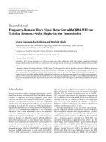
Figure 3: MIMO transmitter model.
for the subsequent IFFT operation. Like MC-CDMA, SC-
CDMA does not preserve the orthogonality among the users
in a frequency-selective channel. It requires advanced mul-
tiuser detection for uplink reception at the base station and
chip equalization for downlink reception at the mobile ter-
minal. On the contrary to MC-CDMA, each user symbol is
spread amongst multiple subchannels of the same power at-
tenuation. The interblock spreading operation is left out by
setting N
inter
= 1.
2.2.2. SCBS-CDMA
The SCBS-CDMA transceiver can be considered as the SC
counterpart of MCBS-CDMA. It is the only SC mode that
entails the interblock spreading operation (N
inter
> 1). The
intrablock spreading matrix θ
m
= F
Q
only performs an FFT
operation to compensate for the subsequent IFFT operation.
If the propagation channels are static, SCBS-CDMA retains
the orthogonality among users in both the up- and downlink,
even after propagation through a frequency-selective chan-
nel (like MCBS-CDMA). It also converts a difficult multiuser
detection problem into an equivalent set of simpler a nd in-
dependent single-user equalization problems. The orthogo-
nality property is however lost in time-selective channels, as
studied numerically in Section 5.
3. EXTENSION TO MULTIPLE ANTENNAS
The generic transmission model is extended in Figure 3 to
include two types of MIMO techniques. We assume N
T
an-
tennas at the transmit side and N
R
antennas at the receive
side. The information symbols d
m
n
T
[i], which are assumed
independent and of variance equal to σ
2
d
, a re first serial-to-
parallel converted into blocks of B symbols, leading to the
block sequence d
m
n
T
[i]:= [d
m
n
T
[iB] ···d
m
n
T
[(i +1)B − 1]]
T
for
n
T
= 1, , N
T
. A MIMO coding operation is performed
across the different transmit antenna streams, that results
into the N
T
antenna sequences s
m
n
T
[ j] input to the generic
transmission scheme. The overall rate increase obtained by
the use of multiple antennas is either 1 or N
T
depending on
the MIMO technique that is selected.
3.1. Space-division multiplexing
In this section, we combine our generic transmission scheme
with SDM, which allows to instantiate all combinations of
SDM with OFDM/SCBT and CDMA as special cases. The
SDM technique is implemented by sending independent
streams on each transmit antenna n
T
, as expressed in
s
m
n
T
[ j] = d
m
n
T
[i], (6)
where j = i.
3.2. Space-time block coding
In this section, we combine our generic transmission scheme
with STBC, which allows to instantiate all combinations of
STBC with OFDM/SCBT and CDMA as special cases. For
conciseness, we limit ourselves to the case of N
T
= 2transmit
antennas (Alamouti scheme [25, 27]). The STBC coding is
implemented by coding the two antenna streams across two
time instants, as expressed in
s
m
1
[j]
s
m
2
[j]
=
d
m
1
[i]
d
m
2
[i]
,
s
m
1
[j +1]
s
m
2
[j +1]
= χ ·
d
m
1
[i]
∗
d
m
2
[i]
∗
,
(7)
where i =j/2 and
χ := χ
N
T
⊗ χ
B
with χ
N
T
:=
0 −1
10
. (8)
In the case of the MC modes, the STBC coding is applied in
the frequency domain on a per-carrier basis s o that
χ
B
:= I
B
. (9)
In the case of the SC modes, the STBC coding is applied in
the time domain by further permuting the vector elements
so that
χ
B
:= F
T
B
· F
B
(10)
is a B × B permutation matrix implementing a time reversal.
It is easily checked that the transmitted block at time in-
stant j + 1 from one antenna is the time-reversed conjugate
of the transmitted s ymbol at time instant j from the other
antenna (with possible permutation and sign change). As we
will show later, this property allows the deterministic trans-
mit stream separation at the receiver, regardless of the under-
lying frequency-selective channels.
4. RECEIVER DESIGN
4.1. Cyclostationarization of the channels
Adopting a discrete-time baseband equivalent model, the
chip-sampled received signal at antenna n
R
(n
R
= 1, , N
R
),
v
n
R
[n], is the superposition of a channel-distorted version of
the MN
T
transmitted user signals, which can be written as
v
n
R
[n] =
M
m=1
N
T
n
T
=1
L
m
l=0
h
m
n
R
,n
T
[l]u
m
n
T
[n − l]+w
n
R
[n], (11)
Flexible Transmission Scheme for 4G Wireless Systems 313
where h
m
n
R
,n
T
[l] is the chip-sampled finite impulse response
(FIR) channel of order L
m
that models the frequency-
selective multipath propagation between the mth user’s an-
tenna n
T
and the base station antenna n
R
, including the ef-
fect of transmit/receive filters and the remaining asynchro-
nism of the quasisynchronous users, and w
n
R
[n] is additive
white Gaussian noise (AWGN) at the base station antenna n
R
with variance σ
2
w
. Further more, the maximum channel or-
der L, that is, L
= max
m
{L
m
}, can be well approximated by
L ≈(τ
max,a
+ τ
max,s
)/T
c
+1,whereτ
max,a
is the maximum
asynchronism between the nearest and the farthest user of
the cell, and τ
max,s
is the maximum excess delay within the
gi ven propagation environment [35].
Assuming perfect time and frequency synchronization,
the sequence v
n
R
[n] is serial-to-parallel converted into the
sequence v
n
R
[n]:= [v
n
R
[nK]···v
n
R
[(n +1)K − 1]]
T
.From
the scalar input/output relationship in (11), we can derive
the corresponding block input/output relationship:
v
n
R
[n] =
M
m=1
N
T
n
T
=1
H
m
n
R
,n
T
[0] · u
m
n
T
[n]
+ H
m
n
R
,n
T
[1] · u
m
n
T
[n − 1]
+ w
n
R
[n],
(12)
where w
n
R
[n]:= [w
n
R
[nK]···w
n
R
[(n +1)K − 1]]
T
is the
corresponding noise block sequence, H
m
n
R
,n
T
[0] is a K × K
lower triangular Toeplitz matrix with entries [H
m
n
R
,n
T
[0]]
p,q
=
h
m
n
R
,n
T
[p − q]forp − q ∈ [0, L
m
]and[H
m
n
R
,n
T
[0]]
p,q
= 0
else, and H
m
n
R
,n
T
[1] is a K × K upper triangular Toeplitz
matrix with entries [H
m
n
R
,n
T
[1]]
p,q
= h
m
n
R
,n
T
[K + p − q]for
K + p − q ∈ [0, L
m
]and[H
m
n
R
,n
T
[1]]
p,q
= 0 else (see, e.g.,
[35] for a detailed derivation of the single-user case). The
delay-dispersive nature of multipath propagation gives rise
to so-called interblock interference (IBI) between successive
blocks, which is modeled by the second term in (12).
The Q × K receive matrix R removes the redundancy
from the chip blocks, that is, y
n
R
[n]:= R · v
n
R
[n]. With
R
= R
cp
= [0
Q×L
, I
Q
], R again discards the length-L cyclic
prefix. The purpose of the transmit/receive pair is twofold.
First, it allows for simple block-by-block processing by re-
moving the IBI, that is, R·H
m
n
R
,n
T
[1]·T = 0
Q×Q
, provided the
CP length to be at least the maximum channel order L. Sec-
ond, it enables low-complexity frequency-domain processing
by making the linear channel convolution to appear circu-
lant to the received block. This results in a simplified block
input/output relationship in the time domain:
y
n
R
[n] =
M
m=1
N
T
n
T
=1
˙
H
m
n
R
,n
T
· x
m
n
T
[n]+z
n
R
[n], (13)
where
˙
H
m
n
R
,n
T
= R · H
m
n
R
,n
T
[0] · T is a circulant channel ma-
trix, and z
n
R
[n] = R · w
n
R
[n] is the corresponding noise
block s equence. Note that circulant mat rices can be diago-
nalized by FFT operations, that is,
˙
H
m
n
R
,n
T
= F
H
Q
· Λ
m
n
R
,n
T
· F
Q
,
where Λ
m
n
R
,n
T
is a diagonal matrix composed of the frequency-
domain channel response between the mth user’s antenna n
T
and the base station antenna n
R
.
4.2. Matrix model
Based on (13), a generalized matrix model is developed that
relates the vector of transmitted user’s symbols to the vector
of received samples. It encompasses all the combinations of
OFDM/SCBT with CDMA considered in this paper as special
cases. Based on this model, a multiuser joint detector opti-
mized according to the MMSE criterion wil l be derived and
its complexity will be reduced by exploiting the cyclostation-
arity properties of the matrices.
The generalized input/output matrix model that relates
the MIMO-coded symbol vector defined as
¯
s[j]:=
¯
s
1
[ j]
T
···
¯
s
M
[ j]
T
T
(14)
with
¯
s
m
[ j]:=
s
m
1
[ j]
T
··· s
m
N
T
[ j]
T
T
(15)
for m = 1, , M to the received and noise vectors defined as
¯
y[j]:=
¯
y
1
[ j]
T
···
¯
y
N
R
[ j]
T
T
,
¯
z[ j]:=
¯
z
1
[ j]
T
···
¯
z
N
R
[ j]
T
T
(16)
with
¯
y
n
R
[ j]:=
y
n
R
jN
inter
T
···
y
n
R
( j +1)N
inter
− 1
T
T
,
¯
z
n
R
[ j]:=
z
n
R
jN
inter
T
···
z
n
R
( j +1)N
inter
− 1
T
T
,
(17)
for n
R
= 1, , N
R
,isgivenby
¯
y[j] = C · F
H
· Λ · θ ·
¯
s[j]+
¯
z[ j], (18)
where the channel matrix is defined as
Λ :=
Λ
1
1
··· 0
Q×Q
.
.
.
.
.
.
.
.
.
0
Q×Q
··· Λ
M
1
.
.
.
.
.
.
.
.
.
Λ
1
N
R
··· 0
Q×Q
.
.
.
.
.
.
.
.
.
0
Q×Q
··· Λ
M
N
R
(19)
with
Λ
m
n
R
:=
Λ
m
n
R
,1
···Λ
m
n
R
,N
T
(20)
314 EURASIP Journal on Wireless Communications and Networking
for m = 1, , M and n
R
= 1, , N
R
, a nd the intrablock
spreading, Fourier, and interblock spreading matrices are de-
fined, respectively, as
θ :=
I
N
T
⊗ θ
1
··· 0
N
T
Q×N
T
B
.
.
.
.
.
.
.
.
.
0
N
T
Q×N
T
B
··· I
N
T
⊗ θ
M
,
F := I
N
R
M
⊗ F
Q
,
C := I
N
R
⊗
C
1
···C
M
,
(21)
in which
C
m
:= c
m
⊗ I
Q
, (22)
with c
m
:= [ c
m
[0] ···c
m
[N
inter
− 1]]
T
. Note that the model
(18) only holds for static channels. In case of time-selective
channels, the channel matrices
˙
H
m
n
R
,n
T
cannot be diagonalized
anymore and are different from one chip block to the next
one.
4.2.1. Space-division multiplexing
Taking (6) into account, the model (18) is instantiated to the
SDM input/output matrix model
¯
y
sdm
[i] = C
sdm
·
F
sdm
H
· Λ
sdm
· θ
sdm
· χ
sdm
·
¯
d[i]
+
¯
z
sdm
[i],
(23)
where the vector of transmitted symbols is defined as
¯
d[i]:=
¯
d
1
[i]
T
···
¯
d
M
[i]
T
T
, (24)
with
¯
d
m
[i]:=
d
m
1
[i]
T
··· d
m
N
T
[i]
T
T
(25)
for m = 1, , M, and the received and noise vectors are de-
fined as
¯
y
sdm
[i]:= y[ j],
¯
z
sdm
[i]:= z[j].
(26)
The MIMO encoding, intrablock spreading, channel,
Fourier, and interblock spreading matrices are, respectively,
given by
χ
sdm
:= I
MN
T
B
,
θ
sdm
:= θ,
Λ
sdm
:= Λ,
F
sdm
:= F,
C
sdm
:= C.
(27)
4.2.2. Space-time block coding
Taking (7) into account, the model (18) is instantiated to the
STBC input/output matrix model
¯
y
stbc
[i] = C
stbc
·
F
stbc
H
· Λ
stbc
· θ
stbc
· χ
stbc
·
¯
d[i]
+
¯
z
stbc
[i],
(28)
where the vector of t ransmitted symbols is given in (25)
assuming that N
T
= 2, the received and noise vectors are
defined as
¯
y
stbc
[i]:=
¯
y[j]
¯
y[j +1]
∗
,
¯
z
stbc
[i]:=
¯
z
[ j]
¯
z[ j +1]
∗
.
(29)
The MIMO encoding, intrablock spreading, channel,
Fourier, and interblock spreading matrices are, respectively,
given by
χ
stbc
:=
I
MN
T
B
I
M
⊗ χ
,
θ
stbc
:=
θ 0
MN
T
Q×MN
T
B
0
MN
T
Q×MN
T
B
θ
∗
,
Λ
stbc
:=
Λ 0
N
R
MQ×MN
T
Q
0
N
R
MQ×MN
T
Q
Λ
∗
,
F
stbc
:=
F 0
N
R
MQ×N
R
MQ
0
N
R
MQ×N
R
MQ
F
∗
,
C
stbc
:=
C 0
N
R
N
inter
Q×N
R
MQ
0
N
R
N
inter
Q×N
R
MQ
C
∗
.
(30)
4.3. Multiuser joint detector
In order to detect the transmitted symbol block of the pth
user
¯
d
p
[i] based on the received sequence of blocks within
the received vector
¯
y
mode
[i] (“mode” stands for “sdm” or
“stbc”), a first solution consists of using a single-user receiver
that inverts successively the channel and all the operations
performed at the transmitter. The single-user receiver relies
implicitly on the fact that CDMA spreading has been applied
on top of a channel equalized in the frequency domain. After
CDMA despreading, each user stream is handled indepen-
dently. However the single-user receiver fails in the uplink
where multiple channels have to be inverted at the same time.
The optimal solution is to jointly detect the transmitted
symbol blocks of the different users within the transmitted
vector
¯
d
[i] based on the received sequence of blocks within
the received vector
¯
y
mode
[i]. The optimum linear joint detec-
tor according to the MMSE criterion is computed in [39]. At
the output of the MMSE multiuser detector, the estimate of
Flexible Transmission Scheme for 4G Wireless Systems 315
the tr ansmitted vector is
ˆ
¯
d[i] =
σ
2
w
σ
2
d
I
MN
T
B
+ G
H
mode
· G
mode
−1
· G
H
mode
·
¯
y
mode
[i],
(31)
where
G
mode
:= C
mode
·
F
mode
H
· Λ
mode
· θ
mode
· χ
mode
. (32)
The MMSE linear joint detector consists of two main opera-
tions [39, 40].
(i) First, a filter matched to the composite impulse re-
sponses multiplies the received vector in order to minimize
the impact of the white noise. The matched filter consists
of the CDMA interblock despreading, the FFT operator to
move to the frequency domain, the maximum ratio combin-
ing (MRC) of the different received antenna channels, the
CDMA intrablock despreading, the IFFT to go back to the
time domain in case of the SC modes, and the STBC decod-
ing.
(ii) Second, the output of the matched filter is still multi-
plied with the inverse of the composite impulse response au-
tocorrelation matrix of size MN
T
B that mitigates the remain-
ing intersymbol, interuser, and interantenna interference.
In the case of interblock spreading (MCBS and SCBS-
CDMA), the spreading matrix C has the property that
C
H
C = I
N
R
QM
if the CDMA codes are chosen orthogo-
nal. When the propagation channels are static, the different
user streams are perfectly separated at the output of the in-
terblock despreading operation and further treated indepen-
dently. The MMSE multiuser joint detector exactly reduces
to independent single-user detectors. In case of time-varying
propagation channels, model (18) is not valid anymore and
the multiuser MMSE joint detector cannot be simplified to
single-user detectors.
In the case of intrablock spreading (MC- and SC-
CDMA), however, the linear MMSE receiver is different from
the single-user receiver, and suffers from a higher computa-
tional complexity. Fortunately, both the initialization com-
plexity, which is required to compute the MMSE receiver, and
the data processing complexity can be significantly reduced
for MC- and SC-CDMA, by exploiting the initial cyclosta-
tionarity property of the channels. Based on a few permuta-
tions a nd on the properties of the block circulant matrices
givenin[12], it can be shown that the initial inversion of the
square autocorrelation matrix of size MN
T
B can be replaced
by the inversion of B square autocorrelation matrices of size
MN
T
.
5. MODE SELECTION STRATEGY
In this section, a cost and performance comparison between
the different communication modes is made, which can serve
as an input for an efficient mode selection strategy.
5.1. Complexity
To evaluate the complexity of the different receivers, we dis-
tinguish between the initialization phase, when the receiver is
calculated, and the data processing phase, when the received
data is actually processed. The rate of the former is related
to the channel’s fading rate, whereas the latter is executed
continuously at the symbol block rate. The complexity will
be described in terms of complex multiply/accumulate cycle
(MAC) operations. It is assumed that 2N
3
complex MAC op-
erations are required to invert a matrix of size N, and that
N log
2
(N) complex MAC operations are required to com-
pute an FFT of size N.
5.1.1. Initialization complexity
The complexity required to compute the MMSE receiver is
given in Tab le 1 for the base station and for the terminal,
respectively. It has been assumed that the inversion of the
MMSE equalizer block diagonal inner matrix is dominant.
Since the size of each block is equal to the number of inter-
fering users times the number of interfering antennas, the
computation of the equalizer is more complex in case of
intrablock spreading (number of interfering users equal to
the number of users) than in case of interblock spreading
(number of interfering users equal to one), and in case of
SDM (number of interfering antennas equal to the number
of tr ansmit antennas) than in case of STBC (number of in-
terfering antennas equal to one).
5.1.2. Data processing complexity
The complexity needed during the data processing phase to
transmit and receive each user’s transmitted complex symbol
is further given in the Ta ble 2. The computational effort is al-
most equally shared between the t ransmitter and the receiver
in the case of the MC-based modes. In the case of the SC-
based modes, all the computational effort has been moved
to the receiver. From a terminal complexity point of view, it
is clearly advantageous to use the SC-based modes in uplink
and the MC-based modes in downlink. Both the transmis-
sion and the reception are less complex in case of interblock
spreading than in case of intrablock spreading, because the
(I) FFT operators can be executed at a lower rate in the for-
mer case (namely, before the spreading at the transmitter and
after the despreading at the receiver). Since STBC combines
N
T
successive symbol blocks, it is on the overall more com-
plex than the SDM scheme.
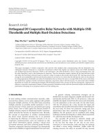
5.2. Peak-to-average power ratio
ThePAPRisillustratedinFigure 4 foreachmodeasafunc-
tion of the spreading factor. The user signals are spread by pe-
riodic Walsh-Hadamard codes for spreading, which are over-
laid with an aperiodic Gold code for scrambling. QPSK mod-
ulation is assumed with Q
= 128 subchannels, and a cyclic
prefix length of L = 32. The PAPR is defined as the maxi-
mum instantaneous peak power over all combinations of the
transmitted symbols divided by the average transmit power.
While the MC-based communication modes feature a
very large PAPR, the SC-based communication modes have
316 EURASIP Journal on Wireless Communications and Networking
Table 1: Initialization complexity, M users, N
T
transmit antennas, Q carriers/subchannels, and B complex symbols per block.
Base station Mobile terminal
SDM STBC SDM STBC
MC/SCBS-CDMA 2QM(N
T
)
3
2MQ 2Q(N
T
)
3
2Q
MC/SC-CDMA 2B(MN
T
)
3
2B(M)
3
2B(MN
T
)
3
2B(M)
3
Table 2: Data processing complexity, M users (M = 1 at the terminal), N
T
transmit antennas, N
R
receive antennas, Q carriers/subchannels,
B complex symbols per block.
Transmitter Receiver
SDM STBC SDM STBC
MCBS-CDMA log
2
QN
T
log
2
Q
N
R
N
T
log
2
Q + N
R
N
R
log
2
Q + N
T
N
R
SCBS-CDMA 00
N
R
N
T
+1
log
2
Q + N
R
N
R
+1
log
2
Q + N
T
N
R
MC-CDMA
Q
MB
log
2
QN
T
Q
MB
log
2
Q
N
R
N
T
Q
MB
log
2
Q + N
R
Q
B
N
R
Q
MB
log
2
Q + N
T
N
R
Q
B
SC-CDMA 00
N
R
N
T
Q
MB
+1
log
2
B + N
R
Q
B
N
R
Q
MB
+1
log
2
B + N
T
N
R
Q
B
76543210
log
2
(spreading factor)
25
20
15
10
5
0
PAPR (dB)
SC-CDMA
SC-BS-CDMA
MC-CDMA
MC-BS-CDMA
Figure 4: PAPR as a function of the spreading factor, QPSK, 128
carriers.
a PAPR close to 0 dB. MC-CDMA has a PAPR improving for
an increasing spreading factor due to the fact that the total
number of possible chip combinations at the output of the
spreading operation is decreasing. The use of the SC-based
communication modes is encouraged in the uplink to re-
duce the power amplifier backoff at the mobile terminal and,
thus, to increase its power efficiency (even if the power am-
plifier backoff is not directly settled based on the low prob-
ability power peak values in the MC-based systems, it is ex-
pected that the variation in instantaneous transmitted power
is much lower in the SC-based systems).
5.3. Goodput performance
We consider a mobile cellular system which op erates in an
outdoor suburban macrocell propagation environment. The
channel model is largely inspired from the 3 GPP TR25.996
geometrical spatial channel model [41]. The radius of the
cell is equal to 3 km. The mobile terminals are moving at a
speed ranging from 0 (static) to 250 km/h (highly mobile).
The system operates at a carrier frequency of 2 GHz, with a
system bandwidth of 5 MHz. Linear antenna arrays are as-
sumed at the mobile terminals and at the base station. An
antenna spacing equal to 0.5 wavelength is selected at the mo-
bile terminals, which results in a correlation equal to 0.2be-
tween the antennas, and an antenna spacing equal to 5 wave-
lengths is selected at the base station, which results in a cor-
relation smaller than 0.1 between the antennas. We assume
a six-sector antenna at the base station and omnidirectional
antennas at the mobile terminals. The propagation environ-
ment is characterized by a specular multipath composed of
6 paths (each path represents the reflection on a scatterer)
and 10 subpaths per path (each subpath represents the re-
flection on a specific part of the scatterer). For each path, the
excess delay standard deviation is equal to 238 nanoseconds,
the angle spread standard deviation at the base station and
that at the mobile terminals are equal to 6 and 68 degrees, re-
spectively. For each subpath, the angle spread standard vari-
ation at the base station and that at the mobile terminals are
equal to 2 and 5 degrees, respectively. The computation of the
path loss is based on the COST231 Hata urban propagation
model.
Monte Carlo simulations have been performed to aver-
age the bit error rate (BER) over 500 stochastic channel re-
alizations, and to compute the corresponding goodput, de-
fined as the throughput offered to the user assuming a re-
transmission of the er roneous packets until they are correctly
Flexible Transmission Scheme for 4G Wireless Systems 317
received. The information bandwidth is spread by the
spreading factor equal to 8. The user signals are spread by pe-
riodic Walsh-Hadamard codes for spreading, which are over-
laid with an aperiodic Gold code for scrambling. QPSK, 16-
QAM, or 64-QAM modulation is used with Q = 128 sub-
channels, and a CP length of L = 32. We assume a packet size
of 512 complex symbols (4 blocks of 128 symbols in case of
MCBS/SCBS-CDMA or 32 blocks of 16 symbols in case of
MC/SC-CDMA). Convolutional channel coding in conjunc-
tion with frequency-domain interleaving is employed ac-
cording to the IEEE 802.11a/g standard. The code rate varies
from 1/2, 2/3, to 3/4. At the receiver, soft-decision Viterbi
decoding is used.
We distinguish between the uplink and the downlink. In
the uplink, transmit power control is applied such that the
received symbol energy is constant for a ll users. The power
transmitted by each terminal depends on the actual channel
experienced by it. The BER (or the goodput) is determined
as a function of the received bit energy, or, equivalently, as
a function of the transmit power averaged over the differ-
ent channel realizations. In the downlink, no transmit power
control is applied. For a constant transmit power at the base
station, the received symbol energy at each terminal depends
on the channel under consideration. The BER (or the good-
put) is determined as a function of the transmit power, or,
equivalently, as a function of the received bit energy averaged
over the channel realizations. For a given received symbol en-
ergy, the required transmit powers for the different commu-
nication modes appear to be very similar.
Rather than comparing all possible modes for the two
link directions, we only consider the relevant modes for each
direction. For the uplink, the SC modes demonstrate two
pronounced advantages compared to MC modes [3]. First,
the SC modes exhibit a smaller PAPR than the MC modes,
which leads to increased terminal power efficiency. Second,
the SC modes allow to move the IFFT at the transmitter to
the receiver, which results in reduced terminal complexity.
For the downlink, the MC modes are the preferred modula-
tion schemes, since they only incur a single FFT operation at
the receiver side which also leads to reduced terminal com-
plexity.
Figure 5 illustrates the user’s goodput in the downlink
of a MCBS-CDMA-based static communication system for
different combinations of the constellation size and channel
coding rate. The signal is received at the terminal through 2
antennas. A typical user’s load of 5 users has been assumed.
Looking to those combinations that give the same asymptotic
goodput (16-QAM and CR 3/4 compared to 64-QAM and
CR 1/2), it is always preferable to combine a high constel-
lation size with a low code rate. The same conclusion holds
in order to select the combination constellation-coding rate
that maximizes the goodput for each SNR value. The enve-
lope is obtained by progressively employing QPSK, 16-QAM,
64-QAM constellations and a code rate equal to 1/2, and then
by increasing the code rate progressively to the values 2/3,
3/4 while keeping the constellation size fixed to 64-QAM.
The gain in communication robustness provided by the use
of more channel coding exceeds the loss in communication
302520151050
E
b
/N
0
(dB)
2
1.5
1
0.5
0
Goodput (Mbps)
QPSK, 1/2
QPSK, 2/3
QPSK, 3/4
16-QAM, 1/2
16-QAM, 2/3
16-QAM, 3/4
64-QAM, 1/2
64-QAM, 2/3
64-QAM, 3/4
Figure 5: Tradeoff between channel coding rate and constellation,
static downlink, MCBS-CDMA, using MRC.
robustness due to the use of a higher constellation. As it will
be shown later, the conclusion may be reversed in a mobile
environment due to better robustness of lower-order map-
pings to changing channel conditions.
Figures 6 and 7 illustrate the gain obtained by the use of
different multiple-antenna techniques in the downlink of an
MCBS-CDMA-based static system and in the uplink of an
SCBS-CDMA-based static system, respectively. Four differ-
ent system configurations are considered (1×1, 1×2, 2×1, 2×
2). A typical user’s load is assumed (number of users equal to
5). Two optimal combinations of the constellation and chan-
nel coding rate are considered (16-QAM with coding rate
1/2, 64-QAM with coding rate 3/4). Exploiting the spatial
diversity at the mobile terminal or at the base station by the
useoftwoantennas(1× 2or2× 1 configurations), MRC
reception, or STBC transmission enables a significant gain in
transmit power (up to 12 dB gain is achieved in the down-
link, up to 7 dB gain is achieved in the uplink). However, the
additional gain obtained by combining STBC transmission
with MRC reception (2 × 2 configuration) is relatively small
(less than 2 dB). SDM suffers from a high 8 dB loss in the
goodput regions that can also be reached by a single-antenna
system (this loss can be reduced if more complex nonlinear
receivers are considered). One can only achieve an increase of
capacity by the use of multiple antennas at very high signal-
to-noise ratio (SNR) values. As a result, we advise to use one
directive antenna at the base station to exploit the very small
angle spread and increase the cell capacity, and two diversity
antennas at the mobile terminal to improve the link reliabil-
ity. The receive MRC technique is performed in the down-
link, while the STBC coding scheme is applied in the up-
link.
318 EURASIP Journal on Wireless Communications and Networking
35302520151050
E
b
/N
0
(dB)
3
2.5
2
1.5
1
0.5
0
Goodput (Mbps)
SISO 1 × 1
MRC 1 × 2
STBC 2 × 1
STBC 2 × 2
SDM 2 × 2
Figure 6: Multiple-antenna gain in the downlink, static environ-
ment, MCBS-CDMA; dashed curves: 16-QAM and coding rate 1/2,
solid curves: 64-QAM and coding rate 3/4.
35302520151050
E
b
/N
0
(dB)
3
2.5
2
1.5
1
0.5
0
Goodput (Mbps)
SISO 1 × 1
MRC 1 × 2
STBC 2 × 1
STBC 2 × 2
SDM 2 × 2
Figure 7: Multiple-antenna gain in the uplink, static environment,
SCBS-CDMA; dashed curves: 16-QAM and coding rate 1/2, solid
curves: 64-QAM and coding rate 3/4.
Figures 8 and 9 illustrate the system performance sensi-
tivity to the user’s load assuming static channels. Interblock
spreading (MCBS-CDMA and SCBS-CDMA) is compared
to intrablock spreading (MC-CDMA and SC-CDMA). The
number of users ranges from 1 to 8. Again the same two com-
binations of the constellation and channel coding rate have
been selected (16-QAM with coding rate 1/2, 64-QAM with
coding rate 3/4). In case of interblock spreading, the MMSE
multiuser receiver reduces to an equivalent but simpler
20151050
E
b
/N
0
(dB)
2
1.8
1.6
1.4
1.2
1
0.8
0.6
0.4
0.2
0
Goodput (Mbps)
IA 1 user
IA 5 users
IA 8 users
IE x users
Figure 8: Impact of the user load on the downlink, static environ-
ment, MCBS-CDMA (IE stands for interblock spreading) and MC-
CDMA (IA stands for intrablock spreading), using MRC; dashed
curves: 16-QAM and coding rate 1/2, solid curves: 64-QAM and
coding rate 3/4.
20151050
E
b
/N
0
(dB)
2
1.8
1.6
1.4
1.2
1
0.8
0.6
0.4
0.2
0
Goodput (Mbps)
IA 1 user
IA 5 users
IA 8 users
IE x users
Figure 9: Impact of the user load on the uplink, static environment,
SCBS-CDMA (IE stands for interblock spreading) and SC-CDMA
(IA s tands for intrablock spreading), using STBC; dashed curves:
16-QAM and coding rate 1/2, solid curves: 64-QAM and coding rate
3/4.
single-user receiver, which performs channel-independent
block despreading followed by MMSE single-user equaliza-
tion. MCBS-CDMA and SCBS-CDMA are MUI-free trans-
mission schemes, such that their user’s goodput remains un-
affected by the user’s load. In case of intrablock spreading,
the MMSE multiuser receiver outperforms the single-user
detector. In the downlink, the performance of the MMSE
multiuser joint detector is slightly decreasing for an in-
creasing number of users and converges to the one of the
Flexible Transmission Scheme for 4G Wireless Systems 319
250200150100500
Speed (km/h)
2
1.8
1.6
1.4
1.2
1
0.8
0.6
0.4
0.2
0
Goodput (Mbps)
16-QAM, 1/2, IA, SNR = 8dB
16-QAM, 1/2, IE, SNR = 8dB
64-QAM, 3/4, IA, SNR = 16 dB
64-QAM, 3/4, IE, SNR = 16 dB
Figure 10: Impact of the terminal speed on the downlink, MCBS-
CDMA (IE stands for interblock spreading) and MC-CDMA (IA
stands for intrablock spreading), using MRC.
single-detector at full user load. MMSE multiuser reception
is especially needed in the uplink, since a single-user receiver
cannot get rid of the MUI, and features a BER curve flat-
tening already at low SNRs. The impact of the user’s load is
much more pronounced in the SC-CDMA uplink than in the
MC-CDMA downlink since the signals propagate through
different channels, which is more difficult to compensate for.
In the downlink, MC-CDMA always outperforms MCBS-
CDMA since it benefits from the frequency diversity offered
by the CDMA spreading. In the uplink, the performance of
SCBS-CDMA is equivalent to the one of SC-CDMA for a typ-
ical user’s load, worse for a small user’s load and better for a
high user’s lo ad.
Figures 10 and 11 compare the effect of the terminal
speed on the user’s goodput in case of intrablock and in-
terblock spreading. A typical user’s load of 5 users has
been assumed, which makes MC-CDMA (SC-CDMA) and
MCBS-CDMA (SCBS-CDMA) perform equally well in static
conditions. For each combination of the constellation and
coding rate, the SNR value corresponding to the maximum
slope in the goodput curves has been chosen (realistic work-
ing point in the curves illustrated in Figures 8 and 9). Since
the symbol block duration is higher in c ase of interblock
spreading than in case of intrablock spreading, the perfor-
mance of MCBS-CDMA (SCBS-CDMA) is significantly re-
duced, while the performance of MC-CDMA (SC-CDMA)
remains acceptable when the speed of the mobile terminals
increases. Since the orthogonality between the users is lost
when the speed increases, the impact is more severe in the
uplink than in the downlink. If a 10-percent performance
loss is acceptable, interblock spreading should be used up to
60 km/h in the downlink or 10 km/h in the uplink for detec-
tion complexity reasons, while intrablock spreading should
250200150100500
Speed (km/h)
2
1.8
1.6
1.4
1.2
1
0.8
0.6
0.4
0.2
0
Goodput (Mbps)
16-QAM, 1/2, IA, SNR = 8dB
16-QAM, 1/2, IE, SNR = 8dB
64-QAM, 3/4, IA, SNR = 16 dB
64-QAM, 3/4, IE, SNR = 16 dB
Figure 11: Impact of the terminal speed on the uplink, SCBS-
CDMA (IE stands for interblock spreading) and SC-CDMA (IA
stands for intrablock spreading), using STBC.
be used for higher speeds. This conclusion is in line with
the two-dimensional spreading strategy proposed in [16, 17]
for a MC-based system, that prioritizes the spreading in the
time domain rather than in the frequency domain, for the
sake of complexity and performance. It is also interesting to
note that the goodput achieved with high constellations at
high speed is smaller than the goodput achieved with low
constellations.
6. CONCLUSIONS
A generic transmission scheme has been designed that al-
lows to instantiate all the combinations of OFDM and
cyclic-prefixed SC modulations w ith DS-CDMA. The SDM
and STBC multiple-antenna techniques have been inte-
grated in the generic transmission scheme. For each resulting
mode, the optimal linear MMSE multiuser receiver has been
derived.
A mode selection strategy has also been proposed that
trades off efficiently the communication performance in a
typical suburban dynamic outdoor environment with the
complexity and PAPR at the mobile terminal.
(i) A hybrid modulation scheme (MC in the downlink,
SC in the uplink) should be used in order to minimize the
mobile terminal PAPR and data processing power.
(ii) Under low-to-medium mobility conditions, it is bet-
ter to use a high constellation and a low channel coding rate
to achieve the maximum goodput for a given SNR value.
However, the lowest constellation order should be selected
under high mobility conditions.
(iii) One directive antenna should be used at the base
station to increase the cell capacity and multiple antennas
should be used at the mobile terminal in combination with
320 EURASIP Journal on Wireless Communications and Networking
diversity techniques like MRC reception and STBC transmis-
sion to improve the link reliability.
(iv) Since interblock and intrablock spreading perform
equally well in typical user loads, interblock spreading should
be used at low terminal speeds to minimize the data pro-
cessing complexity wh ile intrablock spreading should only be
used at high terminal speeds.
It has been demonstrated that an adaptive transceiver is
interesting to support different communication modes and
to efficiently track the changing communication conditions.
REFERENCES
[1] T. Ojanper
¨
a and R. Prasad, Wideband CDMA for Third Gen-
eration Mobile Communications, Artech House, Norwood,
Mass, USA, 1998.
[2] R. van Nee, G. Awater, M. Morikura, H. Takanashi, M. Web-
ster, and K. W. Halford, “New high-rate wireless LAN stan-
dards,” IEEE Commun. Mag., vol. 37, no. 12, pp. 82–88, 1999.
[3] D. Falconer, S. L. Ariyavisitakul, A. Benyamin-Seeyar, and
B. Eidson, “Frequency domain equalization for single-carrier
broadband wireless systems,” IEEE Commun. Mag., vol. 40,
no. 4, pp. 58–66, 2002.
[4] N. Yee, J P. Linnartz, and G. Fettweis, “Multicarrier CDMA
in indoor wireless radio networks,” in Proc. IEEE International
Symposium on Personal, Indoor and Mobile Radio Communi-
cations (PIMRC ’93), vol. 1, pp. 109–113, Yokohama, Japan,
September 1993.
[5] K. Fazel, “Performance of CDMA/OFDM for mobile commu-
nication system,” in Proc. 2nd IEEE Internat ional Conference
on Universal Personal Communications (ICUPC ’93) , vol. 2,
pp. 975–979, Ottawa, Ontario, Canada, October 1993.
[6] K. Fazel, S. Kaiser, and M. Schnell, “A flexible and high
performance cellular mobile communications system based
on multi-carrier SSMA,” Kluwer Journal of Wireless Personal
Communications, vol. 2, no. 1/2, pp. 121–144, 1995.
[7] S. Kaiser, “OFDM code-division multiplexing in fading chan-
nels,” IEEE Trans. Commun., vol. 50, no. 8, pp. 1266–1273,
2002.
[8] V. M. DaSilva and E. S. Sousa, “Multicarrier orthogonal
CDMA signals for quasi-synchronous communication sys-
tems,” IEEE J. Select. Areas Commun., vol. 12, no. 5, pp. 842–
852, 1994.
[9] S. Kondo and L. B. Milstein, “Performance of multicarrier
DS-CDMA systems,” IEEE Trans. Commun.,vol.44,no.2,
pp. 238–246, 1996.
[10] L L. Yang and L. Hanzo, “Multicarrier DS-CDMA: a multiple
access scheme for ubiquitous broadband wireless communi-
cations,” IEEE Commun. Mag., vol. 41, no. 10, pp. 116–124,
2003.
[11] F. Petr
´
e, G. Leus, M. Moonen, and H. De Man, “Multi-
carrier block-spread CDMA for broadband cellular down-
link,” EURASIP Journal on Applied Signal Processing, vol. 2004,
no. 10, pp. 1568–1584, 2004, Special Issue on Multi-Carrier
Communications and Signal Processing .
[12] M. Vollmer, M. Haardt, and J. Gotze, “Comparative study of
joint-detection techniques for TD-CDMA based mobile ra-
dio systems,” IEEE J. Select. Areas Commun.,vol.19,no.8,
pp. 1461–1475, 2001.
[13] K. L. Baum, T. A. Thomas, F. W. Vook, and V. Nangia,
“Cyclic-prefix CDMA: an improved transmission method for
broadband DS-CDMA cellular systems,” in Proc. IEEE Wire-
less Communications and Networking Conference (WCNC ’02),
vol. 1, pp. 183–188, Orlando, Fla, USA, March 2002.
[14] S. Zhou, G. B. Giannakis, and C. Le Martret, “Chip-
interleaved block-spread code division multiple access,” IEEE
Trans. Commun., vol. 50, no. 2, pp. 235–248, 2002.
[15] F. Petr
´
e,G.Leus,L.Deneire,andM.Moonen,“Downlink
frequency-domain chip equalization for single-carrier block
transmission DS-CDMA with known symbol padding,” in
Proc. IEEE Global Telecommunications Conference (GLOBE-
COM ’02), vol. 1, pp. 453–457, Taipei, Taiwan, November
2002.
[16] H. Atarashi, N. Maeda, S. Abeta, and M. S awahashi, “Broad-
band packet wireless access based on VSF-OFCDM and
MC/DS-CDMA,” in Proc. 13th IEEE International Sympo-
sium on Personal, Indoor and Mobile Radio Communications
(PIMRC ’02), vol. 3, pp. 992–997, Lisbon, Portugal, Septem-
ber 2002.
[17] N. Chapalain, D. Mottier, and D. Castelain, “An OFCDM up-
link transmission system with channel estimation based on
spread pilots,” in Proc. IST Mobile and Wireless Communica-
tions Summit, Lyon, France, June 2004.
[18] G. J. Foschini and M. J. Gans, “On limits of wireless commu-
nications in a fading environment when using multiple an-
tennas,” Kluwer Journal of Wireless Personal Communications,
vol. 6, no. 3, pp. 311–335, 1998.
[19] G. G. Raleigh and J. M. Cioffi, “Spatio-temporal coding
for wireless communication,” IEEE Trans. Commun., vol. 46,
no. 3, pp. 357–366, 1998.
[20] D.Gesbert,H.Bolcskei,D.A.Gore,andA.J.Paulraj,“Out-
door MIMO wireless channels: models and performance pre-
diction,” IEEE Trans. Commun., vol. 50, no. 12, pp. 1926–
1934, 2002.
[21] A. J. Paulraj and T. Kailath, “Increasing capacit y in wireless
broadcast systems using distributed transmission/directional
reception (DTDR),” U.S. Patent 5345599, Stanford University,
Stanford, Calif, USA, 1994.
[22] G. J. Foschini, “Layered space-time architecture for wireless
communication in a fading environment when using multiple
antennas,” B ell Labs Technical Journal, vol. 1, no. 2, pp. 41–59,
1996.
[23] F.W.Vook,T.A.Thomas,andK.L.Baum,“Transmitarray
processing for cyclic-prefix CDMA,” in Proc. 56th IEEE Ve-
hicular Technology Conference (VTC ’02), vol. 1, pp. 270–274,
Vancouver, British Columbia, Canada, September 2002.
[24] V. Tarokh, N. Seshadri, and A. R. Calderbank, “Space-time
codes for high data rate wireless communication: perfor-
mance criterion and code construction,” IEEE Trans. Inform.
Theory, vol. 44, no. 2, pp. 744–765, 1998.
[25] S. M. Alamouti, “A simple transmit diversity technique for
wireless communications,” IEEE J. Select. Areas Commun.,
vol. 16, no. 8, pp. 1451–1458, 1998.
[26] V. Tarokh, H. Jafarkhani, and A. R. Calderbank, “Space-time
block codes from orthogonal designs,” IEEE Trans. Inform.
Theory, vol. 45, no. 5, pp. 1456–1467, 1999.
[27] E. Lindskog and A. J. Paulraj, “A transmit diversity scheme for
channels with intersymbol interference,” in Proc. IEEE Inter-
national Conference on Communications (ICC ’00), vol. 1, pp.
307–311, New Orleans, La, USA, June 2000.
[28] N. Al-Dhahir, “Single-carrier frequency-domain equalization
for space-time block-coded transmissions over frequency-
selective fading channels,” IEEE Commun. Lett.,vol.5,no.7,
pp. 304–306, 2001.
[29] S. Zhou and G. B. Giannakis, “Single-carrier space-time
block-coded transmissions over frequency-selective fading
channels,” IEEE Trans. Inform. Theory, vol. 49, no. 1, pp. 164–
179, 2003.
[30] S. Barbarossa and F. Cerquetti, “Simple space-time coded
Flexible Transmission Scheme for 4G Wireless Systems 321
SS-CDMA systems capable of perfect MUI/ISI elimination,”
IEEE Commun. Lett., vol. 5, no. 12, pp. 471–473, 2001.
[31]F.W.Vook,T.A.Thomas,andK.L.Baum,“Cyclic-prefix
CDMA with antenna diversity,” in Proc. 55th IEEE Vehicu-
lar Technology Conference (VTC ’02), vol. 2, pp. 1002–1006,
Birmingham, Ala, USA, May 2002.
[32] F. Petr
´
e,G.Leus,L.Deneire,M.Engels,M.Moonen,and
H. De Man, “Space-time block coding for single-carrier
block transmission DS-CDMA downlink,” IEEE J. Select. Ar-
eas Commun., vol. 21, no. 3, pp. 350–361, 2003, Special Issue
on MIMO Systems and Applications .
[33] Z. Liu and G. B. Giannakis, “Space-time block-coded multi-
ple access through frequency-selective fading channels,” IEEE
Trans. Commun., vol. 49, no. 6, pp. 1033–1044, 2001.
[34] A. Stamoulis, Z. liu, and G. B. Giannakis, “Space-time block-
coded OFDMA with linear precoding for multirate services,”
IEEE Trans. Signal Processing, vol. 50, no. 1, pp. 119–129, 2002.
[35] Z. Wang and G. B. Giannakis, “Wireless multicarrier commu-
nications,” IEEE Signal Processing Mag.,vol.17,no.3,pp.29–
48, 2000.
[36] G. B. Giannakis, P. A. Anghel, and Z. Wang, “Wideband gen-
eralized multicarrier CDMA over frequency-selective wire-
less channels,” in Proc. IEEE Int. Conf. Acoustics, Speech, Sig-
nal Processing (ICASSP ’00), vol. 5, pp. 2501–2504, Istanbul,
Turkey, June 2000.
[37] G. B. Giannakis, Z. Wang, A. Scaglione, and S. Bar-
barossa, “AMOUR-generalized multicarrier transceivers for
blind CDMA regardless of multipath,” IEEE Trans. Commun.,
vol. 48, no. 12, pp. 2064–2076, 2000.
[38] Q. Chen, E. S. Sousa, and S. Pasupathy, “Performance of a
coded multi-carrier DS-CDMA system in multipath fading
channels,” Kluwer Journal of Wireless Personal Communica-
tions, vol. 2, no. 1-2, pp. 167–183, 1995.
[39] A. Klein, G. K. Kaleh, and P. W. Baier, “Zero forcing and mini-
mum mean-square-error equalization for multiuser detection
in code-division multiple-access channels,” IEEE Trans. Veh.
Technol., vol. 45, no. 2, pp. 276–287, 1996.
[40] L. Vandendorpe, “Performance analysis of IIR and FIR lin-
ear and decision-feedback MIMO equalizers for transmulti-
plexers,” in Proc. IEEE International Conference on Commu-
nications (ICC ’97), vol. 2, pp. 657–661, Montreal, Quebec,
Canada, June 1997.
[41] 3GPP Technical specification group, “TR25.996 v6.1.0, Spatial
channel model for Multiple Input Multiple Output (MIMO)
simulations,” September 2003.
Franc¸ois Horlin wasborninBruxelles,Bel-
gium, in 1975. He received the Electri-
cal Engineering degree and the Ph.D. de-
gree from the Universit
´
e catholique de Lou-
vain (UCL), Louvain-la-Neuve, Belgium, in
1998 and 2002, respectively. In September
2002, he joined the Interuniversity Micro-
Electronics Center (IMEC), Leuven, Bel-
gium, as a Senior Researcher. He is currently
the Head of the research activities on dig ital
signal processing for broadband communications. His fields of in-
terest are in digital signal processing, mainly for high-bit-rate mul-
tiuser communications. During his Ph.D. thesis, he proposed a new
solution for jointly optimizing the transmitter and the receiver in a
multiuser multi-input multi-output (MIMO) type of communica-
tion systems. He is now working on the integration of a multistan-
dard mobile terminal. In this context, he is responsible for the de-
velopment of the functionality of a fourth-generation (4G) cellular
system, targeting high capacity in very high mobility conditions.
Frederik Petr
´
e was born in Tienen, Bel-
gium, on December 12, 1974. He received
the Electrical Engineering degree and the
Ph.D. degree in applied sciences from the
Katholieke Universiteit Leuven (KULeu-
ven), Leuven, Belgium, in July 1997 and
December 2003, respectively. In September
1997, he joined the Design Technology for
Integrated Information and Communica-
tion Systems (DESICS) Division at the In-
teruniversity Micro-Electronics Center (IMEC) in Leuven, Bel-
gium. Within the Digital Broadband Terminals (DBATE) Group
of DESICS, he first performed predoctoral research on wireline
transceiver design for twisted pair, coaxial cable, and powerline
communications. During the fall of 1998, he visited the Informa-
tion Systems Laboratory (ISL) at Stanford University, Calif, USA,
working on OFDM-based powerline communications. In January
1999, he joined the Wireless Systems (WISE) Group of DESICS
as a Ph.D. researcher, funded by the Institute for Scientific and
Technological Research in Flanders (IWT). Since January 2004, he
has been a Senior Scientist within the Wireless Research Group of
DESICS. He is investigating the baseband signal processing algo-
rithms and architectures for future wireless communication sys-
tems, like third-generation (3G) and fourth-generation (4G) cel-
lular networks, and wireless local area networks (WLANs). His
main research interests are in modulation theory, multiple-access
schemes, channel estimation and equalization, smart antenna, and
MIMO techniques. He is a Member of the ProRISC Technical Pro-
gram Committee and the IEEE Benelux Section on Communica-
tions and Vehicular Technology (CVT). He is a Member of the Ex-
ecutive Board and Project Leader of the Flexible Radio Project of
the Network of Excellence in Wireless Communications (NEW-
COM), established under the sixth framework of the European
Commission.
Eduardo Lopez-Est raviz was born in Fer-
rol, Spain, in 1977. He received the
Telecommunications Engineering degree
from the Universidad de Vigo (UVI), Vigo,
Spain, in 1996 and 2002, respectively. In
June 2002, he joined the Interuniversity
Micro-Electronics Center (IMEC), Leuven,
Belgium, as a researcher. His fields of inter-
est are in dig ital signal processing for broad-
band communications. He is now working
on the integration of a multistandard mobile terminal. In this
context, he is working on developing functionality for a fourth-
generation (4G) cellular system, targeting high capacity in very
high mobility conditions.
Frederik Naessens wasborninRoeselare,
Belgium, in 1979. He received the Engi-
neering degree from the Catholic School for
Higher Education Bruges-Ostend (KHBO)
Academy in Ostend, Belgium, in 2001. Af-
ter this studies, he joined the Interuniversity
Micro-Electronics Center (IMEC), Leuven,
Belgium, as a development engineer. Cur-
rently he is also a part-time student follow-
ing an M.S. degree in ICT at the University
of Kent, United Kingdom. He has been involved in a demonstra-
tor setup for GPS and GLONASS satellite navigation systems. He
is now working on developing functionality for future cellular sys-
tems (4G ).
322 EURASIP Journal on Wireless Communications and Networking
Liesbet Van der Perre received the M.S. de-
gree and the Ph.D. degree in electrical engi-
neering from the KU Leuven, Belgium, in
1992 and 1997, respectively. Her work in
the past focused on system design and dig-
ital modems for high-speed wireless com-
munications. She was a System Architect in
IMEC’s OFDM ASICs development and a
Project Leader for the turbo codec. Cur-
rently, she is leading the Software-Defined
Radio Baseband Project, and she is the Scientific Director of Wire-
less Research in IMEC.