Báo cáo hóa học: " Extended Lock Range Zero-Crossing Digital Phase-Locked Loop with Time Delay" pot
Bạn đang xem bản rút gọn của tài liệu. Xem và tải ngay bản đầy đủ của tài liệu tại đây (836.96 KB, 6 trang )
EURASIP Journal on Wireless Communications and Networking 2005:3, 413–418
c
2005 Qassim Nasir
Ex tended Lock Range Zero-Crossing Digital
Phase-Locked Loop with Time Delay
Qassim Nasir
Department of Electrical and Computer Engineering, College of Engineering, University of Sharjah, P.O. Box 27272, Sharjah, UAE
Email:
Received 7 November 2004; Revised 21 May 2005; Recommended for Publication by Jonathon Chambers
The input frequency limit of the conventional zero-crossing digital phase-locked loop (ZCDPLL) is due to the operating time of
the digital circuitry inside the feedback loop. A solution that has been previously suggested is the introduction of a time delay in
the feedback path of the loop to allow the digital circuits to complete their sample processing before the next sample is received.
However, this added delay will limit the stable operation range and hence lock range of the loop. The objective of this work is to
extend the lock range of ZCDPLL w i th time delay by using a chaos control. The tendency of the loop to diverge is measured and
fed back as a form of linear stabilization. The lock range extension has been confirmed through the use of a bifurcation diagram,
and Lyapunov exponent.
Keywords and phrases: nonuniform sampling, digital phase locked loops, chaos control.
1. INTRODUCTION
Digital phase locked loops (DPLLs) were introduced to min-
imize some of the problems associated with the analogue
loops such as sensitivity to DC drift and the need for peri-
odic adjustments [1, 2].ThemostcommonlyusedDPLLis
the zero-crossing digital phase-locked loop (ZCDPLL). The
ZCDPLL operation is based on nonuniform sampling tech-
niques. The loop is simple to implement and easy to model.
The ZCDPLL consists of a sampler that acts as phase detector,
digital filter, and digital-controlled oscillator (DCO). In the
ZCDPLL, there is a limit on the frequency of the incoming
signal beyond which the loop ceases to function properly any
longer. This limit is reached when the period of the incoming
signal becomes equal to the total operating time of the digi-
tal circuits in the loop. O ne way to increase this upper limit
of the input frequency is by the introduction of a time delay
in the loop. In this case the sampling instances controlled by
the DCO are determined by the sample of the input which
was taken two sampling intervals earlier. Therefore, the up-
per limit of the operating frequency of the ZCDPLL can be
increased. The introduction of the delay, however, will limit
the loop stability range or the lock range of the loop as w ill
be seen later.
The objective of this work is to increase the stability
and lock range of ZCDPLL with time delay by incorporat-
This is an open access article distributed under the Creative Commons
Attribution License, which permits unrestricted use, distribution, and
reproduction in any medium, provided the original work is properly cited.
ing a chaos control technique known as “time-delayed feed-
back stabilization.” The ZCDPLL has been shown to exhibit
chaotic behaviour in the unstable region of operation [3].
Time-delayed feedback stabilization introduced by Pyragas
consists of a continuous linear feedback applied at each com-
putation time step which stabilizes unstable periodic orbits
(UPO) [4]. Pyragas’s method is used to broaden the track-
ing range by extending the stable operation behaviour of
the first-order ZCDPLL to a larger control parameter (K
1
),
which leads to larger input frequency w. Our results are based
on bifurcation theory a nd numerical simulation. Chaos con-
trol technique is used to overcome the problem of limited
operating range when a time delay is added to the feedback
path of the loop. The paper analyzes the steady-state loop op-
eration ZCDPLL and chaos-controlled ZCDPLL. The pull-
in behaviour, higher-order loops will be considered in future
work.
In Section 2 , the ZCDPLL with time delay model is de-
scribed Section 3 presents the chaos control technique used
to broaden the lock range. In Section 4 simulation results are
presented, and finally conclusions are given in Section 5.
2. ZCDPLL WITH TIME DELAY
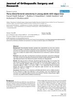
The structure of ZCDPLL with time delay is shown in
Figure 1. The first register simply serves to store incoming
data temporarily until the filter portion finishes its operation
on previous data. As soon as the filter finishes its operation,
the stored data are tra nsferred to the second register and the
first register is cleared to be ready for taking in new data.
414 EURASIP Journal on Wireless Communications and Networking
G
1
D(z)
+
y
k−1
y
k−2
Delay
DCO
t
k
Register
II
b
+−
Chaos
control
Delay
x
k−1
Register
I
x
k
n(t)
+
x(t)
s(t)
Figure 1: Block diag ram of chaos-controlled ZCDPLL with time delay.
The input signal to the loop is taken as x(t) = s(t)+n(t),
where s(t) = A sin(w
0
t + θ(t)), n(t) is additive white Gaus-
sian noise ( AWGN); θ(t) = θ
0
+ Ω
0
t from which the signal
dynamics are modeled; θ
0
is the initial phase which we will
assume to be zero; Ω
0
is the frequency offset from the nomi-
nal value w
0
. The input signal is sampled at time instances t
k
determined by the digital-controlled oscillator (DCO). The
DCO period control algorithm as given by [5]is
T
k
= T
0
− y
k−2
= t
k
− t
k−1
,(1)
where T
0
= (2π/w
0
) is the nominal period, y
k−2
is the de-
layed output of the loop digital filter D(z).Thesamplevalue
of the incoming signal x(t)att
k
is
x
t
k
= s
t
k
+ n
t
k
(2)
or
x
k
= s
k
+ n
k
,(3)
where s
k
= A sin[w
0
t
k
+ θ(t
k
)]. The sequence x
k
is passed
through a digital filter D(z) whose output y
k
is used to con-
trol the period of the DCO. The time instances t
k
can be
rewritten as
t
k
=
k
i=1
T
i
= kT
0
−
k−2
i=0
y
i
, k = 1, 2, 3, (4)
Thus
x
k
= A sin
w
0
kT
0
−
k−2
i=0
y
i
+ θ
k
+ n
k
. (5)
For noise-free analysis n
k
= 0, then
x
k
= A sin
w
0
kT
0
−
k−2
i=0
y
i
+ θ
k
. (6)
The phase error is defined to be
φ
k
= θ
k
− w
0
k−2
i=0
y
i
. (7)
Also
φ
k−1
= θ
k−1
− w
0
k−3
i=0
y
i
. (8)
Taking the difference of (7)and(8) results in
φ
k
− φ
k−1
= θ
k
− θ
k−1
− w
0
y
k−2
. (9)
The z transform of the output of the digital filter is
Y(z) = D(z)X(z), (10)
where X(z) is the z transform of x(t). If the digital filter used
is a g ain block only, then D(z) = G
1
,whereG
1
is the block
gain. In this case Y(z) = G
1
X(z), and the time domain equiv-
alent will be y
k
= G
1
x
k
= AG
1
sin[φ
k
].
IfafrequencystepΩ
0
= (w − w
0
) is applied, then θ
k
=
(w − w
0
)t
k
. Using (4), then
θ
k
− θ
k−1
=
w − w
0
T
0
−
w − w
0
y
k−2
. (11)
Equation (9) can also be rewritten as
φ
k
= φ
k−1
− K
1
sin
φ
k−2
+ Λ
0
= f (φ), (12)
where Λ
0
= (w − w
0
)T
0
= 2π((w − w
0
)/w
0
), K
1
= wG
1
A.It
can be easily shown that this system has equilibrium state at
sin
−1
(Λ
0
/K
1
), not at φ = 0. This implies that |Λ
0
/K
1
| < 1, or
K
1
> |Λ
0
|. The following transformation makes the equilib-
rium at φ = 0:
ψ
k
= φ
k
− sin
−1
Λ
0
K
1
, (13)
Extended Lock Range ZCDPLL with Time Delay 415
then
ψ
k
= ψ
k−1
− K
2
sin
ψ
k−2
− Λ
0
cos
ψ
k−2
+ Λ
0
, (14)
where K
2
=
K
2
1
− Λ
2
0
. Define the system state vector ζ
k
=
ψ
k−2
, ξ
k
= ψ
k−1
, x = (ζ, ξ)
T
, then (14)canberewrittenas
ζ
k+1
ξ
k+1
=
ξ
k
ξ
k
− K
2
sin
ζ
k
− Λ
0
cos
ζ
k
+ Λ
0
g
1
x
k
g
2
x
k
.
(15)
If the system equation is linearised around the equilibrium
x = 0, so that sin(ζ
k
) ≈ ζ
k
,sin(ξ
k
) ≈ ξ
k
,cos(ζ
k
) ≈ 1,
cos(ξ
k
) ≈ 1, then (15)becomes
ζ
k+1
ξ
k+1
=
ζ
k
ξ
k
− K
2
ζ
k
=
01
−K
2
1
ζ
k
ξ
k
= Bx
k
. (16)
To satisfy Lyapunov stability criterion for the above system,
the matrix B
T
B − I must be negative definite. This implies
that the eigenvalues of B
T
B must be less than one [6]. This
in turn results that K
2
2
< 1orK
1
<
1+Λ
2
0
, which is less
than that of conventional ZCDPLL range of operation (K
1
<
4+Λ
2
0
)[5].
We re-examine the loop stability in terms of the variable
K
10
= (G
1
w
0
A), which is directly related to the filter gain and
free running frequency of the DCO. In this case,
2π
w
w
0
− 1
<K
10
w
w
0
<
1+(2π)
2
w
w
0
− 1
2
. (17)
The condition of the convergence becomes
2π
1 −
w
0
w
<K
10
<
1+(2π)
2
w
0
w
2
−2(2π)
2
w
0
w
+(2π)
2
.
(18)
3. EXTENDED LOCK RANGE ZCDPLL
WITH TIME DELAY
The time-delayed feedback stabilization introduced by Pyr a-
gas is incorporated and used to extend the stable behaviour of
ZCDPLL with time delay to larger values of K
1
.Justbeyond
the critical values of K
1
, the tendency of the loop to converge
to UPO is measured by the value ∆x
k−1
= A(sin(φ
k−1
) −
sin(φ
k−2
)). A multiple of these differences b∆x
k
1
,whereb is
an empirical adjustable weight, is fed back as a form of non-
linear stabilization [7]. The resultant system dynamics will
be
φ
k
= φ
k−1
−
K
1
+ b
sin
φ
k−2
+ b sin
φ
k−1
+ Λ
0
. (19)
I
II
III b =−0.4
III b =−0.6
0.20.40.60.811.21.41.61.82
w
0
/w
0
0.5
1
1.5
2
2.5
3
3.5
4
4.5
Gain K
10
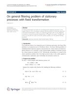
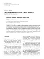
Figure 2: Frequency lock region as a function of K
10
and w
0
/w.
Using the same procedure of previous section, (17)canbe
written as
ζ
k+1
ξ
k+1
=
ξ
k
ξ
k
1+b
K
2
K
1
− K
2
1+b
K
2
K
1
ζ
k
g
1
x
k
g
2
x
k
=
01
−K
2
rr
ζ
k
ξ
k
,
(20)
where r = 1+b(K
2
/K
1
). Following the Lyapunov stability
criteria, K
2
2
should be less than 1/r
2
in order to guar antee
that the eigenvalues of B
T
B are less than one. The condition
for the loop locking is
K
2
1
− Λ
2
0
1+b
K
2
1
− Λ
2
0
K
1
2
< 1. (21)
Stabilization corresponds to negative values of (b), in
which the feedback term corrects the tendency to UPO [7].
Since b is negative, then r will be less than one and this will
ensure that the loop can have K
1
higher than that for ZCD-
PLL with time delay derived in previous section. T he conver-
gence region of the conventional ZCDPLL with time delay
described by (18) and the proposed chaos-controlled ZCD-
PLL described by (21)fordifferent input frequency offsets
have been plotted in Figure 2. The region between the curves
I and II indicates the region of stable operation for the con-
ventional ZCDPLL, while the reg ion between the curves I
and III represents that for the proposed loop plotted for dif-
ferent values of b. It is clear that the widest lock range occurs
at K
10
= 1.0fortheconventionalZCDPLL,whileitwillbeat
K
10
= 1.5 when the value of b is −0.4 for the proposed chaos-
controlled ZCDPLL. Figure 2 also shows that when the value
of b is increased to −0.6, the proposed chaos-controlled loop
has widest lock range occurring at K
10
≈ 2.0. So the greater
the absolute value of b, the wider the lock range. Thus, the
K
10
, w
0
/w plane gives a realistic indication of the loop’s abil-
ity to track frequency offsets.
416 EURASIP Journal on Wireless Communications and Networking
00.511.522.533.5
K
1
−4
−3
−2
−1
0
1
Max LE
00.511.522.533.5
K
1
−4
−2
0
2
4
φ
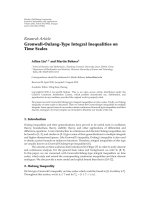
Figure 3: Bifurcation of conventional ZCDPLL with Λ
0
= 0.4.
00.511.522.533.5
K
1
−0.8
−0.6
−0.4
−0.2
0
0.2
0.4
0.6
Max LE
00.511.522.533.5
K
1
−4
−2
0
2
4
φ
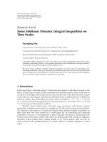
Figure 4: Bifurcation of ZCDPLL with delay with Λ
0
= 0.4.
The nonlinear feedback procedure is applied without a
priori knowledge of the location of the periodic orbits. A
disadvantage of the method is that it achieves control over
a limited range of the parameter space (b values). A given or-
bit will become eventually unstable if the feedback parameter
is var ied beyond that range.
4. SYSTEM PERFORMANCE
Consider a modulation-free input signal y(t)
= sin(wt),
where the center frequency of the DCO is w
0
= 1. After
discarding the first 1000 points, the next 100 000 points are
collected and recorded to produce a bifurcation plot and
maximum Lyapunov exponent. The numeric bifurcation di-
agrams will be used to study the operation range of the ZCD-
PLL with time delay. Along the horizontal axis of the bifur-
cation diagram, the parameter K
1
of the system is varied,
while the successive values of the phase error φ
k
are plotted.
00.511.522.5
K
1
−1.2
−1
−0.8
−0.6
−0.4
−0.2
0
0.2
Max LE
00.511.522.5
K
1
−4
−2
0
2
4
φ
Figure 5: Bifurcation of chaos-controlled ZCDPLL with delay with
Λ
0
= 0.4andb =−0.7.
Lyapunov exponent can be used to measure the exponential
divergence of trajectory in a dynamical system. The exponent
measures the average rate of separation of two nearby tra-
jectories coming from different initial conditions. A positive
Lyapunov exponent indicates chaos and the system will be
very sensitive to initial conditions. The largest Lyapunov ex-
ponent (LE) for the two-dimensional dynamical systems is
defined as [8]
LE = lim
N→∞
1
2N
N−1
n=0
ln
a + bY
n
2
+
c + dY
n
2
1+Y
2
n
, (22)
where Y
is the tangent of the direction of maximum growth
which evolves according to
Y
n+1
=
c + dY
n
a + bY
n
, (23)
and a = ∂g
1
/∂x
k
, b = ∂g
1
/∂y
k
, c = ∂g
2
/∂x
k
,andd = ∂g
2
/∂y
k
are members of the Jacobian matrix of (15), (16), and (20).
In order to study the behaviour of the ZCDPLL with
time delay, it is advantageous to use bifurcation diagrams and
maximum LE. Figure 3 shows the bifurcation diagrams and
maximum Lyapunov exponent of conventional first-order
loop ZCDPLL as the controlled parameter K
1
is varied from
0upto3.5. It shows that the loop has stable operation for
Λ
0
<K
1
<
4+Λ
2
0
and this agrees with the normal loop
operation found earlier [5]. Also it shows that LE will be
positive in the chaotic operation range. When a time delay
is added to conventional ZCDPLL, the range of K
1
which of-
fers stable loop operation is reduced as shown in Figure 4 and
the new value is only Λ
0
<K
1
<
1+Λ
2
0
. This agrees with
the range derived in Section 2. This reduced operation range
will affect the lock range of the loop. The bifurcation plot
and LE for ZCDPLL with time delay is provided in Figure 5
Extended Lock Range ZCDPLL with Time Delay 417
b =−0.1
b =−0.2
b =−0.4
11.11.21.31.41.51.61.71.81.92
K
1
−0.4
−0.3
−0.2
−0.1
0
0.1
0.2
0.3
Max LE
Figure 6: Maximum Lyapunov of chaos-controlled ZCDPLL with
delay for different values of b when Λ
0
= 0.4.
for the control parameter b =−0.7, where b = 0corre-
sponds to the conventional ZCDPLL. It is clear that chaos-
controlled ZCDPLL will start period doubling process when
K
1
= 1.7comparedtoK
1
= 1.1 for conventional ZCD-
PLL with time delay. The proposed chaos-controlled ZCD-
PLL with time delay extends the stable region of operation
to higher values of K
1
which leads to higher operating fre-
quency (higher tracking range). Figure 6 shows the variation
of largest Lyapunov exponent versus the value of K
1
for dif-
ferent values of the feedback control parameter (b). A pos-
itive largest Lyapunov exponent corresponds to chaotic op-
eration. It can be seen that chaos-controlled ZCDPLL of-
fers convergent-to-fixed point operation at higher K
1
values
compared to conventional ZCDPLL. Figure 6 indicates that
for b =−0.4 , the highest value of K
1
will be around 1.65 and
this corresponds to 1.5 times the highest input frequency of
conventional loop. If the absolute value of b is increased fur-
ther to about b =−2.0, the loop can no longer be controlled
and it will exhibit chaotic behaviour as shown in Figure 7.So
it is desirable to select the value of b carefully to avoid such
chaotic loop operation.
5. CONCLUSIONS
The limit on the incoming signal frequency beyond which
the zero-crossing digital phase-locked loop (ZCDPLL) does
not func tion properly can be extended by the addition of
a time delay in the feedback path of the loop. This paper
has proposed and described a chaos control technique to
broaden the tracking range of ZCDPLL with time delay. The
delayed feedback control method of chaos control proposed
by Pyr a gas is used to stabilize the ZCDPLL chaotic opera-
tion.Afeedbackloopwhichmeasureslooptendencytochaos
is used to bring the ZCDPLL from chaotic operation region
back to its stable orbit. The bifurcation plot and largest Lya-
b =−1
b =−2
11.21.41.61.822.22.42.62.83
K
1
−1.2
−1
−0.8
−0.6
−0.4
−0.2
0
0.2
0.4
Max LE
Figure 7: Maximum Lyapunov of chaos-controlled ZCDPLL with
delay for different values of b when Λ
0
= 0.4.
punov exponent shown in Figures 5 and 6 display the de-
pendence of chaos-controlled ZCDPLL convergent opera-
tion upon the feedback parameter b. As the feedback con-
trol parameter b is varied, the loop will remain in stable orbit
forlargervaluesofK
1
. This will extend the range of incom-
ing signal frequency or expand the t racking range. While the
conventional ZCDPLL bifurcated when K
1
≈ 1.1, Figure 5
shows that the chaos-controlled ZCDPLL bifurcates when
K
1
≈ 1.7. The same effect can be seen when maximum Lya-
punov exponent is determined instead of the bifurcation di-
agram as shown in Figure 6. The Lyapunov exponent will be
positive at higher value of K
1
as the absolute value of the
control parameter b is increased and hence wider lock range.
Figure 7 indicates that if the absolute value of b is increased
such that b =−2, the chaos-controlled ZCDPLL with time
delay is completely unstable for the range of K
1
used. So it is
desirable to select the value of b carefully to avoid such un-
controlled chaotic behaviour of the loop.
REFERENCES
[1] W. Lindsay and C. M. Chie, “A survey of digital phase locked
loops,” Proc. IEEE, vol. 69, no. 4, pp. 410–431, 1981.
[2] G C. Hsieh and J. C. Hung, “Phase-locked loop techniques. A
survey,” IEEE Trans. Ind. Electron., vol. 43, no. 6, pp. 609–615,
1996.
[3] Q. Nasir, “Chaotic behaviour of first order zero crossing digi-
tal phase locked loop,” in Proc. IEEE Asia-Pacific Conference on
Circuits and Systems (APCCAS ’04), vol. 2, pp. 977–980, Tainan,
Taiwan, December 2004.
[4] K. Pyragas, “Continuous control of chaos, by self-controlling
feedback,” Physics Letters A, vol. 170, no. 6, pp. 421–428, 1992.
[5] H. C. Osborne, “Stability analysis of an Nth power digital
phase-locked loop-part I: first-order DPLL,” IEEE Trans. Com-
mun., vol. 28, no. 8, pp. 1343–1354, 1980.
[6] J. Slotine and W. Li, Applied Nonlinear Control, Prentice-Hall,
Englewood Cliffs, NJ, USA, 1991.
418 EURASIP Journal on Wireless Communications and Networking
[7] A. L. Fradkov and R. E. Evans, “Control of chaos: survey 1997-
2000,” in Proc. 15th Triennial World Congress of the Interna-
tional Federation of Automatic Control (IFAC ’02), pp. 143–154,
Barcelona, Spain, July 2002.
[8] J. C. Sprott, Chaos and Time-Series Analysis, Oxford University
Press, Oxford, UK, 2003.
Qassim Nasir received the B.S., M.S., and
Ph.D. degrees from the University of Bagh-
dad, Iraq, in 1977, 1984, and 1994, re-
spectively. Prior to joining the University
of Sharjah, UAE, in 2001, Dr. Nasir had
worked at Nortel Networks, Canada, for six
years as a Senior System Designer in the
Network Management Group for OC-192
SONET. He later moved to work with the
DSL group, at the same company, as a Se-
nior Firmware System Designer, for GLite Nortel modems. He was
adjunct par t-time Assistant Professor at Ottawa University, from
1999 to 2000, teaching telecommunication software engineering.
Dr. Nasir was a Visiting Professor at Helsinki University of Tech-
nology, Finland, during the summers of 2002, 2003, and 2004. He
also worked as an Assistant Professor at Amman University dur-
ing the academic year 1994/1995. Dr. Nasir’s research interests are
digital communications and power-aware MANETs.