Báo cáo hóa học: " Blind Decoding of Multiple Description Codes over OFDM Systems via Sequential Monte Carlo" pot
Bạn đang xem bản rút gọn của tài liệu. Xem và tải ngay bản đầy đủ của tài liệu tại đây (858.61 KB, 14 trang )
EURASIP Journal on Wireless Communications and Networking 2005:2, 141–154
c
2005 Hindawi Publishing Corporation
Blind Decoding of Multiple Description Codes over
OFDM Systems via Sequential Monte Carlo
Zigang Yang
Texas Instruments Inc, 12500 TI Boulevard Dallas, MS 8653 Dallas, TX 75243, USA
Email:
Dong Guo
Department of Electrical Engineer ing, Columbia University, New York, NY 10027, USA
Email:
Xiaodong Wang
Department of Electrical Engineer ing, Columbia University, New York, NY 10027, USA
Email:
Received 1 May 2004; Revised 20 December 2004
We consider the problem of transmitting a continuous source through an OFDM system. Multiple description scalar quantization
(MDSQ) is applied to the source signal, resulting in two correlated source descriptions. The two descriptions are then OFDM
modulated and transmitted through two parallel frequency-selective fading channels. At the receiver, a blind turbo receiver is de-
veloped for joint OFDM demodulation and MDSQ decoding. Transformation of the extrinsic information of the two descriptions
are exchanged between each other to improve system performance. A blind soft-input soft-output OFDM detector is developed,
which is based on the techniques of importance sampling and resampling. Such a detector is capable of exchanging the so-called
extrinsic information with the other component in the above turbo receiver, and successively improving the overall receiver per-
formance. Finally, we also treat channel-coded systems, and a novel blind turbo receiver is developed for joint demodulation,
channel decoding, and MDSQ source decoding.
Keywords and phrases: multiple description codes, OFDM, frequency-selective fading, sequential Monte Carlo, tur bo receiver.
1. INTRODUCTION
Multiple description scalar quantization (MDSQ) is a source
coding technique that can exploit diversity communication
systems to overcome channel impairments. An MDSQ en-
coder generates multiple descriptions for a source and sends
them over different channels provided by the diversity sys-
tems. At the receiver, when all descriptions are received cor-
rectly, a high-quality reconstruction is possible. In the event
of failure of one or more of the channels, the reconstruction
would still be of acceptable quality.
The problem of designing multiple description scalar
quantizers is addressed in [1, 2], where a theoretical perfor-
mance bound is derived in [1] and practical design meth-
ods are given in [2, 3]. Conventionally, MDSQ has been
This is an open access article distributed under the Creative Commons
Attribution License, which permits unrestricted use, distribution, and
reproduction in any medium, provided the original work is properly cited.
investigated only from the perspective of transmission over
erasure channels, that is, channels w hich either transmit
noiselessly or fail completely [1, 2, 4]. Recently, it was shown
in [5] that an MDSQ can be used effectively for com-
munication over slow-fading channels. In that system, a
threshold on the channel fade values is used to determine
the acceptability of the received description. The signal re-
ceived from the bad connection is not utilized at the re-
ceiver .
In this paper, we propose an iterative MDSQ decoder
for communication over fading channels, where the extrin-
sic information of the descriptions is exchanged with each
other by exploiting the correlation between the two descr ip-
tions. Although the MDSQ coding scheme provided in [2]
is optimized with the constraint of erasure channels, it pro-
vides very nice correlation property between different de-
scriptions. Therefore, the same MDSQ scheme will be ap-
plied to the continuous fading environment considered in
this paper [6, 7, 8].
142 EURASIP Journal on Wireless Communications and Networking
Diversity OFDM system
I
1
( j)
Binary
mapping
x
1
n
1
a
1
n
OFDM
modulator
Channel 1
{h
1
}
AWG N
S(j)
MDSQ
encoder
+
I
2
( j)
Binary
mapping
x
2
n
2
a
2
n
OFDM
modulator
Channel 2
{h
2
}
Λ
21
(a
1
n
)
Multiple
description
Λ
21
(I
2
( j))
−1
2
OFDM
demodulator 2
Λ
12
(a
2
n
)
Multiple
description
Λ
12
(I
1
( j))
−1
1
OFDM
demodulator 1
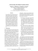
Figure 1: Continuous source transmitted through a diversity OFDM system with MDSQ.
Providing high-data-rate transmission is a key objective
for modern communication systems. Recently, orthogonal
frequency-division multiplexing (OFDM) has received a
considerable amount of interests for high-rate wireless com-
munications. Because OFDM increases the symbol duration
and transmitting data in parallel, it has become one of the
most effective modulation techniques for combating multi-
path delay spread over mobile wireless channels.
In this paper, we consider the problem of transmitting a
continuous source through an OFDM system over parallel
frequency-selective fading channels. The source signals are
quantized and encoded by an MDSQ, resulting in two cor-
related descriptions. These two descriptions are then modu-
lated by OFDM and sent through two parallel fading chan-
nels. At the receiver, a blind turbo receiver is developed for
joint OFDM demodulation and MDSQ decoding. Transfor-
mation of the extrinsic information of the two descriptions
are exchanged between each other to improve system per-
formance. The transformation is in terms of a transforma-
tion matrix which describes the correlation between the two
descriptions. Another novelty in this paper is the derivation
of a blind detector based on a Bayesian formulation and se-
quential Monte Carlo (SMC) techniques for the differentially
encoded OFDM system. Being soft-input and soft-output in
nature, the proposed SMC detector is capable of exchang-
ing the so-called extrinsic information with the other com-
ponent in the above turbo receiver, successively improving
the overall receiver performance.
For a practical communication system, channel coding is
usually applied to improve the reliability of the system. In this
paper, we also treat a channel-coded OFDM system, where
each stream of the source description is channel encoded and
then OFDM modulated before being sent to the channel. At
the receiver, a novel blind turbo receiver is developed for joint
demodulation, channel decoding, and source decoding.
The rest of this paper is organized as follows. In Section 2,
the diversity of an OFDM system with an MDSQ encoder
is described. In Section 3, the turbo receiver is discussed for
theMDSQencodedOFDMsystem.InSection 4 ,wedevelop
an SMC algorithm for blind symbol detection of OFDM sys-
tems. A turbo receiver for a channel-coded OFDM system
is derived in Section 5. Simulation results are provided in
Section 6, and a brief summary is given in Section 7.
2. SYSTEM DESCRIPTION
We consider transmitting a continuous source through a
diversity OFDM system. The diversity of an OFDM sys-
temismadeupoftwoN-subcarrier OFDM systems, sig-
nalling through two parallel frequency-selective fading chan-
nels. Such a parallel channel structure was first introduced in
[9]. A block diagram of the system is shown in Figure 1.A
sequence of continuous sources {S( j)} is encoded by a mul-
tiple description scalar quantizer (MDSQ), resulting in two
sets of equal-length indices {(I
1
( j), I
2
( j))},where j denotes
the sequence order. The detailed MDSQ encoder will be dis-
cussed in Section 2.1. These indices can be further described
in a binary sequence {(x
1
n
, x
2
n
)} with the order denoted by n.
The bit interleavers π
1
and π
2
are used to reduce the influ-
ence of error bursts at the input of the MDSQ decoder. After
the interleaved bits {a
1
n
}, {a
2
n
} are modulated by OFDM, we
use the parallel concatenated transmission scheme shown in
Figure 1; that is, one description of the source is transmit-
ted through one channel and the other description is trans-
mitted through another channel. At the receiver, the OFDM
demodulators, which will be discussed in Section 4, generate
soft information, which is then exchanged between the two
OFDM detectors in the form of aprioriprobabilities of the
information symbols. Next, we will focus on the structure of
the MDSQ encoder and the diversity OFDM system.
2.1. Multiple description scalar quantizer
2.1.1. Multiple description scalar quantizer
for diversity on/off channels
The multiple description scalar quantizer (MDSQ) is a sca-
lar quantizer designed for the channel model illustrated
Multiple Description Codes over OFDM 143
S(j)
Quantizer
q(·)
l( j)
Assignment
α(·)
I
1
( j)
I
2
( j)
Side
decoder 1
Central
decoder
Side
decoder 2
MDSQ encoder MDSQ decoder
Figure 2: Conventional MDSQ in a diversity system.
1
2
3
4
5
6
7
8
(a)
13
245
679
81011
12 13 15
14 16 17
18 19 21
20 22
(b)
135
26810
4 7 11 12 14
9 13161719
15 18 21 23 25
20 22 26 28 30
24 27 31 32
29 33 34
(c)
1234 ··· N − 1 N
(d)
Figure 3: MDSQ index assignment for R = 3. A quantized source sample l(j) ∈{1, 2, , N} is mapped to a pair of indices (I
1
( j),I
2
( j)) ⊂ C
composed of its associated row and column determined by the assignment α(·). (a) Assignment with N = 8. (b) Assignment w ith N = 22.
(c) Assig nment with N = 34. (d) Quantizer.
in Figure 2. The channel model consists of two channels
that connect the source to the destination. Either channel
may be broken or lossless at any time. The encoder of an
MDSQ sends information over each channel at a rate of
R bits/sample. Based on the decoder structure shown in
Figure 2, the objective is to design an MDSQ encoder so as
to minimize the average distortion when both channels are
lossless (center distortion), subject to a constraint on the av-
erage distortion when only one channel is lossless (side dis-
tortion).
Next, we give a brief summary of the MDSQ design
presented in [2]. Denote an index set I ={1, 2, , M},
where M = 2
R
.LetC ⊂ I × I and |C|=N ≤ M
2
.
The MDSQ encoder consists of an N-level quantizer q(·):
R →{1, 2, , N} followed by index assignment α(·):
{1, 2, , N}→C. Note that N is both the size of C and
the number of the quantization levels. Specifically, a source
sample S( j) is mapped to an index l( j) ∈{1, 2, , N} by the
quantizer q(·), which is further mapped to a pair of indices
(I
1
( j), I
2
( j)) ⊂ C by the assignment α(·).
Assume a uniform quantizer. The main issue in MDSQ
design is the choice of the set C, and the index assign-
ment α(·). Following [2], an example of good assignment
for R = 3 bits/sample is illustrated in Figure 3. We assume
that the cells of a quantizer are numbered 1, 2, , N, in in-
creasing order from left to right as shown in Figure 3d.In-
tuitively, with a larger set C, center distortion will be im-
proved at the expense of degraded side distortion. With the
same size of the set C, the center distortion is fixed, and a
diagonal-like assignment is preferred to minimize the side
distortion.
2.1.2. Multiple description scalar quantizer
for diversity fading channels
Although MDSQ was originally designed for diversity era-
sure channels, it provides a possible solution that combines
source coding and channel coding to exploit the diversity
provided by communication systems. Next, we consider the
application of MDSQ techniques in diversity fading chan-
nels.
At the transmitter, we apply the MDSQ encoder a s the
conventional (cf. Figure 2). For each continuous source S( j),
a pair of indices (I
1
( j), I
2
( j)) is generated by the MDSQ, and
is further mapped to binary bits
{x
1
n
, x
2
n
}
jR
n=( j−1)R+1
. Recall that
R denotes the bit-length of each description. At the receiver,
144 EURASIP Journal on Wireless Communications and Networking
OFDM modulator
a
i
n
QPSK
mod
d
i
k
Differ-
ential
encoder
S/P
Z
i
k
IDFT
Guard
interval
insertion
P/S
Pulse
shape
filter
Channel
h
i
(t)
Front-end processing
+
AWG N
ν
i
(t)
Y
i
k
DFT
Guard
interval
removal
S/P
Match
filter
Figure 4: Block diagram of a baseband OFDM system.
instead of using the side decoder and central decoder, a soft
MDSQ decoder is employed for MDSQ over fading channels.
It is assumed that a soft demodulator is available at the re-
ceiver, which generates the a posteriori symbol probability for
each bit x
i
n
,
Λ
i
[n] log
P
x
i
n
= 1 | Y
P
x
i
n
= 0 | Y
,(1)
where Y denotes the received signal which is given by (3).
Based on this posterior information, the soft MDSQ decod-
ing rule is given by
ˆ
I
1
( j),
ˆ
I
2
( j)
= arg max
(l,m)∈C
P
I
1
( j) = l |
Λ
1
[n]
n
· P
I
2
( j) = m |
Λ
2
[n]
n
,
(2)
which maximizes the posterior probability of the indices sub-
ject to a code structure constraint, that is, (I
1
( j), I
2
( j)) ∈ C.
2.2. Signal model for diversity OFDM system
Consider an OFDM system with N-subcarriers signaling
through a frequency-selective fading channel. The channel
response is assumed to be constant during one symbol du-
ration. The block diagram of such a system is shown in
Figure 4. The diversity OFDM system is just the parallel con-
catenation of combination of two such OFDM systems.
The binary information data
{a
i
n
}
n
are g rouped and
mapped into multiphase signals, w h ich take values from a
finite alphabet set A ={β
1
, , β
|A|
}. In this paper, QPSK
modulation is employed. The QPSK signals {d
i
k
}
N−2
k=0
are
differentially encoded to resolve the phase ambiguity in-
herent in any blind receiver, and the output is given by
Z
i
k
= Z
i
k−1
d
i
k
. These differentially encoded symbols are
then inverse DFT transformed. A guard interval is inserted
to prevent possible interference between OFDM frames.
After pulse shaping and parallel-to-serial conversion, the
signals are transmitted through a frequency-selective fading
channel. At the receiver end, after matched-filtering and re-
moving the guard interval, the sampled received signals
are sent to a DFT block to demultiplex the multicarrier
signals.
For the ith OFDM system with proper cyclic extensions
and proper sample timing, the demultiplexing sample of the
kth subcarrier can be expressed as [10]
Y
i
k
= Z
i
k
H
i
k
+ V
i
k
, k = 0, 1, , N − 1; i = 1, 2, (3)
where V
i
k
∼ N
c
(0, σ
2
) is the i.i.d. complex Gaussian noise
and H
i
k
is the channel frequency response at the kth sub-
carrier. Using the fact that H
i
k
can be f urther expressed as a
DFT transformation of the channel time response, the signal
model (3)becomes
Y
i
k
= Z
i
k
w
H
f
(k)h
i
+ V
i
k
, k = 0, 1, , N − 1; i = 1, 2, (4)
where h
i
= [h
i
0
, h
i
1
, , h
i
L−1
]
T
contains the time responses of
all L taps; L
=τ
m
∆
f
+1 denotes the maximum number
of resolvable taps, with τ
m
being the maximum multipath
spread and ∆
f
being the tone spacing of the carriers; and
w
f
(k)
= [1, e
−
2πk/N
, , e
−
2πk(L−1)/N
]
T
contains the corre-
sponding DFT coefficients.
3. TURBO RECEIVER
The receiver under consideration is an iterative receiver
structure as shown in Figure 5. It consists of two blind
Bayesian OFDM detectors, which compute the soft infor-
mation for the corresponding descriptions. At the output
of the blind detector, information about one description is
transferred to the other based on the existence of correla-
tion between the two descriptions. Such information trans-
fer is then repeated between the two blind detectors to im-
prove the system performance. Next, we will focus on the
operation on the first description to illustrate the iterative
procedure.
Multiple Description Codes over OFDM 145
Y
1
Blind OFDM
detector 1
{Λ
1
[k]}
+
−
{λ
1
[k]}
−1
1
Information
transfer
2
{λ
21
[k]}
{λ
12
[k]}
Blind OFDM
detector 2
{Λ
2
[k]}
+
−
{λ
2
[k]}
−1
2
Information
transfer
1
Y
2
Figure 5: Turbo decoding for multiple description over a diversity OFDM system; Π
i
and Π
−1
i
denote the interleaver and deinterleaver,
respectively, for the ith description.
3.1. Blind Bayesian OFDM detector
Denote Y
1
{Y
1
0
, Y
1
1
, , Y
1
N−1
} as the received signals for
the first description. The blind Bayesian OFDM detector for
the first description computes the a posteriori probabilities of
the information bits {a
1
n
}
n
,
Λ
1
[n]
= log
P
a
1
n
= 1 | Y
1
P
a
1
n
= 0 | Y
1
. (5)
The design of such a blind Bayesian detector will be discussed
later in Section 4 . For now, we assume the Bayesian detector
provides us such soft information, and focus on the structure
of the turbo receiver.
The a posteriori information delivered by the blind detec-
tor can be further expressed as
Λ
1
[n] = log
P
Y
1
| a
1
n
= 1
P
Y
1
| a
1
n
= 0
λ
1
[n]
+log
P
a
1
n
= 1
P
a
1
n
= 0
λ
p
21
[n]
. (6)
The second term in (6), denoted by λ
p
21
[n], represents the
apriorilog-likelihood ratio (LLR) of the bit a
1
n
fed from
detector 2. The superscript p indicates the quantity ob-
tained from the previous iteration. The first term in (6),
denoted by λ
1
[n], represents the extrinsic information de-
livered by detector 1, based on the received signals Y
1
, the
structure of signal model (4), and the aprioriinforma-
tion about all other bits {a
1
l
}
l=n
. The extrinsic information
{λ
1
[n]} is transformed into aprioriinformation {λ
p
12
[n]} for
bits {a
2
n
}
n
. This information transformation procedure is de-
scribed next.
3.2. Information transformation
Assume that {a
i
n
}
n
is mapped to {x
i
n
}
n
after passing through
the ith deinterleaver Π
−1
i
,withx
i
n
a
i
π
i
(n)
. To transfer the
information from detector 1 to detector 2, the following steps
are required.
(1) Compute the bit probability of the deinterleaved bits
P
x
1
n
= 1
=
e
λ
1
[π
1
(n)]
1+e
λ
1
[π
1
(n)]
. (7)
(2) Compute the probability distribution for the first in-
dex I
1
based on the deinterleaved bit probabilities
P
I
1
( j) = l
=
R
k=1
P
x
1
( j−1)R+k
= b
k
(l)
, l = 1, , |I|,
(8)
where {b
k
(l), k = 1, , R} is the binary representa-
tion for the index l ∈ I. Recall that R denotes the bit
length of each description.
(3) Compute the probability distribution for the second
index I
2
according to
P
I
2
(j) = m
=
|I|
l=1
P
I
2
( j) = m | I
1
( j) = l
· P
I
1
(j) = l
, m = 1, , |I|.
(9)
(4) Compute the bit probability that is associated with in-
dex I
2
( j),
P
x
2
( j−1)R+k
= 1
=
m:b
i
(m)=1
P
I
2
(j) = m
. (10)
(5) Compute the log likelihood of interleaved code bit
λ
12
π
2
(n)
= log
P
x
2
n
= 1
1 − P
x
2
n
= 1
. (11)
It is important to mention here that the key step is the calcu-
lation of the conditional probability P(I
2
( j) = m | I
1
( j) = l)
in (9). Hence, the proposed turbo receiver exploits the cor-
relation between the two descr iptions, which is measured by
the conditional probabilities in (9). From the discussion in
146 EURASIP Journal on Wireless Communications and Networking
the previous section, these conditional probabilities can be
easily obtained from the index assignment rule α(·) as shown
in Figure 3.
4. BLIND BAYESIAN OFDM DETECTOR
4.1. Problem statement
Denote Y
i
{Y
i
0
, Y
i
1
, , Y
i
N−1
}. The Bayesian OFDM re-
ceiver estimates the a posteriori probabilities of the informa-
tion symbols
P
d
i
k
= β
l
| Y
i
, β
l
∈ A; k = 1, , N − 1, (12)
based on the received signals Y
i
and the apriorisymbol prob-
abilities of {d
i
k
}
N−1
k=1
, without knowing the channel response
h
i
. Assume the bit a
i
n
is mapped to symbol d
i
κ(n)
.Basedon
this symbol a posteriori probability, the LLR of the code bit
as required in (5)canbecomputedby
Λ
i
[n] log
P
a
i
n
= 1 | Y
i
P
a
i
n
= 0 | Y
i
= log
β
l
∈A:d
i
κ(n)
=β
l
,a
i
n
=1
P
d
i
κ(n)
= β
l
| Y
i
β
l
∈A:d
i
κ(n)
=β
l
,a
i
n
=0
P
d
κ(n)
= β
l
| Y
i
.
(13)
Assume that the unknown quantities h
i
, Z
i
{Z
i
k
}
N−1
k
=1
are independent of each other and have aprioridistribution
p(h
i
)andp(Z
i
), respectively. The direct computation of (12)
is given by
P
d
i
k
= a
l
| Y
i
∝
Z
i
:d
i
k
=a
l
p
Y
i
| h
i
, Z
i
p
h
i
p
Z
i
dh
i
,
(14)
where p(Y
i
| h
i
, Z
i
) is a Gaussian density function [cf.
(4)].Clearly,thecomputationin(14) involves a very high-
dimensional integration which is certainly infeasible in prac-
tice. Therefore, we resort to the sequential Monte Carlo
method for numerical evaluation of the above multidimen-
sional integration.
4.2. SMC-based blind MAP detector
Sequential Monte Carlo (SMC) is a family of methodologies
that use Monte Carlo simulations to efficiently estimate the
a posteriori distributions of the unknown states in a dynamic
system [11, 12, 13]. In [14], an SMC-based blind MAP sym-
bol detection algorithm for OFDM systems is proposed. This
algorithm is summarized as follows.
(0) Initialization. Draw the initial samples of the chan-
nel vector from h
( j)
−1
∼ N
c
(0, Σ
−1
), for j = 1, , m.
All importance weights are initialized as w
( j)
−1
= 1,
j = 1, , m.
The following steps are implemented at the kth recursion
(k = 0, , N − 1) to update each weighted sample. For
j = 1, , m, the following hold.
(1) For each a
i
∈ A, compute the following quantities:
µ
( j)
k,i
= a
i
w
H
f
(k)h
( j)
k−1
,
σ
2( j)
k,i
= σ
2
+ w
H
f
(k)Σ
( j)
k−1
w
f
(k),
α
( j)
k,i
=
1
πσ
2(j)
k,i
exp
−
Y
k
− µ
( j)
k,i
2
σ
2(j)
k,i
· P
d
k
= a
i
Z
( j)∗
k−1
.
(15)
(2) Impute the symbol Z
k
.DrawZ
( j)
k
from the set A with
probability
P
Z
k
= a
i
| Z
( j)
k−1
, Y
k
∝ α
( j)
k,i
, a
i
∈ A. (16)
(3) Compute the importance weight:
w
( j)
k
= w
( j)
k−1
·
a
i
∈A
α
( j)
k,i
. (17)
(4) Update the a posteriori mean and covariance of the
channel. If the imputed sample Z
( j)
k
= a
i
in step (2),
set µ
( j)
k
= µ
( j)
k,i
, σ
2( j)
k
= σ
2( j)
k,i
; and update
h
( j)
k
= h
( j)
k−1
+
Y
k
− µ
(j)
k
σ
2( j)
k
ξ,
Σ
( j)
k
= Σ
( j)
k−1
−
1
σ
2( j)
k
ξξ
T
,
(18)
with
ξ Σ
( j)
k−1
w
f
(k)Z
( j)∗
k
. (19)
(5) Perform resampling when k is a multiple of k
0
,where
k
0
is the resampling interval.
4.3. APP detection
The above sampling procedure generates a set of random
samples
{(Z
( j)
k
, w
(j)
k
)}
m
j=1
, properly weighted with respect to
the distribution p(Z
k
| Y
k
). Based on these samples, an on-
line estimation and a delayed-weight estimation can be ob-
tained straightforwardly as
P
d
k
= β
l
| Y
k
∼
=
1
W
k
m
j=1
1
Z
( j)
k+1
Z
( j)∗
k
= β
l
w
( j)
k
,
P
d
k
= β
l
| Y
k+δ
∼
=
1
W
k+δ
m
j=1
1
Z
( j)
k+1
Z
( j)∗
k
= β
l
w
( j)
k+δ
,
(20)
Multiple Description Codes over OFDM 147
Diversity OFDM system
S(j)
MDSQ
encoder
& binary
mapping
b
1
m
1,1
c
1
m
Channel
encoder
x
1
n
1,2
a
1
n
Diff.
encoder
Z
1
k
Discrete-time
OFDM mod
Y
1
k
Y
i
k
= Z
i
k
w
H
f
(k)h
i
+ V
i
k
b
2
m
2,1
c
2
m
Channel
encoder
x
2
n
2,2
a
2
n
Diff.
encoder
Z
2
k
Discrete-time
OFDM mod
Y
2
k
Figure 6: MDSQ over a channel-coded diversity OFDM system.
where W
k
j
w
( j)
k
,and1(·) denotes the indicator func-
tion. Note that both of these two estimates are only approx-
imations to the a posteriori symbol probability P(d
k
= β
l
|
Y
N−1
).
We next propose a novel APP estimator, where the chan-
nel is estimated as a mixture vector, based on which the sym-
bol APPs are then computed. Specifically, we have
p
h | Y
N−1
=
1
W
N−1
m
j=1
p
h | Y
N−1
, Z
( j)
N−1
N
c
(h
(j)
N−1
,Σ
(j)
N−1
)
·w
( j)
N−1
. (21)
The symbol a posteriori probability is then given by
P
d
k
= β
l
| Y
N−1
=
P
d
k
= β
l
| Y
N−1
, h
p
h | Y
N−1
dh
=
P
d
k
= β
l
| Y
N−1
, h
×
1
W
N−1
m
j=1
p
h | Y
N−1
, Z
( j)
N−1
· w
( j)
N−1
dh
=
1
W
N−1
m
j=1
w
( j)
N−1
·
P
d
k
= β
l
| Y
N−1
, h
· p
h | Y
N−1
, Z
( j)
N−1
dh
∝
1
W
N−1
m
j=1
w
( j)
N−1
·
P
d
k
= β
l
Z
k
Z
∗
k−1
=β
l
P
Y
k
k−1
| Z
k
k−1
, h
· p
h | Y
N−1
, Z
( j)
N−1
dh
,
(22)
where Y
k
k−1
[Y
k−1
, Y
k
]
T
, Z
k
k−1
[Z
k−1
, Z
k
]
T
. Note that the
integral within (22) is an integral of a Gaussian pdf with re-
spect to another Gaussian pdf. The resulting distribution is
still Gaussian, that is,
P
Y
k
k−1
| Z
k
k−1
, h
· p
h | Y
N−1
, Z
( j)
N−1
dh
∼ N
c
µ
k, j
Z
k
k−1
, Σ
k, j
Z
k
k−1
,
(23)
with mean and variance given, respectively, by
µ
k, j
Z
k
k−1
=
µ
k, j
Z
k
µ
k−1, j
Z
k−1
,withµ
k, j
(x) xw
H
k
h
( j)
N−1
,
(24)
Σ
k, j
Z
k
k−1
=
σ
2
k, j
0
0 σ
2
k−1, j
,withσ
2
k, j
w
H
k
Σ
( j)
N−1
w
k
+ σ
2
.
(25)
Equations (24)and(25) follow from the fact that condi-
tioned on the channel h, Y
k
and Y
k+1
are independent. The
symbol a posteriori probability can then be computed in a
close form as
P
d
k
= β
l
| Y
N−1
≈
m
j=1
Z
k
Z
∗
k−1
=β
l
w
( j)
N
·
P
d
k
= β
l
σ
2
k, j
+ σ
2
k−1, j
exp
−
Y
k
− µ
k, j
Z
k
2
σ
2
k, j
−
Y
k−1
− µ
k−1, j
Z
k−1
2
σ
2
k−1, j
.
(26)
5. CHANNEL-CODED SYSTEMS
Although the MDSQ introduces some redundancy to the sys-
tem, it has limited capability for error correction. In order to
improve the system reliability, we next consider introducing
channel coding to the proposed MDSQ system.
A block diagram of an MDSQ system over a channel-
coded diversity OFDM system is shown in Figure 6.Astream
of source signal
{S( j)}
j
is MDSQ encoded, resulting in two
sets of indices {I
1
( j), I
2
(j)}
j
. Binary descriptions of these
148 EURASIP Journal on Wireless Communications and Networking
Inner loop
1,2
+
−
Y
1
OFDM
detector
{Λ
1
[k]}
+
−
{λ
1
[k]}
−1
1,2
Channel
decoder
+
−
−1
1,1
Inform
transfer
{λ
21
[k]}
1,2
Soft CH
encoder
1,1
{λ
12
[k]}
2,2
Soft CH
encoder
2,1
Y
2
OFDM
detector
{Λ
2
[k]}
+
−
{λ
2
[k]}
−1
2,2
Channel
decoder
+
−
−1
2,1
Inform
transfer
2,2
+
−
Inner loop
Figure 7: Turbo decoding for MDSQ over a channel-coded diversity OFDM system.
indices, {b
1
m
, b
2
m
}
m
, are then channel encoded and OFDM
modulated. There are two sets of bit interleavers in the sys-
tem: one set, named {Π
i,1
}
2
i=1
, is applied between the MDSQ
encoder and channel encoder; the other set, named {Π
i,2
}
2
i=1
,
is applied between the channel encoder and OFDM modula-
tor.
At the receiver, a novel blind iterative receiver is devel-
oped for joint demodulation, channel decoding, and MDSQ
decoding. The receiver structure, as shown in Figure 7,con-
sists of two loops of iterative operations. For each descrip-
tion, there is an inner loop (iterative procedure) for joint
OFDM demodulation and channel decoding. At the outer
loop, soft infor mation of the coded bits is exchanged between
the two inner loops to exploit the correlations between the
two descriptions. Next, we discuss the operation of both the
inner loop and the outer loop.
Inner loop: joint OFDM demodulation
and channel decoding
We consider a subsystem of the original MDSQ system,
which consists of the channel coding and OFDM modula-
tion for only one source description. Since the combina-
tion of a differential encoder and OFDM system acts as an
inner encoder, the above subsystem is a typical serial con-
catenated code, and an iterative (turbo) receiver can be de-
signed for such a system, which is denoted as the inner loop
part in Figure 7. It consists of two stages: the SMC OFDM
detector developed in the previous sections, followed by a
MAP channel decoder [15]. The two stages are separated
by a deinterleaver and an interleaver. Note that both the
SMC OFDM detector and the MAP channel decoder can in-
corporate the aprioriprobabilities and output a posteriori
probabilities of the code bits
{a
i
n
}
n
, that is, they are soft-
input and soft-output algorithms. Based on the turbo prin-
ciple, extrinsic information of the channel-coded bits can be
exchangediterativelybetweentheSMCOFDMdetectorand
the MAP channel decoder to improve the performance of the
subsystem.
Outer loop: exploiting the correlation
between the two descriptions
In Section 3, an iterative receiver was proposed for joint
MDSQ decoding and OFDM demodulation. Extrinsic in-
formation from one description is transfor med into the
soft information for the other description, a nd is fed into
the OFDM demodulator as the aprioriinformation. For
channel-coded MDSQ systems, similar approaches can be
considered to exploit the correlation between the two de-
scriptions. As shown in Figure 7, the MAP channel decoder
incorporates the aprioriinformation for the channel-coded
bits, and outputs the a posteriori probability of both channel-
coded bits and uncoded bits. On the other hand, the OFDM
detector incorporates and produces as output only the soft
information for the channel-coded bits. Taking into account
that only uncoded bits will be considered in the MDSQ
decoder, the inner loop, when considered as one unit op-
eration, is a SISO algorithm that incorporates the apriori
information of the channel-coded bits, and produces the
output a posteriori information of the uncoded bits. Al-
together, the two inner loops constitute a turbo structure
in parallel, and the transferred soft information provided
by the information transformation block (IF-T) can be ex-
changed iteratively between the two inner loops. This itera-
tive procedure is the outer loop of the system, which aims
at further improving the system performance by exploiting
the correlation between the two descriptions. It is shown
in Section 3 that this correlation can be measured by the
probability tr a nsformation matrix, and adopted by the IF-
T block. For the outer loop, the soft output of the inner
loop can be used directly as the aprioriinformation for
Multiple Description Codes over OFDM 149
the IF-T; the soft output of IF-T, however, must be trans-
formed before being fed into the inner loop as aprioriin-
formation. Specifically, a soft channel encoder by the BCJR
algorithm [15] is required to transform the soft information
of the uncoded bits into the soft information of the coded
bits.
6. SIMULATION RESULTS
In this section, we provide computer simulation results to
illustrate the performance of the turbo receiver for MDSQ
over diversity OFDM systems. In the simulations, the con-
tinuous alphabet source is assumed to be uniformly dis-
tributed on (−1, 1), a nd a uniform quantizer is applied. The
source range is divided into 8, 22, and 34 intervals. Two in-
dices are assigned to describe the source according the in-
dex assignment α(·) as shown in Figure 3, where each in-
dex is described with R = 3 bits. Assume the channel
bandwidth for each OFDM system is divided into N =
128 subchannels. Guard interval is long enough to pro-
tect the OFDM blocks from intersymbol interference due
to the delay spread. The frequency-selective fading chan-
nels are assumed to be uncorrelated. All L = 5tapsof
the fading channel are Rayleigh distributed with the same
variance, normalized such that E{
L−1
n=0
h
n
2
}=1, and
have delays τ
l
= l/∆
f
, l = 0, 1, , L − 1. For channel-
coded systems, a rate-1/2 constraint length-5 convolutional
code (with generators 23 and 35 in octal notation) is used.
The interleavers are generated randomly and fixed for all
simulations.
The blind SMC detector implements the algorithm de-
scribed in Section 4.2. The variance of the noise V
k
in (24)is
assumed known at the detector with values specified by the
given SNR. The SMC algorithm draws m = 50 Monte Carlo
samples at every recursion with Σ
−1
set to 1000I
L
.Twoquali-
ties were used in the simulation to measure the performance
of the SMC detector: bit error rate (BER) and word error rate
(WER). Here, the bit error rate denotes the information bit
error rate and word error rate denotes the error rate of the
whole data block transferred during one symbol duration.
On the other hand, mean square error (MSE) will be used to
measure the performance of the whole system.
Performance of the SMC detector
The blind SMC detector, as a SISO algorithm for OFDM
demodulation, is an important component of the proposed
turbo receiver. Next, we illustrate the performance of the
blind SMC detector. In Figure 8, the BER and WER perfor-
mance is plotted. In the same figure, we also plot the known
channel lower bound, where the fading coefficients are as-
sumed to be perfectly known to the receiver and a MAP re-
ceiver is employed to compute the a posteriori symbol prob-
abilities.
Although the SMC detector generates soft outputs in
terms of the symbol a posteriori probabilities, only hard de-
cisions are used in an uncoded system. However in a coded
system, the channel decoder, such as a MAP decoder, requires
302520151050
E
b
/N
0
(dB)
10
−4
10
−3
10
−2
10
−1
10
0
Bit error rate
Diff.demod.
CSI bound
SMC-online
SMC-delayed
SMC-APP
(a)
302520151050
E
b
/N
0
(dB)
10
−2
10
−1
10
0
Word error rate
Diff.demod.
CSI bound
SMC-online
SMC-delayed
SMC-APP
(b)
Figure 8: The (a) BER and (b) WER performance in an uncoded
OFDM system.
soft information provided by the demodulator. Next, we
examine the accurateness of the soft output provided by
theSMCdetectorinacodedOFDMscenario.InFigure 9,
the BER and WER performance for the information bits
is plotted. In the same figure, the known channel l ower
bound is also plotted. The MAP convolutional decoder is
employed in conjunction with the different detection algo-
rithms. It is seen from Figure 9 that the three SMC detec-
tor yield different perform ance after the MAP decoder be-
cause of the different quality of the soft information they
provide. Specifical ly, the APP detector achieves the best per-
formance.
Performance of turbo receiver for MDSQ system
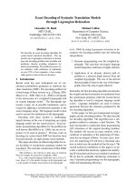
The performance of the turbo receiver is shown in Figures 10,
11,and12 for MDSQ systems with assignments 8, 22, and 34,
respectively, as in Figure 3. The SMC blind detector is em-
ployed. In each figure, the BER, WER, and MSE are plotted.
In the same figure, the quantization error bound s
2
/12, where
150 EURASIP Journal on Wireless Communications and Networking
14121086420
E
b
/N
0
(dB)
10
−4
10
−3
10
−2
10
−1
10
0
Bit error rate
Diff.demod.
CSI bound
SMC-online
SMC-delayed
SMC-APP
(a)
14121086420
E
b
/N
0
(dB)
10
−3
10
−2
10
−1
10
0
Word error rate
Diff.demod.
CSI bound
SMC-online
SMC-delayed
SMC-APP
(b)
Figure 9: The (a) BER and (b) WER performance in a channel-
coded OFDM system.
s denote the quantization interval, is also plotted in a dotted
line. It is seen that the BER and WER performance is signifi-
cantly improved at the second iteration, that is, 15 dB better
for N = 8, 4 dB better for N = 22 and 2 dB better for N = 34.
However, no significant gain is achieved by more iterations.
Note that the MSEs of the turbo receivers are very close to
the quantization error bound at high SNR. The quantiza-
tion error bound (5.2 × 10
−3
)forN = 8isachievedatabout
15 dB. However, much lower quantization error bounds are
achieved at hig her SNR by the turbo receiver with N = 22
and 34, that is, 6.9 × 10
−4
for N = 22 at SNR = 25 dB and
2.8 × 10
−4
for N = 34 at SNR = 30 dB. Moreover, due to
the different quantization error bounds determined by N and
the BER and the WER performance achieved by the turbo re-
ceiver , different MDSQ scheme should be chosen at different
SNRs to minimize the MSE. For example, the MDSQ with
N = 8 is superior to other assignments below SNR = 10 dB.
However, at SNR = 20 dB, the MDSQ scheme with N = 22
is the best choice among the three assignments considered in
this paper.
20151050
E
b
/N
0
(dB)
10
−5
10
0
Bit error rate
Quan8, 1st iteration
Quan8, 2nd iteration
Quan8, 3rd iteration
(a)
20151050
E
b
/N
0
(dB)
10
−5
10
0
Word error rate
Quan8, 1st iteration
Quan8, 2nd iteration
Quan8, 3rd iteration
(b)
20151050
E
b
/N
0
(dB)
−30
−20
−10
0
Mean square error (dB)
Quan8, 1st iteration
Quan8, 2nd iteration
Quan8, 3rd iteration
Quan8, quan. error bound
(c)
Figure 10: Performance of iterative receiver for the MDSQ system
with N = 8. (a) BER. (b) WER. (c) MSE.
Multiple Description Codes over OFDM 151
3020100
E
b
/N
0
(dB)
10
−4
10
−3
10
−2
10
−1
10
0
Bit error rate
Quan22, 1st iteration
Quan22, 2nd iteration
Quan22, 3rd iteration
(a)
3020100
E
b
/N
0
(dB)
10
−4
10
−3
10
−2
10
−1
10
0
Word error rate
Quan22, 1st iteration
Quan22, 2nd iteration
Quan22, 3rd iteration
(b)
3020100
E
b
/N
0
(dB)
−40
−30
−20
−10
0
Mean square error (dB)
Quan22, 1st iteration
Quan22, 2nd iteration
Quan22, 3rd iteration
Quan22, quan. error bound
(c)
Figure 11: Performance of iterative receiver for the MDSQ system
with N = 22. (a) BER. (b) WER. (c) MSE.
3020100
E
b
/N
0
(dB)
10
−4
10
−3
10
−2
10
−1
10
0
Bit error rate
Quan34, 1st iteration
Quan34, 2nd iteration
Quan34, 3rd iteration
(a)
3020100
E
b
/N
0
(dB)
10
−3
10
−2
10
−1
10
0
Word error rate
Quan34, 1st iteration
Quan34, 2nd iteration
Quan34, 3rd iteration
(b)
3020100
E
b
/N
0
(dB)
−40
−30
−20
−10
0
Mean square error (dB)
Quan34, 1st iteration
Quan34, 2nd iteration
Quan34, 3rd iteration
Quan34, quan. error bound
(c)
Figure 12: Performance of iterative receiver for the MDSQ system
with N = 34. (a) BER. (b) WER. (c) MSE.
152 EURASIP Journal on Wireless Communications and Networking
1086420
E
b
/N
0
(dB)
−40
−20
0
Mean square error (dB)
1st iteration
2nd iteration
3rd iteration
4th iteration
Quan. error bound
(a)
1086420
E
b
/N
0
(dB)
10
−3
10
−2
10
−1
10
0
Bit error rate
1st iteration
2nd iteration
3rd iteration
4th iteration
(b)
1086420
E
b
/N
0
(dB)
10
−3
10
−2
10
−1
10
0
Bit error rate
1st iteration
2nd iteration
3rd iteration
4th iteration
(c)
1086420
E
b
/N
0
(dB)
10
−2
10
−1
10
0
Word error rate
1st iteration
2nd iteration
3rd iteration
4th iteration
(d)
1086420
E
b
/N
0
(dB)
10
−2
10
−1
10
0
Word error rate
1st iteration
2nd iteration
3rd iteration
4th iteration
(e)
Figure 13: Performance of iterative receiver for channel coded MDSQ system, with 1 iteration for inner loop and 4 iterations for outer loop.
(a) MSE. (b) BER of coded bits. (c) BER of information bits. (d) WER of coded bits. (e) WER of information bits.
Performance of turbo receiver for channel-coded
MDSQ system
Finally, we consider the performance of the channel-coded
MDSQ system discussed in Section 5.Performanceis
compared for systems with different iterative profiles.
Specifically, the BER, WER, and MSE performance for the
information bits and coded bits are plotted in Figures 13
and 14 for the 4-inner-loop and 1-outer-loop turbo receivers
and the 3-inner-loop and 2-outer-loop turbo receivers,
respectively. In the simulation, the source range is divided
into 22 intervals as shown in Figure 3b. It is seen that the
proposed turbo receiver structure can successively improve
the receiver performance through iterative processing.
Moreover, the quantization error bounds are achieved at
very low SNR, that is, 10 dB.
7. CONCLUSIONS
In this paper, we have proposed a blind turbo receiver for
transmitting MDSQ-coded sources over frequency-selective
fading channels. Transformation of the extrinsic informa-
tion of the two descriptions are exchanged between each
other to improve the system performance. A novel blind APP
OFDM detector, which computes the a posteriori symbol
Multiple Description Codes over OFDM 153
1086420
E
b
/N
0
(dB)
−40
−20
0
Mean square error (dB)
1st iteration
2nd iteration
3rd iteration
Quan. error bound
(a)
1086420
E
b
/N
0
(dB)
10
−3
10
−2
10
−1
10
0
Bit error rate
1st iteration
2nd iteration
3rd iteration
(b)
1086420
E
b
/N
0
(dB)
10
−3
10
−2
10
−1
10
0
Bit error rate
1st iteration
2nd iteration
3rd iteration
(c)
1086420
E
b
/N
0
(dB)
10
−2
10
−1
10
0
Word error rate
1st iteration
2nd iteration
3rd iteration
(d)
1086420
E
b
/N
0
(dB)
10
−2
10
−1
10
0
Word error rate
1st iteration
2nd iteration
3rd iteration
(e)
Figure 14: Performance of iterative receiver for channel-coded MDSQ system, with 2 iterations for inner loop and 3 iterations for outer
loop. (a) MSE. (b) BER of coded bits. (c) BER of information bits. (d) WER of coded bits. (e) WER of information bits.
probabilities, is developed using sequential Monte Carlo
(SMC) techniques. Being soft-input and soft-output in na-
ture, the proposed SMC detector is capable of exchanging
the so-called extrinsic information with other component
in the above tur bo receiver, and successively improving the
overall receiver performance. Finally, we have also treated
channel-coded systems, and a novel blind turbo receiver is
developed for joint demodulation, channel decoding, and
MDSQ decoding. Simulation results have demonstrated the
effectiveness of the proposed techniques.
REFERENCES
[1] A. E. Gamal and T. Cover, “Achievable rates for multiple de-
scriptions,” IEEE Trans. Inform. Theory,vol.28,no.6,pp.
851–857, 1982.
[2] V. Vaishampayan, “Design of multiple description scalar
quantizers,” IEEE Trans. Inform. Theory,vol.39,no.3,pp.
821–834, 1993.
[3] Y. Zhang, M. Motani, and H. Garg, “Wireless video transmis-
sion using multiple description codes combined with priori-
tized DCT compression,” in IEEE International Conference on
154 EURASIP Journal on Wireless Communications and Networking
Multimedia and Expo (ICME ’02) , vol. 1, pp. 261–264, Lau-
sanne, Switzerland, August 2002.
[4] L. Ozarow, “On a source coding problem with two transmit-
ters and three receivers,” Bell Labs Technical Journal, vol. 59,
no. 10, pp. 1909–1921, 1980.
[5] S M. Yang and V. Vaishampayan, “Low-delay communica-
tion for Rayleigh fading channels: an application of the multi-
ple description quantizer,” IEEE Trans. Commun., vol. 43, no.
11, pp. 2771–2783, 1995.
[6] J. Barros, J. Hagenauer, and N. Gortz, “Turbo cross decoding
of multiple descr iptions,” in Proc. IEEE International Con-
ference on Communications (ICC ’02), vol. 3, pp. 1398–1402,
New York, NY, USA, April 2002.
[7] N. Kamaci, Y. Altunbasak, and R. Mersereau, “Multiple de-
scription coding with multiple transmit and receive antennas
for wireless channels: the case of digital modulation,” in IEEE
Global Telecommunications Conference (GLOBECOM ’01),pp.
3272–3276, San Antonio, Tex, USA, November 2001.
[8] D. Sachs, R. Anand, and K. Ramchandran, “Wireless image
transmission using multiple-description based concatenated
codes,” in Proc. IEEE Data Compression Conference (DCC ’00),
p. 569, Snowbird, Utah, USA, March 2000.
[9] K. Balachandran and J. Anderson, “Mismatched decod-
ing of intersymbol interference using a parallel concatenated
scheme,” IEEE J. Select. Areas Commun.,vol.16,no.2,pp.
255–259, 1998.
[10] J J. van de Beek, O. Edfors, M. Sandell, S. K. Wilson, and
P. O. B
¨
orjesson, “On channel estimation in OFDM systems,”
in Proc. IEEE Vehicular Technology Conference (VTC ’95),pp.
815–819, Chicago, Ill, USA, July 1995.
[11] A. Doucet, N. de Freitas, and N. Gordon, Sequenti al Monte
Carlo in Practice, Springer-Verlag, New York, NY, USA, 2001.
[12] A. Doucet, S. Godsill, and C. Andrieu, “On sequential Monte
Carlo sampling methods for Bayesian filtering ,” Statistics and
Computing, vol. 10, no. 3, pp. 197–208, 2000.
[13] X. Wang, R. Chen, and J. Liu, “Monte Carlo signal processing
for wireless communications,” Journal of VLSI Signal Process-
ing, vol. 30, no. 1-3, pp. 89–105, 2002.
[14] Z. Yang and X. Wang, “A sequential Monte Carlo blind re-
ceiver for OFDM systems in frequency-selective fading chan-
nels,” IEEE Trans. Signal Processing, vol. 50, no. 2, pp. 271–280,
2002.
[15]L.Bahl,J.Cocke,F.Jelinek,andJ.Raviv, “Optimaldecod-
ing of linear codes for minimizing symbol error rate (Cor-
resp.),” IEEE Trans. Inform. Theory, vol. 20, no. 2, pp. 284–287,
1974.
Zigang Yang received the B.S. degree in
electrical engineering and applied math-
ematics in 1995, and the M.S. degree
in electrical engineering in 1998, both
from Shanghai Jiaotong University (SJTU),
Shanghai, China. In 2002, she got the Ph.D.
degree in electrical engineering from Texas
A&M University, College Station, Texas.
From 1999 till 2002, she was a Research As-
sistant with the Department of Electrical Engineering, Texas A&M
University. Currently, she is working as a system engineer at Texas
Instrument, Communication R&D Lab. Her research interests are
in the area of statistical signal processing and its applications, pri-
marily in digital communications.
Dong Guo received the B.S. degree in
geophysics and computer science from
China University of Mining and Technol-
ogy (CUMT), Xuzhou, China, in 1993,
and the M.S. degree in geophysics from the
Graduate School of Research Institute of
Petroleum Exploration and Development
(RIPED), Beijing, China, in 1996. In 1999,
he received the Ph.D. degree in applied
mathematics from Beijing University,
Beijing, China. In 2004, he received a second Ph.D. degree in
electrical engineering from Columbia University, New York. His
research interests are in the area of statistical signal processing and
communications.
Xiaodong Wang received the B.S. degree
in electrical engineering and applied math-
ematics (with the highest honors) from
Shanghai Jiao Tong University, Shanghai,
China, in 1992; the M.S. degree in electri-
cal and computer engineering from Purdue
University in 1995; and the Ph.D. degree in
electrical engineering from Princeton Uni-
versity in 1998. From July 1998 to Decem-
ber 2001, he was on the faculty of the De-
partment of Electrical Engineering, Texas A&M University. In Jan-
uary 2002, he joined the Department of Electrical Engineering,
Columbia University. Dr. Wang’s research interests fall in the gen-
eral areas of computing, signal processing, and communications.
Among his publications is a recent book entitled Wireless Commu-
nication Systems: Advanced Techniques for Signal Reception, pub-
lished by Prentice Hall. Dr. Wang has received the 1999 NSF CA-
REER Award. He has also received the 2001 IEEE Communica-
tions Society and Information Theory Society Joint Paper Award.
He currently serves as an Associate Editor for the IEEE Transac-
tions on Signal Processing, the IEEE Transactions on Communi-
cations, the IEEE Transactions on Wireless Communications, and
IEEE Transactions on Information Theory.