Ebook_ Data Centers.pdf
Bạn đang xem bản rút gọn của tài liệu. Xem và tải ngay bản đầy đủ của tài liệu tại đây (9.17 MB, 62 trang )
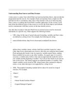
A holistic view of the data center
and the opportunities to enhance
its infrastructure to meet current
and future demands
DATA CENTERS
For over 40 years, CommScope’s highly trained specialists have
partnered with our customers to identify, design and build specialized
solutions for data centers. Drawing upon this wealth of expertise
and experience, CommScope developed this eBook to provide a
holistic overview of the data center and share guidance about how to
navigate through the ever-increasing challenges faced by data center
managers both now and in the future.
Explore the chapters to find out tips, answers and insights to demystify the technology, untangle
the complexity and accelerate time to market so you can identify the challenges—and opportunities—
in your own data center.
1. Data center standards
6.Fiber selection
2.Multi tenant data centers
7.Optical distribution frames
3.Data center topologies and architectures
8.Automated infrastructure management
4.High Speed Migration
9.Designing for fiber TAPs
5.Multisource agreements
Conclusion and authors
DATA
CENTERS
Chapter 1
Data center standards
Data center
standards
Chapter 1
Setting the standards for higher speeds
Data centers and their contents must adhere to a wide range of standards, ranging from local building codes to
guidelines from the American Society of Heating, Refrigerating and Air-Conditioning Experts (ASHRAE) on cooling to
a number of requirements placed on the IT equipment. There are also a number of standards related to the structured
cabling infrastructure that serves as the platform for IT equipment in the data center.
CommScope monitors data center trends and
participates in standards organizations to help data
center operators stay ahead of the industry. Given
the relentless growth in data traffic and the need to
provide high-bandwidth, low-latency connections,
there has been a tremendous amount of activity within
the standards bodies to define higher speeds. It is
important to keep up with the latest developments
to ensure the cabling infrastructure can support these
higher speeds with minimal disruption.
Server to Switch Connectivity
www.commscope.com
4
1 | Data center standards
How the standards define data center cabling
There are two main types of standards relevant to data center cabling infrastructure:
Application Standards
Applications standards define the application that will run on the
cabling infrastructure. There are three applications standards that
are the most commonly deployed in data centers.
IEE 802.3
(Ethernet standards) have been particularly
active, and currently have draft standards
underway for applications up to 400 Gb/s.
INCITS T11
(Fibre Channel) covers storage area networks
(SANs), with published standards for up to 128
Gb/s with a roadmap out to 1 Tb/s.
Infiniband™
Infiniband Trade Association is used primarily
for high-performance computing applications,
with a roadmap with options for up to 600 Gb/s.
Cabling Standards
Cabling standards provide more detail around the physical media
and define the channel that supports the applications. There are
three main cabling standard bodies.
TIA®
CENELEC
ISO/IEC
North America
Europe
Global
Each of these groups has a general standard which defines structured
cabling, as well as a standard specifically for data center applications
to reflect the need for higher speeds, increased density and an array
of architectures. While there are differences between these standards,
there is agreement around the minimum recommended cabling
categories and connector types.
Data center
standard
Fiber
Applications standards also define the distance that an application
can operate over a given media type. For example, under IEEE
802.3an, 10GBASE-T can operate at up to 100 meters over
Category 6A cabling.
Connectors
TIA®
CENELEC
ISO/IEC
TIA-942-B
EN 50173-5
ISO-IEC 11801-5
OM4
OM3
OM3
OS1a
OS2
OS2
LC (≤ 2 fibers)
MPO (≥ 2 fibers)
In addition to EN50173-5, CENELEC has also developed the EN 50600-2-4 standard
“Telecommunication Cabling Infrastructure”. It focuses primarily on design requirements for
the different DC availability classes with strong emphasis on migration and growth.
www.commscope.com
5
1 | Data center standards
RESOURCES
Keep up with the standards
to future-proof the data center
White Paper
Data Center Application Standards
Reference Guide - Networking and Storage
Standards updates
CommScope Quarterly Standards Advisor
White Paper
Data Center Cabling Design Fundamentals:
Telecommunication Cabling
Infrastructure Requirements
Since data center cabling infrastructure
will likely need to support multiple generations
of equipment and speeds in the future, keeping
up with the latest standards developments is critical.
For new builds, it is important to deploy the highest
bandwidth cabling as per the data center cabling standards.
www.commscope.com
6
DATA
CENTERS
Chapter 2
Multi tenant data centers
Chapter 2
Multi tenant
data centers
Freeing enterprises to focus
on their core business
With more than 130 million square feet of white space, multi
tenant data centers (MTDCs) are one of the fastest-growing
segments in the data center industry. Expanding at a rate of
16 percent annually, MTDCs enable enterprises and service
providers to outsource their data center facilities. By leasing
third-party data center whitespace, enterprises can remain
focused on their core business while enjoying optimal data
center availability, reliability and cost control.
As a leading provider of multi tenant data center infrastructure solutions, CommScope has
developed considerable expertise in this space, helping both operators and tenants maximize the
value of these flexible, cost-effective facilities.
www.commscope.com
8
2 | Multi tenant data centers
KEY ADVANTAGES
Flexibility
Multi tenant data center infrastructure makes advanced technology such as cloud computing and virtualized data
centers available to small- and mid-sized businesses while also allowing easy expandability as the business grows.
Reliability
Multi tenant data centers provide their own technicians to maintain the infrastucture and ensure that hosted
functions operate at peak efficiency at all times. Multi tenant data center operators provide service level agreements
(SLAs) to tenant clients to ensure commitment to uptime and operational parameters. Multi tenant data center
operators typically offer 2N, N+1, N and hybrid mesh solutions for power redundancy with multiple POPs (point of
presence)/ POEs (point of entrance), as well as multiple metro/WAN connectivity providers to provide redundancies
that increase reliability. This enables clients to balance their redundancy/reliability needs against their cost options.
Some clients may require lower levels of reliablility for certain applications, such as deploying a lab environment;
Multi tenant data centers can match the reliability requirements to specific user requirements.
Reduced Latency
By providing direct connectivity to service providers, content providers, cloud providers, high-frequency traders,
financial transaction and peering partners also co-located at the multi tenant data center, latency can be
significantly reduced.
www.commscope.com
9
2 | Multi tenant data centers
KEY ADVANTAGES
Savings
By outsourcing data center services instead of building, hosting, maintaining and upgrading them themselves,
multi tenant data center tenants can realize significant OpEx and CapEx savings. Most companies are not in the
business of building and operating data centers. The expertise and efficiencies gained by multiple builds and
design iterations have enabled Multi tenant data center operators to optimize their designs and operational
efficiencies. Multi tenant data center operators can not only build a data center more cost-efficiently but are
also able to operate it more cost-effectively, as well. Building a traditional data center is a significant capital
expense for enterprises; Multi tenant data center operators offer conversion from CapEx to OpEx by leasing the
data center to the client, and also offer savings from tenant improvement or asset amortization. Enabling direct
connection between enterprises, vendors, content providers and cloud providers in the same facility eliminates
the need for metro/WAN connections that have backhaul and bandwidth charges. Multi tenant data centers offer
clients the ability to scale as they grow, and to deploy assets on a just in time basis.Most leases run from three
to 15 years, which gives the customer the ability to dynamically manage their business versus trying to over-plan
and build a traditional data center that is an up to 30-year depreciating asset.
Security
A multi tenant data center offers multiple levels of security against external threats plus faster, more thorough recovery
from disaster situations. The initial layer of security is at the entry points of the facility or campus, which are usually
surrounded by high steel fences, gates and bollards, and equipped with a badge or biometric readers and security
personnel. The facilities themselves are designed to restrict accessibility while maintaining a discrete appearance. Inside,
there are security guards, restricted access and man traps that are designed to slow and restrict entry. Only authorized
personnel are allowed entry to designated areas via badge or biometric access. In addition, the entire campus is under
continuous monitoring via security cameras, and may often be subject to random security patrols.
www.commscope.com
10
2 | Multi tenant data centers
Factors to consider when choosing a multi tenant data center
The best multi tenant data center providers help clients through all stages of the project, from need assessment through migration through
operation. They have the core competencies to understand, meet and exceed clients requirements.
High-quality, robust mechanical, electrical, and data
transport infrastructure that performs optimally and
deploys quickly, allowing for fast, simple changes.
Physical layer management that supports the
tenant’s differentiated services and allows visibility
into the enterprise.
Scalability to readily expand capacity and functionality
under the same roof to meet increasing data center
demand as the tenant’s business grows. This includes
space, power and bandwidth scalability, and also the
ability to scale down should there be a shift in public
cloud utilization.
Direct access to cloud and content providers. Today’s
and tomorrow’s data centers are and will continue
to be connected with content and cloud providers in
an effort to support internal and external customers.
The ability to have direct access to these providers
improves latency and cost objectives.
Effective in-building wireless (IBW) service for tenants working
onsite, since data centers are often constructed with reinforced
materials that make IBW coverage difficult. Providing mobile
service to all mobile operators ensures that tenants have access,
ensuring their productivity and efficiency while they are onsite.
www.commscope.com
11
2 | Multi tenant data centers
When designing the cabling infrastructure for
deployment in an MTDC, it is critical that the infrastructure
be able to scale up and down, and adapt to technology changes.
It must be able to integrate peer, cloud and hybrid strategies, and must also
ensure that adequate space is allocated for horizontal and vertical cable management
so that moves, adds and changes can be carried out easily. There is often the temptation to
fully load server and switch cabinets without consideration of cable management. While this may reduce
the amount of leased rack space, it also greatly increases the risk of downtime due to manual error.
Proper cabling design, along with the use of an automated infrastructure management (AIM) system, can reduce this risk.
www.commscope.com
12
DATA
CENTERS
Chapter 3
Data center topologies
and architectures
Chapter 3
Data center topologies
and architectures
Creating a blueprint for better data center performance
A data center networking architecture—the layout of the cabling infrastructure and the way servers are connected to
switches—must strike a balance between reliability, performance, agility, scalability and cost. It must also support both
current and future applications and speeds.
Key factors in selecting a data center architecture include:
The size of the
current data center
Anticipated growth of
the data center
Whether it's a new
installation or an upgrade
of a legacy system
www.commscope.com
14
3 | Data center topologies and architectures
TOPOLOGIES
There are three main data center topologies in use today—and each has its advantages and
trade-offs. In fact, some larger data centers will often deploy two or even all three of these
topologies in the same facility.
1. CENTRALIZED
Main distribution
The centralized model is an appropriate topologies for smaller
data centers (under 5,000 square feet). As shown, there are
separate local area network (LAN)/ storage area network
(SAN) environments and each one has home run cabling that
goes to each of the server cabinets and zones. Each server
is effectively cabled back to the core switches, which are
centralized in the main distribution area.
This provides very efficient utilization of port switches
and makes it easier to manage and add components. The
centralized topology works well for smaller data centers but
does not scale up well, which makes it difficult to support
expansions. In larger data centers, the high number of
extended-length cable runs required causes congestion in the
cable pathways and cabinets, and increases cost. While some
larger data centers use zoned or top-of-rack topologies for
LAN traffic, they may also utilize a centralized architecture for
the SAN environments. This is especially true where the cost
of SAN switch ports is high and port utilization is important.
- Networking core
- Networking access
- SAN core
- Main cross-connect
Storage area network
(SAN) fiber optic
Server cabinet
Ethernet network
fiber optic or copper
Storage cabinet
www.commscope.com
15
3 | Data center topologies and architectures
2. ZONED
Main distribution
Zoned topology consists of distributed switching
resources. As shown below, the switches can be
distributed among end-of-row (EoR) or middleof-row (MoR) locations, with chassis-based
switches typically used to support multiple server
cabinets. This solution is recommended by the
ANS/TIA-942 Data Center Standards and is very
scalable, repeatable, and predictable. Zoned
architecture is usually the most cost-effective design,
providing the highest level of switch and port
utilization while minimizing cabling costs.
In certain scenarios, end-of-row switching provides
performance advantages. For example, the local area
network (LAN) ports of two servers (that exchange
large volumes of information) can be placed on the
same end-of-row switch, for low-latency port-toport switching. A potential disadvantage of endof-row switching is the need to run cable back to
the end-of-row switch. Assuming every server is
connected to redundant switches, this cabling can
exceed what is required in top-of-rack architecture.
- Networking core
- SAN core
- Main cross-connect
Storage area network
(SAN) fiber optic
Server cabinet
Ethernet network
fiber optic
Storage cabinet
Ethernet network
copper
Access switches
www.commscope.com
16
3 | Data center topologies and architectures
Main distribution
3. TOP OF RACK
- Networking core
- SAN core
- Main cross-connect
Top-of-rack (ToR) switching typically consists of two
or more switches placed at the top of the rack in
each server cabinet, as shown below. This topology
can be a good choice for dense one rack-unit (1RU)
server environments. All servers in the rack are cabled
to both switches for redundancy. The top-of-rack
switches have uplinks to the next layer of switching.
Top of rack significantly simplifies cable management
and minimizes cable containment requirements.
This approach also provides fast port-to-port
switching for servers within the rack and predictable
oversubscription of the uplink.
A top-of-rack design utilizes cabling more efficiently.
The tradeoffs are often an increase in the cost of
switches and the high cost for under-utilization
of ports. Top-of-rack switching may be difficult to
manage in large deployments, and there is also the
potential for overheating of local area network (LAN)
switch gear in server racks. As a result, some data
centers deploy top-of-rack switches in a middle-of-row
or end-of-row architecture to better utilize switch ports
and reduce the overall number of switches used.
Storage area network
(SAN) fiber optic
Server cabinet
Ethernet network
fiber optic
Storage cabinet
Ethernet network
copper
Access switches
www.commscope.com
17
3 | Data center topologies and architectures
ARCHITECTURES
1. MESH NETWORK
The mesh network architecture, often
referred to as a “network fabric,” or leafspine, consists of meshed connections
between leaf-and-spine switches. The
mesh of network links enables any-to-any
connectivity, with predictable capacity and
lower latency—making this architecture
well suited for supporting universal
“cloud services.” With multiple switching
resources spread across the data center,
the mesh network is inherently redundant
for better application availability. These
distributed network designs can be much
more cost-effective to deploy and scale
when compared to very large, traditional
centralized switching platforms.
WAN Carrier 1
Internet
ER
WAN Carrier 2
Carrier
Border leaf tier
MDA
Spine switch tier
ZDA
Leaf switch tier
EDA
Servers
www.commscope.com
18
3 | Data center topologies and architectures
2. THREE-TIER OR MULTI-TIER MODEL
The multi-tier architecture has been the
most commonly deployed model used
in the enterprise data center. This design
consists primarily of web, application and
database server tiers running on various
platforms, including blade servers, 1RU
servers and mainframes.
WAN Carrier 1
Internet
ER
WAN Carrier 2
Carrier
Edge/core layer
MDA
Aggregation layer
ZDA
Access layer
EDA
Servers
SAN director layer
EDA
Disk arrays
www.commscope.com
19
3 | Data center topologies and architectures
3. MESH POINT OF DELIVERY (PoD)
The mesh point of delivery (PoD) architecture
features multiple leaf switches interconnected
within in the PoDs, with spine switches
typically aggregated in a central main
distribution area (MDA). Among other
advantages, this architecture enables multiple
PoDs to connect efficiently to a super-spine
tier. Data center managers can easily add
new infrastructure to their existing three-tier
topology to support the low-latency eastwest data flow of new cloud applications.
Mesh PoD networks can provide a pool of
low-latency compute and storage for these
applications that can be added without
disrupting the existing environment
WAN Carrier 1
Internet
ER
WAN Carrier 2
Carrier
Edge/core leaf
MDA
Super spine tier
PoD full mesh
PoD full mesh
ZDA
(each row,
each hall)
Leaf mesh tier
EDA
(each hall)
Servers
www.commscope.com
20
3 | Data center topologies and architectures
WAN Carrier 1
Super spine architecture is commonly
deployed by hyperscale organizations
deploying large-scale data center
infrastructures or campus-style data centers.
Internet
ER
WAN Carrier 2
Carrier
Edge/core leaf
This type of architecture services huge
amounts of data passing east to west
across data halls.
MDA
Super spine tier
PoD full mesh
ZDA
PoD full mesh
Spine switches
(each row,
each hall)
Leaf switches
EDA
Computer/
Storage pods
(each hall)
Ethernet link
Ethernet / FCoE link
www.commscope.com
21
3 | Data center topologies and architectures
Data center equipment connection methods
There are two methods typically used to connect data center electronics via structured cabling: cross-connect and interconnect.
Cross-connect
A cross-connect uses patch cords or jumpers to connect cabling
runs, subsystems and equipment to connecting hardware at each
end. It enables connections to be made without disturbing the
electronic ports or backbone cabling. A cross-connect provides
excellent cable management and design flexibility to support future
growth. Designed for “any-to-any” connectivity, this model enables
any piece of equipment in the data center to connect to any other
regardless of location. A cross-connect also offers operational
advantages, as all connections for moves, add and changes are
managed from one location. The major disadvantage is higher
implementation costs due to increased cabling requirements.
Interconnect
An interconnect uses patch cords to connect
equipment ports directly to the backbone
cabling. This solution requires fewer
components and is, therefore, less expensive.
However, it reduces flexibility and introduces
additional risk, as users must directly access
the electronics ports in order to make the
connection. Therefore, CommScope generally
recommends utilizing cross-connects for
maximum flexibility and operational efficiency
in the data center.
www.commscope.com
22
3 | Data center topologies and architectures
Architecture for a higher-speed future
With newer technologies—25/50/100GbE, 32G and 128G Fibre Channel—
limitations on bandwidth, distance and connections are more stringent than with lower-speed legacy systems.
In planning the data center’s local area network (LAN)/storage area network (SAN) environment, designers must
understand the limitations of each application being deployed and select an architecture that will not only support current
applications but also have the ability to migrate to higher-speed future applications.
www.commscope.com
23
DATA
CENTERS
Chapter 4
High Speed Migration
Chapter 4
High Speed
Migration
Redesigning data center connectivity for a higher-speed future
To support the rapid growth of cloud-based storage and compute services, data centers are adapting their traditional
three-layer switching topologies to accommodate highly agile, low-latency performance. These new architectures resemble
“warehouse scale” facilities that are designed to support many different enterprise applications.
Spine switches
Leaf switches
Edge
devices
Edge
devices
Edge
devices
Edge
devices
Edge
devices
Edge
devices
Leaf-spine architectures, for example, create an optimized path for server-to server communication that can accommodate
additional nodes, as well as higher line rates, as the network grows. The meshed connections between leaf-and-spine
switches allow applications on any compute and storage device to work together in a predictable, scalable way regardless of
their physical location within the data center.
www.commscope.com
25