Báo cáo hóa học: " Space-Time Chip Equalization for Maximum Diversity Space-Time Block Coded DS-CDMA Downlink " doc
Bạn đang xem bản rút gọn của tài liệu. Xem và tải ngay bản đầy đủ của tài liệu tại đây (765.52 KB, 11 trang )
EURASIP Journal on Applied Signal Processing 2004:5, 740–750
c
2004 Hindawi Publishing Corporation
Space-Time Chip Equalization for Maximum
Diversity Space-Time Block Coded DS-CDMA
Downlink Transmission
Geert Leus
Faculty of Electrical Engineering, Mathemat ics, and Computer Science, Delft University of Technology,
Mekelweg 4, 2628CD Delft, The Netherlands
Email:
Frederik Petr
´
e
Wireless Research, Interuniversity Micro-Electronics Center (IMEC), Kapeldreef 75, 3001 Leuven, Belgium
Email:
Marc Moonen
Department of Electrical Engineering (ESAT), Katholieke Universiteit Leuven (K.U.Leuven),
Kasteelpark Arenberg 10, 3001 Leuven, Belgium
Email:
Received 24 December 2002; Revised 4 August 2003
In the downlink of DS-CDMA, frequency-selectivity destroys the orthogonality of the user signals and introduces multiuser in-
terference (MUI). Space-time chip equalization is an efficient tool to restore the orthogonality of the user signals and suppress
the MUI. Furthermore, multiple-input multiple-output (MIMO) communication techniques can result in a significant increase
in capacity. This paper focuses on space-time block coding (STBC) techniques, and aims at combining STBC techniques with the
original single-antenna DS-CDMA downlink scheme. This results into the so-called space-time block coded DS-CDMA downlink
schemes, many of which have been presented in the past. We focus on a new scheme that enables both the maximum multiantenna
diversity and the maximum multipath diversity. Although this maximum diversity can only be collected by maximum likelihood
(ML) detection, we pursue suboptimal detection by means of space-time chip equalization, which lowers the computational com-
plexity significantly. To design the space-time chip equalizers, we also propose efficient pilot-based methods. Simulation results
show improved performance over the space-time RAKE receiver for the space-time block coded DS-CDMA downlink schemes
that have been proposed for the UMTS and IS-2000 W-CDMA standards.
Keywords and phrases: downlink CDMA, space-time block coding, space-time chip equalization.
1. INTRODUCTION
Direct sequence code division multiple access (DS-CDMA)
has emerged as the predominant multiple access technique
for 3G cellular systems. In the downlink of DS-CDMA, or-
thogonal user signals are transmitted from the base station.
All these signals are distorted by the same channel when
propagating to the desired mobile station. Hence, when this
channel is frequency-selective, the orthogonality of the user
signals is destroyed and severe multiuser interference (MUI)
is introduced. Space-time chip equalization can then restore
the orthogonality of the user signals and suppress the MUI
[1, 2, 3, 4].
Multiple-input multiple-output (MIMO) systems, on the
other hand, have recently been shown to realize a significant
increase in capacity for rich scattering environments [5, 6, 7].
Both space division multiplexing (SDM) [8, 9]andspace-
time coding (STC) [10, 11, 12] are popular MIMO commu-
nication techniques. SDM techniques mainly aim at an in-
crease in throughput by transmitting different data streams
from the different transmit antennas. However, SDM typi-
cally requires as many receive as transmit antennas, which se-
riously impairs a cost-efficient implementation at the mobile
station. STC techniques, on the other hand, mainly aim at an
increase in performance by introducing spatial and tempo-
ral correlation in the transmitted data streams. As opposed
to SDM, STC supports any number of receive antennas, and
thus enables a cost-efficient implementation at the mobile
station. In this perspective, space-time block coding (STBC)
techniques, introduced in [11] for two transmit antennas and
Space-Time Chip Equalization 741
later generalized in [12]foranynumberoftransmitanten-
nas, are particularly appealing because they facilitate maxi-
mum likelihood (ML) detection with simple linear process-
ing. However, these STBC techniques have originally been
developed for signaling over frequency-flat channels, and do
not enable the maximum multiantenna and multipath diver-
sity present in frequency-selective channels. Therefore, im-
proved STBC techniques have recently been developed for
signaling over frequency-selective channels [13, 14, 15]. The
STBC technique proposed in [13] enables the maximum
multiantenna diversity, and although it is presented as a tech-
nique that provides the maximum multipath diversity, it is
not possible to prove it without any proper discussion on
how to treat the edge effects at the beginning and the end
of a burst. If the edge effects are handled by a cyclic prefix as
in [14], maximum multipath diversity is not guaranteed. On
the other hand, if the edge effects are handled by a zero post-
fix as in [15], maximum multipath diversity is guaranteed.
Up till now, research on STBC techniques has mainly
focused on single-user communication links. In this pa-
per, we aim at combining STBC techniques with the orig-
inal single-antenna DS-CDMA downlink scheme, resulting
into so-called space-time block coded DS-CDMA downlink
schemes. As an example, we mention the space-time block
coded DS-CDMA downlink schemes that have been pro-
posed for the UMTS and IS-2000 W-CDMA standards, both
special cases of the so-called space-time spreading scheme
presented in [16], which consists of a mixture of the original
single-antenna DS-CDMA downlink scheme and the STBC
technique of [12]. However, this scheme does not enable the
maximum multiantenna and multipath diversity present in
frequency-selective channels. A second example is the space-
time block coded DS-CDMA downlink scheme presented
in [17], which consists of the original single-antenna DS-
CDMA downlink scheme followed by the STBC technique
of [14]. However, this scheme only enables the maximum
multiantenna diversity but not the maximum multipath di-
versity (due to the fact that maximum multipath diversity
is not provided by the STBC technique of [14]). Therefore,
in this paper, we consider the space-time block coded DS-
CDMA downlink scheme that consists of the original single-
antenna DS-CDMA downlink scheme followed by the STBC
technique of [15]. This scheme enables both the maximum
multiantenna diversity and the maximum multipath diver-
sity (due to the fact that maximum multipath diversity is pro-
vided by the STBC technique of [15]). Although this max-
imum diversity can only be collected by ML detection, we
pursue suboptimal detection by means of space-time chip
equalization, which lowers the computational complexity
significantly. Note that this suboptimal detection technique
can also be applied to the STBC technique of [15]onitsown,
without combining it with the original single-antenna DS-
CDMA downlink scheme.
Assuming there are J transmit antennas, the straightfor-
ward way to implement space-time chip equalization is to
apply J space-time chip equalizers to recover the J t ransmit-
ted space-time block coded multiuser chip sequences, then
to apply space-time decoding to recover J subsequences of
the original multiuser chip sequence, and finally, to perform
simple despreading. Since this comes down to an equaliza-
tion problem with J sources, we need J +1chipratesam-
pled outputs at each mobile station for a finite-length zero-
forcing (ZF) solution to exist (i.e., J + 1 receive antennas
if the antennas are sampled at chip rate). However, we will
show that the space-time chip equalization and space-time
decoding operations can be swapped, which allows us to first
apply space-time decoding, then to apply J space-time chip
equalizers to recover J subsequences of the original multiuser
chip sequence, and finally, to perform simple despreading.
Since this comes down to J equalization problems with only
one source, we need only two chip r ate sampled outputs at
each mobile station for a finite-length ZF solution to exist
(i.e., two receive antennas if the antennas are sampled at chip
rate). To design the space-time chip equalizers, we finally
propose efficient pilot-based methods.
In Section 2, we discuss the transceiver design of the pro-
posed space-time block coded DS-CDMA system. We dis-
tinguish between the transmitter design, the channel model,
and the receiver design, where the latter is based on space-
time chip equalization. In Section 3, we then propose two
pilot-based methods for practical space-time chip equalizer
design. We show some simulation results in Section 4.In
Section 5, we finally draw our conclusions.
Notation
We use upper (lower) bold face let ters to denote matri-
ces (vectors). Superscripts ∗, T,andH represent conjugate,
transpose, and Hermitian, respectively. Further, · repre-
sents the flooring operation, and E {·} represents the expec-
tation operation. We denote the N × N identity matrix as I
N
and the M × N all-zero matrix as 0
M×N
. Next, [A]
m,n
denotes
the entry at position (m, n)ofthematrixA. Finally, diag{a}
represents the diagonal matrix with the vector a on the diag-
onal.
2. TRANSCEIVER DESIGN
We consider the downlink of a space-time block coded DS-
CDMA system. We assume the base station is equipped with
J transmit antennas, and the mobile station is equipped with
M receive antennas. In the following, we discuss the trans-
mitter design, the channel model, and the receiver design.
2.1. Transmitter design
At the base station, a space-time block coded DS-CDMA
downlink scheme transforms
{s
u
[k]}
U
u=1
and s
p
[k], where
s
u
[k] is the uth user’s data symbol sequence and s
p
[k] is the
pilot symbol sequence, into J space-time block coded mul-
tiuser chip sequences {u
j
[n]}
J
j=1
.
We consider the space-time block coded DS-CDMA
downlink scheme that consists of the original single-antenna
CDMA downlink transmission scheme followed by the STBC
technique of [15]. This scheme enables both the maximum
multiantenna diversity and the maximum multipath diver-
sity. For simplicity, we will focus on the case of J = 2transmit
antennas. Extensions to more than two transmit antennas
742 EURASIP Journal on Applied Signal Processing
u
1
[n]
u
2
[n]
P/S
P/S
u
1
[i]
KN + L
u
2
[i]
KN + L
T
T
x
2
[i]
KN
x
1
[i]
KN
ST
block
code
x[i]
KN
S/P
x[n]
Interfering users
···
Pilot
c
u
[n]
N×
s
u
[k]
×
+
Figure 1: Proposed space-time block coded DS-CDMA downlink scheme.
(J>2) are straightfor ward and can be developed following
the desig n rules presented in [18].
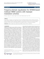
Figure 1 depicts the proposed space-time block coded
DS-CDMA downlink scheme (N× repeats each sample N
times, whereas “S/P” and “P/S” represent a ser ial-to-parallel
and parallel-to-serial conversion, respectively). First, the
original multiuser chip sequence x[n] is constructed:
x[ n]:=
U
u=1
s
u
n/N
c
u
[n]+s
p
n/N
c
p
[n], (1)
where c
u
[n] is the uth user’s code sequence and c
p
[n]is
the pilot code sequence. We assume that both c
u
[n]and
c
p
[n] are normalized and consist of a multiplication of a
user/pilot specific orthogonal Walsh-Hadamard spreading
code of length N and a base-station specific long scrambling
code. Note that the above pilot insertion technique is simi-
lar to the so-called common pilot channel (CPICH) [19]in
forthcoming 3G systems. Second, the original multiuser chip
sequence x[n] is serial-to-parallel converted into the 1 × KN
multiuser chip block sequence x[i]:
x[i]:=
x[ iKN], , x
(i +1)KN − 1
. (2)
Third, the multiuser chip block sequence x[i]istransformed
into the two 1 × KN block sequences x
1
[i]andx
2
[i]:
x
1
[2i] x
1
[2i +1]
x
2
[2i] x
2
[2i +1]
:=
x[2i] −x
∗
[2i +1]P
KN
x[2i +1] x
∗
[2i]P
KN
,
(3)
where P
N
is an N × N permutation matrix that performs a
reversal of the entries, that is, [P
N
]
n,n
= δ[n + n
− N − 1].
Fourth, we add a zero postfix of length L to each block of the
block sequence x
j
[i], resulting into the 1 × (KN + L)block
sequence u
j
[i]: u
j
[i]:= x
j
[i]T,whereT is the KN×(KN+L)
zero postfix insertion matrix: T := [I
KN
, 0
KN×L
]. Finally, the
block sequence u
j
[i] is parallel-to-serial converted into the
space-time block coded multiuser chip sequence u
j
[n]:
u
j
i(KN + L)
, , u
j
(i +1)(KN + L) − 1
:= u
j
[i], (4)
which is transmitted at the jth transmit antenna w ith rate
1/T
c
(the chip rate).
2.2. Channel model
Assuming the mth receive antenna is sampled at the chip rate,
the received sequence at the mth receive antenna can be writ-
ten as
y
m
[n] =
2
j=1
L
l=0
h
m, j
[l]u
j
[n − l]+e
m
[n], (5)
where e
m
[n] is the additive noise at the mth receive antenna
and h
m, j
[l] is the channel from the jth transmit antenna to
the mth receive antenna, including transmit and receive fil-
ters. We assume that h
m, j
[l] is FIR with order L
j,m
and that
L is a known upper bound on max
j,m
{L
j,m
}. Note that L was
also chosen as the zero postfix length in Section 2.1.
2.3. Receiver design
A first option is to ser ial-to-parallel convert the received se-
quence y
m
[n] into the 1 × (KN + L) received block sequence
y
m
[i]:
y
m
[i]:=
y
m
i(KN + L)
, , y
m
(i +1)(KN + L) − 1
,
(6)
then to apply space-time decoding and Viterbi equaliza-
tion as in [18], and finally, to perform simple despread-
ing. This detection technique is overall ML, but leads to a
very large computational complexity. That is why we pur-
sue suboptimal detection by means of space-time chip equal-
ization, which lowers the computational complexity signif-
icantly. Note that this suboptimal detection technique can
also be applied to the STBC technique of [15]onitsown,
without combining it with the original single-antenna DS-
CDMA downlink scheme.
We first introduce some new notation. Defining the M×1
vector
y[n]:=
y
1
[n], , y
M
[n]
T
,(7)
we can write
y[n]
=
2
j=1
L
l=0
h
j
[l]u
j
[n − l]+e[n], (8)
where e[n] is similarly defined as y[n], and
h
j
[l]:=
h
1, j
[l], , h
M, j
[l]
T
. (9)
Space-Time Chip Equalization 743
Further, defining the (Q +1)M × KN matrix
Y[i]
:=
y
i(KN + L)
··· y
i(KN + L)+KN − 1
.
.
.
.
.
.
.
.
.
y
i(KN + L)+Q
··· y
i(KN + L)+KN − 1+Q
,
(10)
we can write
Y[i] =
2
j=1
H
j
U
j
[i]+E[i], (11)
where E[i] is similarly defined as Y[i],
H
j
:=
h
j
[L] ··· h
j
[0] 0
M×1
··· 0
M×1
0
M×1
h
j
[L] ··· h
j
[0] ··· 0
M×1
.
.
.
.
.
.
.
.
.
.
.
.
.
.
.
0
M×1
0
M×1
··· h
j
[L] ··· h
j
[0]
,
U
j
[i]
:=
u
j
i(KN + L) − L
··· u
j
i(KN + L) − L + KN − 1
.
.
.
.
.
.
.
.
.
u
j
i(KN + L)+Q
··· u
j
i(N + L)+Q + KN − 1
.
(12)
The parameter Q basically represents the order of the
adopted space-time chip equalizer. This equalizer order Q is
usually chosen to be close to the channel order L. For the sake
of conciseness, we assume Q = L. However, the proposed re-
sults can easily be extended to other values of the equalizer
order Q.
Choosing Q = L, it is clear from the zero postfix insertion
that U
j
[i] can be expressed as
U
j
[i] = T
x
j
[i]
:=
x
j
[i]J
(−L)
KN
.
.
.
x
j
[i]J
(L)
KN
, (13)
with J
(l)
N
the N × N shift matrix with [J
(l)
N
]
n,n
= δ[ n − n
− l]
(note that J
(0)
N
= I
N
).
To proceed, the straightforward way is to apply two
space-time chip equalizers on Y[i]torecoverx
1
[i]andx
2
[i],
then to apply space-time decoding to recover x[2i]andx[2i+
1], and finally, to perform simple despreading. Since this
comes down to an equalization problem with two sources,
we need three chip rate sampled receive antennas at each mo-
bile station for a finite-length ZF solution to exist (for J>2
transmit antennas, we need J + 1 chip rate sampled receive
antennas at each mobile station). However, we will show that
the space-time chip equalization and space-time decoding
operations can be swapped, which allows us to first apply
space-time decoding on Y[2i]andY[2i + 1], then to apply
two space-time chip equalizers to recover x[2i]andx[2i +1],
and finally, to perform simple despreading. Since this comes
down to two equalization problems with only one source, we
need only two chip rate sampled receive antennas at each mo-
bile station for a finite-length ZF solution to exist (even for
J>2 transmit antennas, we need only two chip rate sampled
receive antennas at each mobile station). The latter option
clearly has more degrees of freedom to tackle the equaliza-
tion problem, and therefore leads to a better performance.
This option is explained in more detail next.
2.3.1. Space-time decoding
Using (11)and(13), we can write Y[2i]andY[2i +1]as
Y[2i]
= H
1
T
x
1
[2i]
+ H
2
T
x
2
[2i]
+ E[2i],
Y[2i +1]= H
1
T
x
1
[2i +1]
+ H
2
T
x
2
[2i +1]
+ E[2i +1].
(14)
Since x
1
[2i +1]=−x
∗
2
[2i]P
KN
(see (3)), we can derive from
(13) that
T
x
1
[2i +1]
=
x
1
[2i +1]J
(−L)
KN
.
.
.
x
1
[2i +1]J
(L)
KN
=−
x
∗
2
[2i]P
KN
J
(−L)
KN
.
.
.
x
∗
2
[2i]P
KN
J
(L)
KN
=−
x
∗
2
[2i]J
(L)
KN
.
.
.
x
∗
2
[2i]J
(−L)
KN
P
KN
=−P
2L+1
x
∗
2
[2i]J
(−L)
KN
x
∗
2
[2i]J
(L)
KN
P
KN
=−P
2L+1
T
∗
x
2
[2i]
P
KN
.
(15)
Similarly, since x
2
[2i +1]= x
∗
1
[2i]P
KN
(see (3)), we can de-
rive from (13) that
T
x
2
[2i +1]
= P
2L+1
T
∗
x
1
[2i]
P
KN
. (16)
Conjugating Y[2i + 1] and multiplying it to the right-hand
side with P
KN
, we then arrive at
Y
∗
[2i +1]P
KN
= H
∗
1
T
∗
x
1
[2i +1]
P
KN
+ H
∗
2
T
∗
x
2
[2i +1]
P
KN
+ E
∗
[2i +1]P
KN
=−H
∗
1
P
2L+1
T
x
2
[2i]
+ H
∗
2
P
2L+1
T
x
1
[2i]
+ E
∗
[2i +1]P
KN
,
(17)
where the second equality is due to (15)and(16). Stacking
Y[2i]andY
∗
[2i +1]P
KN
:
¯
Y[i]:=
Y[2i]
Y
∗
[2i +1]P
KN
, (18)
744 EURASIP Journal on Applied Signal Processing
and using the fact that x
1
[2i] = x[2i]andx
2
[2i] = x[2i +1]
(see (3)), we finally obtain
¯
Y[i] = H
¯
X[i]+
¯
E[i], (19)
where
¯
E[i] is similarly defined as
¯
Y[i],
H :=
H
1
H
2
H
∗
2
P
2L+1
−H
∗
1
P
2L+1
,
¯
X[i]:=
T
x[2i]
T
x[2i +1]
.
(20)
2.3.2. Space-time chip equalization
We now apply two space-time chip equalizers on
¯
Y[i]: f
e
and
f
o
. The 1 × 2(L +1)M space-time chip equalizer f
e
is designed
to extract the even multiuser chip block x[2i], whereas the 1×
2(L +1)M space-time chip equalizer f
o
is designed to extract
the odd multiuser chip block x[2i +1]:
ˆ
x[2i] = f
e
¯
Y[i],
ˆ
x[2i +1]= f
o
¯
Y[i]. (21)
Note that x[2i]andx[2i + 1] are two distinct rows of
¯
X[i].
A first possibility is to apply two ZF space-time chip
equalizers, completely eliminating the interchip interference
(ICI) at the expense of potentially excessive noise enhance-
ment:
f
e
= i
e
H
H
R
−1
e
H
−1
H
H
R
−1
e
,
f
o
= i
o
H
H
R
−1
e
H
−1
H
H
R
−1
e
,
(22)
where i
e
is a 1×(4L+2) unit vector with a one in the (L+1)th
position, i
o
is a 1 × (4L + 2) unit vector with a one in the
(3L + 2)th position, and R
e
:= 1/(KN)E {
¯
E[i]
¯
E
H
[i]}.Asec-
ond possibility is to apply two minimum mean-squared error
(MMSE) space-time chip equalizers, balancing ICI elimina-
tion with noise enhancement:
f
e
= i
e
H
H
R
−1
e
H + R
−1
x
−1
H
H
R
−1
e
,
f
o
= i
o
H
H
R
−1
e
H + R
−1
x
−1
H
H
R
−1
e
,
(23)
where R
x
:= 1/(KN)E {
¯
X[i]
¯
X
H
[i]}.
Assuming the additive noise sequences {e
m
[n]}
M
m=1
are
mutually uncorrelated and white with variance σ
2
e
,wecan
write R
e
= σ
2
e
I
2(L+1)M
. Furthermore, assuming the data
symbol sequences {s
u
[n]}
U
u=1
are mutually uncorrelated and
white with variance σ
2
s
, the original multiuser chip sequence
x[ n] is white with variance σ
2
x
= σ
2
s
J/N (justified by the long
scrambling code), and we c an write R
x
= σ
2
x
diag{[r
x
, r
x
]}=
σ
2
s
J/N diag{[r
x
, r
x
]},wherer
x
= [(KN−L)/(KN), ,(KN−
1)/(KN), 1, (KN − 1)/(KN), ,(KN − L)/(KN)].
2.3.3. Despreading
We define the 1
× KU multiuser data symbol block s[i]as
s[i]:
=
s
1
[i], , s
U
[i]
, (24)
where s
u
[i] is the uth user’s 1 × K data symbol block given by
s
u
[i]:=
s
u
[iK], , s
u
(i +1)K − 1
. (25)
Note that the 1 × K pilot symbol block s
p
[i] is similarly de-
fined as s
u
[i]. We further define the multiuser code matrix
C[i]as
C[i]:=
C
1
[i]
T
, , C
U
[i]
T
T
, (26)
where C
u
[i] is the uth user’s code matrix given by
C
u
[i]:=
c
u
[iK]
.
.
.
c
u
(i +1)K − 1
, (27)
with c
u
[k]:= [c
u
[kN], , c
u
[(k +1)N − 1]]. Note that the
pilot code matrix C
p
[i] is similarly defined as C
u
[i]. It is then
clear from (1) that the multiuser chip block x[i]canbeex-
pressed as
x[i] =
U
u=1
s
u
[i]C
u
[i]+s
p
[i]C
p
[i]
= s[i]C[i]+s
p
[i]C
p
[i].
(28)
Hence, by despreading the multiuser chip block x[i] with the
uth user’s code matrix C
u
[i], we obtain
s
u
[i] = x[i]C
H
u
[i] (29)
because C
p
[i]C
H
u
[i] = 0
K×K
, C
u
[i]C
H
u
[i] = 0
K×K
for u = u
,
and C
u
[i]C
H
u
[i] = I
K
. Therefore, once x[i]hasbeenesti-
mated, we can find an estimate for s
u
[i] by simple despread-
ing:
ˆ
s
u
[i] =
ˆ
x[i]C
H
u
[i]. (30)
Plugging (30) into (21), we thus obtain
ˆ
s
u
[2i] = f
e
¯
Y[i]C
H
u
[2i],
ˆ
s
u
[2i +1]= f
o
¯
Y[i]C
H
u
[2i +1].
(31)
From these equations, it is also clear that the order of equal-
ization and despreading can be reversed. In other words, we
can first despread
¯
Y[i]withC
u
[2i]andC
u
[2i + 1], and then
perform space-time chip equalization on both results.
3. PRACTICAL SPACE-TIME CHIP EQUALIZER DESIGN
In this section, we focus on prac tical space-time chip equal-
izer design. In [20, 21], we have developed two pilot-based
space-time chip equalizer design methods for the origi-
nal single-antenna DS-CDMA downlink scheme: a training-
based method and a semiblind method. In this section, these
two methods are appropriately modified and applied to the
Space-Time Chip Equalization 745
proposed space-time coded DS-CDMA downlink scheme.
We consider a burst of 2I data symbol blocks.
The goal of the training-based method is to compute the
uth user’s even and odd data symbol blocks {s
u
[2i]}
I
i=1
and
{s
u
[2i +1]}
I
i=1
from {
¯
Y[i]}
I
i=1
, based on the even and odd
pilot symbol blocks {s
p
[2i]}
I
i=1
and {s
p
[2i +1]}
I
i=1
, the even
and odd pilot code matrices {C
p
[2i]}
I
i=1
and {C
p
[2i +1]}
I
i=1
,
and the uth user’s even and odd code matrices {C
u
[2i]}
I
i=1
and {C
u
[2i +1]}
I
i=1
.
Thegoalofthesemiblind method is to compute the
uth user’s even and odd data symbol blocks {s
u
[2i]}
I
i=1
and
{s
u
[2i +1]}
I
i=1
from {
¯
Y[i]}
I
i=1
, based on the even and odd
pilot symbol blocks {s
p
[2i]}
I
i=1
and {s
p
[2i +1]}
I
i=1
, the even
and odd pilot code matrices {C
p
[2i]}
I
i=1
and {C
p
[2i +1]}
I
i=1
,
and the even and odd multiuser code matrices {C[2i]}
I
i=1
and
{C[2i +1]}
I
i=1
. Note that the semiblind method requires the
knowledge of the ac tive codes. This knowledge can be ob-
tained by means of a limited feedback from the base station
to the mobile station (only the indices of the active codes
have to be fed back). However, this knowledge can also be ob-
tained by first adopting the training-based method to design
a space-time chip equalizer, and then comparing for each
code the energy obtained after equalization and despreading
with some threshold in order to decide whether this code is
active or not.
For the sake of conciseness, we will only focus on block
implementations. These block implementations might look
rather complex, but they form the basis for practical low-
complexity adaptive implementations, which can be derived
in a similar fashion as done in [20, 21].
For the sake of simplicity, we make the following assump-
tions:
(A1) the matrix H has full column rank 4L +2;
(A2) the matrices
¯
X[2i]and
¯
X[2i +1]havefullrowrank
4L +2foralli
∈{1, , I}.
The first assumption requires that 2(L +1)(M − 1) ≥ 2L,
which means we need only M ≥ 2receiveantennasateach
mobile station (even for J>2 transmit antennas, we need
only M ≥ 2 receive antennas at each mobile station). The
second assumption requires that 4L +2 ≤ KN. Note that
these assumptions are not really necessary for the proposed
methods to work. The only true requirement is that x[2i]and
x[2i + 1] belong to the row space of
¯
Y[i]foralli ∈{1, , I}.
Assumptions (A1) and (A2) are sufficient but not necessary
conditions for this. However, they considerably simplify the
analysis.
Assume no noise is present. Because of assumption (A1),
the row space of
¯
Y[i] equals the row space of
¯
X[i]. Hence,
there exist two 1 × 2(L +1)M space-time chip equalizers f
e
and f
o
,forwhich
f
e
¯
Y[i] − x[2i] = 0
1×KN
,
f
o
¯
Y[i] − x[2i +1]= 0
1×KN
.
(32)
Because of assumption (A2), these two space-time chip
equalizers f
e
and f
o
are ZF. By using (28), we then obtain
f
e
¯
Y[i] − s[2i]C[2i] − s
p
[2i]C
p
[2i] = 0
1×KN
,
f
o
¯
Y[i] − s[2i +1]C[2i +1]− s
p
[2i +1]C
p
[2i +1]= 0
1×KN
.
(33)
3.1. Training-based method
By despreading (33) with the even and o dd pilot code mat ri-
ces C
p
[2i]andC
p
[2i +1],weobtain
f
e
¯
Y[i]C
H
p
[2i] − s
p
[2i] = 0
1×K
,
f
o
¯
Y[i]C
H
p
[2i +1]− s
p
[2i +1]= 0
1×K
(34)
because C[i]C
H
p
[i] = 0
K×K
and C
p
[i]C
H
p
[i] = I
K
.The
training-based method solves (34)forf
e
and f
o
for all i ∈
{1, , I}. In the noisy case, this leads to the following least
squares (LS) problems:
min
f
e
I
i=1
f
e
¯
Y[i]C
H
p
[2i] − s
p
[2i]
2
,
min
f
o
I
i=1
f
o
¯
Y[i]C
H
p
[2i +1]− s
p
[2i +1]
2
,
(35)
which can be interpreted as follows. The space-time de-
coded output matrix
¯
Y[i] is first equalized with the even
and odd space-time chip equalizers f
e
and f
o
, and then de-
spread with the even and odd pilot code matrices C
p
[2i]and
C
p
[2i + 1]. The resulting even and odd vectors f
e
¯
Y[i]C
H
p
[2i]
and f
o
¯
Y[i]C
H
p
[2i + 1] should then be as close as possible in an
LS sense to the even and odd pilot symbol blocks s
p
[2i]and
s
p
[2i +1]foralli ∈{1, , I}. The solutions of (35)canbe
written as
ˆ
f
e
=
I
i=1
s
p
[2i]C
p
[2i]
¯
Y
H
[i]
×
I
i=1
¯
Y[i]C
H
p
[2i]C
p
[2i]
¯
Y
H
[i]
−1
,
ˆ
f
o
=
I
i=1
s
p
[2i +1]C
p
[2i +1]
¯
Y
H
[i]
×
I
i=1
¯
Y[i]C
H
p
[2i +1]C
p
[2i +1]
¯
Y
H
[i]
−1
.
(36)
The obtained space-time chip equalizers
ˆ
f
e
and
ˆ
f
o
are sub-
sequently used to estimate the uth user’s even and odd data
symbol blocks s
u
[2i]ands
u
[2i +1]foralli ∈{1, , I}:
ˆ
s
u
[2i] =
ˆ
f
e
¯
Y[i]C
H
u
[2i],
ˆ
s
u
[2i +1]=
ˆ
f
o
¯
Y[i]C
H
u
[2i +1].
(37)
These soft estimates are fed into a decision device that deter-
mines the nearest constellation point.
746 EURASIP Journal on Applied Signal Processing
3.2. Semiblind method
The semiblind method directly solves (33)for(f
e
, s[2i]) and
(f
o
, s[2i +1]) forall i ∈{1, , I}. In the noisy case, this leads
to the following LS problems:
min
(f
e
,{s[2i]}
I
i=1
)
I
i=1
f
e
¯
Y[i]
− s[2i]C[2i] − s
p
[2i]C
p
[2i]
2
,
min
(f
o
,{s[2i+1]}
I
i=1
)
I
i=1
f
o
¯
Y[i] − s[2i +1]C[2i +1]
− s
p
[2i +1]C
p
[2i +1]
2
.
(38)
Since we are interested in f
e
and f
o
, we can first solve (38)for
s[2i]ands[2i +1]foralli ∈{1, , I}, which results into
ˆ
s[2i] = f
e
¯
Y[i]C
H
[2i],
ˆ
s[2i +1]= f
o
¯
Y[i]C
H
[2i +1]
(39)
because C[i]C
H
p
[i] = 0
K×K
and C
p
[i]C
H
p
[i] = I
K
. Substitut-
ing
ˆ
s[2i]and
ˆ
s[2i +1]in(38) leads to the following LS prob-
lems:
min
f
e
I
i=1
f
e
¯
Y[i]
I
KN
− C
H
[2i]C[2i]
− s
p
[2i]C
p
[2i]
2
,
min
f
o
I
i=1
f
o
¯
Y[i]
I
KN
− C
H
[2i +1]C[2i +1]
− s
p
[2i +1]C
p
[2i +1]
2
,
(40)
which can be interpreted as follows. The space-time decoded
output matrix
¯
Y[i] is first equalized with the even and o dd
space-time chip equalizers f
e
and f
o
and then projected on the
orthogonal complement of the subspace spanned by the even
and odd multiuser code matrices C[2i]andC[2i +1].The
resulting even and odd vectors f
e
¯
Y[i](I
KN
−C
H
[2i]C[2i]) and
f
o
¯
Y[i](I
KN
− C
H
[2i +1]C[2i + 1]) should then be as close as
possible in an LS sense to the even and odd pilot chip blocks
s
p
[2i]C
p
[2i]ands
p
[2i +1]C
p
[2i +1]foralli ∈{1, , I}.
The solutions of (40)canbewrittenas
ˆ
f
e
=
I
i=1
s
p
[2i]C
p
[2i]
¯
Y
H
[i]
×
I
i=1
¯
Y[i]
I
KN
− C
H
[2i]C[2i]
¯
Y
H
[i]
−1
,
ˆ
f
o
=
I
i=1
s
p
[2i +1]C
p
[2i +1]
¯
Y
H
[i]
×
I
i=1
¯
Y[i]
I
KN
− C
H
[2i +1]C[2i +1]
¯
Y
H
[i]
−1
.
(41)
The obtained space-time chip equalizers
ˆ
f
e
and
ˆ
f
o
are sub-
sequently used to estimate the uth user’s even and odd data
symbol blocks s
u
[2i]ands
u
[2i +1]foralli ∈{1, , I}:
ˆ
s
u
[2i] =
ˆ
f
e
¯
Y[i]C
H
u
[2i],
ˆ
s
u
[2i +1]=
ˆ
f
o
¯
Y[i]C
H
u
[2i +1].
(42)
These soft estimates are fed into a decision device that deter-
mines the nearest constellation point.
With some algebraic manipulations, it is easy to prove
that (40)isequivalentto
min
f
e
I
i=1
f
e
¯
Y[i]C
H
p
[2i] − s
p
[2i]
2
+
f
e
¯
Y[i]
I
KN
−C
H
[2i]C[2i] − C
H
p
[2i]C
p
[2i]
2
,
min
f
o
I
i=1
f
o
¯
Y[i]C
H
p
[2i +1]− s
p
[2i +1]
2
+
f
o
¯
Y[i]
I
KN
− C
H
[2i +1]C[2i +1]
− C
H
p
[2i +1]C
p
[2i +1]
2
.
(43)
This shows that (40) naturally decouples into a training-
based part and a blind part (hence the name semiblind). The
training-based part corresponds to (35). The blind part can
be interpreted as follows. The space-time decoded output
matrix
¯
Y[i] is first equalized with the even and odd space-
time chip equalizers f
e
and f
o
and then projected on the or-
thogonal complement of the subspace spanned by the even
and odd multiuser code matrices C[2i]andC[2i+ 1] and the
even and odd pilot code matrices C
p
[2i]andC
p
[2i +1].The
resulting even and odd vectors f
e
¯
Y[i](I
KN
− C
H
[2i]C[2i] −
C
H
p
[2i]C
p
[2i]) and f
o
¯
Y[i](I
KN
−C
H
[2i+1]C[2i+1]−C
H
p
[2i+
1]C
p
[2i + 1]) should then be as small as possible in an LS
sense for all i ∈{1, , I}. Note that when the user load in-
creases, the orthogonal complement of the subspace spanned
by the even and odd multiuser code matrices C[2i]and
C[2i + 1] and the even and odd pilot code matrices C
p
[2i]
and C
p
[2i + 1] decreases in dimension. As a result, the in-
formation that the blind part contributes to the training-
based part diminishes, and the semiblind method converges
to the training-based method. In the extreme case when the
system is fully loaded, that is, N = U − 1, the orthogonal
complement of the subspace spanned by the even and odd
multiuser code matrices C[2i]andC[2i + 1] and the even
and odd pilot code matrices C
p
[2i]andC
p
[2i +1]isempty,
that is, I
KN
− C
H
[2i]C[2i] − C
H
p
[2i]C
p
[2i] = 0
KN×KN
and
I
KN
− C
H
[2i +1]C[2i +1]− C
H
p
[2i +1]C
p
[2i +1]= 0
KN×KN
.
Hence, the blind part does not contribute any additional
information to the training-based part, and the semiblind
method reduces to the training based method, that is, (43)
reduces to (35).
Space-Time Chip Equalization 747
4. SIMULATION RESULTS
In this section, we compare the proposed space-time chip
equalizer for the proposed space-time coded downlink
CDMA t ransmission scheme with the space-time RAKE re-
ceiver for the space-time spreading scheme, which encom-
passes the space-time coded downlink CDMA transmission
schemes that have been proposed for the UMTS and IS-2000
W-CDMA standards [16]. We do not consider channel codes
when comparing the above transceivers. Otherwise, it will
not be very clear whether a performance gain is due to the
transceiver or the channel code. Moreover, the influence of
channel codes on performance has been studied extensively
in literature. In W-CDMA, the target coded BER typically is
10
−6
, which boils down to an uncoded BER of 10
−2
with a
convolutional code of rate 1/2, constraint length 7, and soft
decision Viterbi [22]. Therefore, we compare the different
transceivers at an uncoded BER of 10
−2
in the sequel.
We consider a downlink CDMA system with a spreading
factor of N = 32, J = 2 transmit antennas at the base station,
and M = 2 receive antennas at each mobile station. We as-
sume that all channels are independent. We further assume
that each channel h
j,m
[n] is FIR with order L
j,m
= 3and
has independent Rayleigh fading channel taps of equal vari-
ance σ
2
h
. Note that the bandwidth efficiency of the proposed
space-time coded downlink CDMA transmission scheme is
1
= KU/(KN + L), whereas the bandwidth efficiency of
the space-time spreading scheme is
2
= U/N.Hence,in
order to make a fair comparison between the two systems,
their spectral efficiencies should be comparable. We therefore
take K = 5andL = 3 for the proposed space-time coded
downlink CDMA transmission scheme, which results into
1
/
2
≈ 0.98. We assume QPSK modulated data symbols,
and define the signal-to-noise ratio (SNR) as the received bit
energy over the noise power:
SNR
=
σ
2
s
/2
2
j=1
L
l=0
E
h
j
[l]
2
σ
2
e
=
2(L +1)σ
2
s
σ
2
h
σ
2
e
.
(44)
Two test cases are investigated.
Test case 1
We first assume that the pilot enables us to obtain perfect
channel knowledge at the receiver. We then compare the pro-
posed MMSE space-time chip equalizer for the proposed
space-time coded downlink CDMA transmission scheme
with the MMSE space-time RAKE receiver for the space-
time spreading scheme (see [23, 24]), which is different from
the matched space-time RAKE receiver for the space-time
spreading scheme (see [16]) because it uses an MMSE filter
instead of a matched filter to combine the finger outputs. It
has been shown in [23, 24] that for the space-time spreading
scheme, the MMSE space-time RAKE receiver significantly
outperforms the matched space-time RAKE receiver. Figures
2, 3,and4 compare the performance of the two transceivers
20151050
SNR (dB)
10
−4
10
−3
10
−2
10
−1
10
0
10
1
BER
Proposed transceiver
Existing transceiver
ML bound
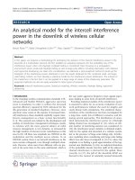
Figure 2: Performance comparison for U = 1.
20151050
SNR (dB)
10
−4
10
−3
10
−2
10
−1
10
0
10
1
BER
Proposed transceiver
Existing transceiver
ML bound
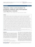
Figure 3: Performance comparison for U = 15.
for U = 1, U = 15, and U = 31 users, respectively. The
performance results are averaged over 1000 random chan-
nel realizations, where for each channel realization, we con-
sider 10 random data and noise realizations corresponding
to I = 10 (100 data symbols per user). Also shown is the the-
oretical performance of
j,m
(L
j,m
+1) = 16-fold diversity
over Rayleigh fading channels [22].
First of all, we see that the proposed transceiver comes
close to extracting the maximum diversity at low-to-medium
748 EURASIP Journal on Applied Signal Processing
20151050
SNR (dB)
10
−4
10
−3
10
−2
10
−1
10
0
10
1
BER
Proposed transceiver
Existing transceiver
ML bound
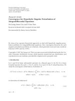
Figure 4: Performance comparison for U = 31.
user loads. More specifically, at a BER of 10
−2
, the proposed
transceiver incurs a 0.1, 1, and 1.8 dB loss compared to the
theoretical ML bound for U = 1, U = 15, and U = 31 users,
respectively. The existing transceiver, on the other hand, per-
forms poorly at medium-to-high user loads. At a BER of
10
−2
, it incurs a 0.5, 3, and 8.2 dB performance loss com-
pared to the proposed transceiver for U = 1, U = 15, and
U = 31 users, respectively. The existing tr ansceiver is not ca-
pable of completely suppressing the MUI at high SNR. This
results into a flooring of the BER at high SNR. Note that the
flooring level increases with the number of users U.
Test case 2
We now investigate the performance of the pilot-based meth-
ods. Note that for the space-time spreading scheme, it is easy
to derive a training-based method to estimate the combining
filter of the space-time RAKE receiver based on the knowl-
edge of the pilot. The performance results are again averaged
over 1000 random channel realizations, where for each chan-
nel realization, we consider 10 random data and noise re-
alizations corresponding to I = 10 (100 data symbols per
user). Figures 5, 6,and7 compare the performance of the
different methods for U = 1, U = 15, and U = 31 users,
respectively.
First of all, we observe that the difference between
the training-based method and the semiblind method for
the proposed transceiver decreases with an increasing user
load, as indicated in Section 3.2. Next, we observe that the
training-based method for the existing transceiver performs
much worse than the training-based and semiblind meth-
ods for the proposed transceiver at medium-to-high user
loads. Finally, note that for the proposed transceiver, the
MMSE performance discussed in test case 1 can be viewed
20151050
SNR (dB)
10
−4
10
−3
10
−2
10
−1
10
0
10
1
BER
Proposed transceiver: training-based
Proposed transceiver: semiblind
Existing transceiver: training-based
Figure 5: Performance of pilot-based methods for U = 1.
20151050
SNR (dB)
10
−4
10
−3
10
−2
10
−1
10
0
10
1
BER
Proposed transceiver: training-based
Proposed transceiver: semiblind
Existing transceiver: training-based
Figure 6: Performance of pilot-based methods for U = 15.
as the convergence point of the training-based and semi-
blind methods as I goes to infinity. Comparing the fig-
ures of test case 2 with the figures of test case 1, we ob-
serve that for I = 10, the training-based method is still
far from the MMSE performance, whereas the semiblind
method is already very close to the MMSE performance.
Hence, as I increases, the semiblind method converges
faster to the MMSE performance than the training-based
method.
Space-Time Chip Equalization 749
20151050
SNR (dB)
10
−4
10
−3
10
−2
10
−1
10
0
10
1
BER
Proposed transceiver: training-based
Proposed transceiver: semiblind
Existing transceiver: training-based
Figure 7: Performance of pilot-based methods for U = 31.
5. CONCLUSIONS
We have aimed at combining STBC techniques with the orig-
inal single-antenna DS-CDMA downlink scheme, resulting
into the so-called space-time block coded DS-CDMA down-
link schemes. Many space-time block coded DS-CDMA
downlink transmission schemes can be considered. We have
focussed on a new scheme that enables both the maxi-
mum multiantenna diversity and the maximum multipath
diversity. Although this maximum diversity can only be col-
lected by ML detection, we have pursued suboptimal detec-
tion by means of space-time chip equalization, which low-
ers the computational complexity significantly. To design the
space-time chip equalizers, we have also proposed efficient
pilot-based methods. Simulation results have shown im-
proved per formance over the space-time RAKE receiver for
the space-time block coded DS-CDMA downlink schemes
that have been proposed for the UMTS and IS-2000 W-
CDMA standards.
ACKNOWLEDGMENTS
This research work was carried out in the frame of the Bel-
gian State’s Interuniversity Poles of Attraction Programme
(2002–2007): IAP P5/22 (“Dynamical Systems and Control:
Computation, Identification, and Modelling”) and P5/11
(“Mobile Multimedia Communication Systems and Net-
works”); the Concerted Research Action GOA-MEFISTO-
666 (Mathematical Engineering for Information and Com-
munication Systems Technology) of the Flemish Govern-
ment; and Research Project FWO no. G.0196.02 (“Design
of Efficient Communication Techniques for Wireless Time-
Dispersive Multiuser MIMO Systems”). Part of this work ap-
peared in the proceedings of the International Conference on
Communications (ICC), New York city, NY, April-May 2002.
During this research work, Geert Leus was a Postdoctoral Fel-
low of the Fund for Scientific Research - Flanders (FWO -
Vlaanderen), and Frederik Petr
´
e was a Research Assistant of
the Institute for the Promotion of Innovation by Science and
Technology in Flanders (IWT).
REFERENCES
[1] A. Klein, “Data detection algorithms specially designed for
the downlink of CDMA mobile radio systems,” in Proc. IEEE
Vehicular Technology Conference, vol. 1, pp. 203–207, Phoenix,
Ariz, USA, May 1997.
[2] I. Ghauri and D. Slock, “Linear receivers for the DS-CDMA
downlink exploiting orthogonality of spreading sequences,”
in Proc. 32nd Asilomar Conf. on Signals, Systems, and Comput-
ers, vol. 1, pp. 650–654, Pacific Grove, Calif, USA, November
1998.
[3] T. P. Krauss, W. J. Hillery, and M. D. Zoltowski, “Downlink
specific linear equalization for frequency selective CDMA cel-
lular systems,” Journal of VLSI Signal Processing, vol. 30, no. 3,
pp. 143–161, 2002.
[4] C. D. Frank, E. Visotsky, and U. Madhow, “Adaptive inter-
ference suppression for the downlink of a direct sequence
CDMA system with long spreading sequences,” Journal of
VLSI Signal Processing, vol. 30, no. 1–3, pp. 273–291, 2002.
[5] G. J. Foschini and M. J. Gans, “On limits of wireless commu-
nications in a fading environment when using multiple an-
tennas,” Wireless Personal Communications,vol.6,no.3,pp.
311–335, 1998.
[6] G.G.RaleighandJ.M.Cioffi, “Spatio-temporal coding for
wireless communications,” IEEE Trans. Communications, vol.
46, no. 3, pp. 357–366, 1998.
[7] D. Gesbert, H. Bolcskei, D. Gore, and A. Paulraj, “MIMO
wireless channels: capacity and performance prediction,” in
IEEE Global Telecommunications Conference, 2000, vol. 2, pp.
1083–1088, San Francisco, Calif, USA, December 2000.
[8] A. Paulraj and T. Kailath, “Increasing capacity in wireless
broadcast systems using distributed transmission/directional
reception (DTDR),” U.S. Patent 5345599, Stanford University,
Stanford, Calif, USA, September 1994.
[9] G. J. Foschini, “Layered space-time architecture for wireless
communication in a fading environment when using multiple
antennas,” Bell Labs Technical Journal, vol. 1, no. 2, pp. 41–59,
1996.
[10] V. Tarokh, N. Seshadri, and A. R. Calderbank, “Space-time
codes for high data rate wireless communication: perfor-
mance criterion and code construction,” IEEE Transactions
on Information Theory, vol. 44, no. 2, pp. 744–765, 1998.
[11] S. M. Alamouti, “A simple tra nsmit diversity technique for
wireless communications,” IEEE Journal on Selected Areas in
Communications, vol. 16, no. 8, pp. 1451–1458, 1998.
[12] V. Tarokh, H. Jafarkhani, and A. R. Calderbank, “Space-time
block codes from orthogonal designs,” IEEE Transactions on
Information Theory, vol. 45, no. 5, pp. 1456–1467, 1999.
[13] Lindskog E. and A. Paulraj, “A transmit diversity scheme for
channels with intersymbol interference,” in Proc. IEEE Con-
ference on International Communications, vol. 1, pp. 307–311,
New Orleans, La, USA, June 2000.
[14] N. Al-Dhahir, “Single-carrier frequency-domain equalization
for space-time block-coded transmissions over frequency-
selective fading channels,” IEEE Communications Letters, vol.
5, no. 7, pp. 304–306, 2001.
750 EURASIP Journal on Applied Signal Processing
[15] S. Zhou and G. B. Giannakis, “Space-time coding with max-
imum diversity gains over frequency-selective fading chan-
nels,” IEEE Signal Processing Letters, vol. 8, no. 10, pp. 269–
272, 2001.
[16] B. Hochwald, T. L. Marzetta, and C. B. Papadias, “A trans-
mitter diversity scheme for wideband CDMA systems based
on space-time spreading,” IEEE Journal on Selected Areas in
Communications, vol. 19, no. 1, pp. 48–60, 2001.
[17] S. Barbarossa, G. Scutari, and A. Swami, “MUI-free CDMA
systems incorporating space-time coding and channel short-
ening,” in Proc. IEEE Int. Conf. Acoustics, Speech, Signal Pro-
cessing, pp. 2213–2216, Orlando, Fla, USA, May 2002.
[18] S. Zhou and G. B. Giannakis, “Single-carrier space-time block
coded transmissions over frequency-selective fading chan-
nels,” IEEE Transactions on Information Theory, vol. 49, no.
1, pp. 164–179, 2003.
[19] H. Holma and A. Toskala, Eds., WCDMA for UMTS: Radio
Access for Third Generation Mobile Communications,JohnWi-
ley & Sons, New York, NY, USA, 2001.
[20] F. Petr
´
e, G. Leus, M. Engels, M. Moonen, and H. De Man,
“Space-time chip equalization for WCDMA forward link with
code-multiplexed pilot and soft handover,” in IEEE Global
Telecommunications Conference, 2001, vol. 1, pp. 280–284, San
Antonio, Tex, USA, November 2001.
[21] F. Petr
´
e, G. Leus, L. Deneire, M. Engels, and M. Moonen,
“Adaptive space-time chip-level equalization for WCDMA
downlink with code-multiplexed pilot and soft handover,” in
Proc. IEEE Conference on International Communications,pp.
1635–1639, New York City, NY, USA, April 2002.
[22] J. G. Proakis, Digital Communications, McGraw-Hill, New
York, NY, USA, 3rd edition, 1995.
[23] M. Lenardi, A. Medles, and D. T. M. Slock, “Comparison
of downlink transmit diversity schemes for RAKE and SINR
maximizing receivers,” in Proc. IEEE Conference on Inter-
national Communications, pp. 1679–1683, New Orleans, La,
USA, June 2001.
[24] C. D. Frank, “MMSE reception of DS-CDMA with open-loop
transmit diversity,” in Proc. 2nd International Conference on
3G Mobile Communication Technologies, 2001, pp. 156–160,
London, UK, March 2001.
Geert Leus wasborninLeuven,Belgium,in
1973. He received his Electrical Engineering
degree and the Ph.D. degree in applied sci-
ences from the Katholieke Universiteit Leu-
ven, Belgium, in June 1996 and May 2000,
respectively. He has been a Research Assis-
tant and a Postdoctoral Fellow of the Fund
for Scientific Research - Flanders, Belgium,
from October 1996 till September 2003.
During that per iod, Geert Leus was affili-
ated with the Electrical Engineering Department, the Katholieke
Universiteit Leuven, Belgium. Currently, Geert Leus is an Assis-
tant Professor at the Faculty of Electrical Engineering, Mathemat-
ics, and Computer Science, Delft University of Technology, The
Netherlands. During the summer of 1998, he visited Stanford Uni-
versity, and from March 2001 till May 2002, he was a Visiting Re-
searcher and Lecturer at the University of Minnesota. His research
interests are in the area of signal processing for communications.
Geert Leus received a 2002 IEEE Signal Processing Society Young
Author Best Paper Award. He is a member of the IEEE Signal Pro-
cessing for Communications Technical Committee, and an Asso-
ciate Editor for the IEEE Transactions on Wireless Communica-
tions and the IEEE Signal Processing Letters.
Frederik P etr
´
e was born in Tienen, Bel-
gium, 1974. He received the Electrical En-
gineering degree and the Ph.D. in Applied
Sciences from the Katholieke Universiteit
Leuven, Leuven, Belgium, in July 1997 and
December 2003, respectively. In September
1997, he joined the Design Technolog y for
Integrated Information and Communica-
tion Systems (DESICS) division, Interuni-
versity Micro-Electronics Center (IMEC),
Leuven, Belgium. Within the Digital Broadband Terminals
(DBATE) group of DESICS, he first performed predoctoral re-
search on wireline transceiver design for twisted pair, coaxial ca-
ble, and powerline communications. During the fall of 1998, he
visited the Information Systems Laboratory (ISL), Stanford Univer-
sity, California, USA, working on OFDM-based powerline commu-
nications. In January 1999, he joined the Wireless Systems ( WISE)
group of DESICS as a Ph.D. Researcher, funded by the Institute for
Scientific and Technological Research in Flanders (IWT). Since Jan-
uary 2004, he is a S enior Scientist within the Wireless Research
group of DESICS. He is investigating the baseband signal pro-
cessing algorithms and architectures for future wireless communi-
cation systems, like third generation (3G) and fourth generation
(4G) cellular networks, and wireless local area networks ( WLANs).
His main research interests are modulation theory, multiple ac-
cess schemes, channel estimation and equalization, smart antenna,
and MIMO techniques. He is a member of the ProRISC technical
program committee and the IEEE Benelux Section on Communi-
cations and Vehicular Technology (CVT). He is a member of the
Executive Board and Project Leader of the Reconfigurable Radio
project of the Network of Excellence in Wireless Communications
(NEWCOM), established under the sixth framework of the Euro-
pean Commission.
Marc Moonen received the Electrical Engi-
neering degree and the Ph.D. degree in ap-
plied sciences from the Katholieke Univer-
siteit Leuven, Leuven, Belgium, in 1986 and
1990, respectively. Since 2000, he has been
an Associate Professor at the Electrical En-
gineering Department, Katholieke Univer-
siteit Leuven, where he is currently head-
ing a research team of sixteen Ph.D. candi-
dates and postdocs working in the area of
signal processing for digital communications, wireless communi-
cations, DSL, and audio signal processing. He received the 1994
KU Leuven Research Council Award, the 1997 Alcatel Bell (Bel-
gium) Award (with Piet Vandaele), and was a 1997 “Laureate of the
Belgium Royal Academy of Science.” He was the Chairman of the
IEEE Benelux Signal Processing Chapter (1998–2002), and is cur-
rently a EURASIP AdCom Member (European Association for Sig-
nal, Speech, and Image Processing, 2000). He is the Editor-in-Chief
for the EURASIP Journal on Applied Signal Processing (2003), and
a member of the editorial board of Integration, the VLSI Journal,
IEEE Transactions on Circuits and Systems II, and IEEE Signal Pro-
cessing Magazine.