Báo cáo hóa học: " Design and Implementation of MC-CDMA Systems for Future Wireless Networks" doc
Bạn đang xem bản rút gọn của tài liệu. Xem và tải ngay bản đầy đủ của tài liệu tại đây (1.17 MB, 12 trang )
EURASIP Journal on Applied Signal Processing 2004:10, 1604–1615
c
2004 Hindawi Publishing Corporation
Design and Implementation of MC-CDMA
Systems for Future Wireless Networks
S
´
ebastien Le Nours
CNRS UMR IETR (Institut en Electronique et T
´
el
´
ecommunications de Rennes), INSA Rennes,
20 avenue des Buttes de Co
¨
esmes, 35043 Rennes Cedex, France
Email:
Fabienne Nouvel
CNRS UMR IETR (Institut en Electronique et T
´
el
´
ecommunications de Rennes), INSA Rennes,
20 avenue des Buttes de Co
¨
esmes, 35043 Rennes Cedex, France
Email:
Jean-Franc¸ois H
´
elard
CNRS UMR IETR (Institut en Electronique et T
´
el
´
ecommunications de Rennes), INSA Rennes,
20 avenue des Buttes de Co
¨
esmes, 35043 Rennes Cedex, France
Email:
Received 28 Februar y 2003; Revised 8 October 2003
The emerging need for high data rate wireless services has raised considerable interest in MC-CDMA systems. In this work,
we describe an MC-CDMA system design process for indoor propagation scenarios. The system specifications and simulations
are firstly given, and then implementation aspects on a mixed, multi-DSP and FPGA architecture are presented. In order to
reduce development cycle, we propose the use of efficient design methodologies to improve development steps such as complexity
evaluation, system distribution according to the architecture, and hardware-software code generation. Implementation results of
the considered MC-CDMA system are then given.
Keywords and phrases: MC-CDMA, multi-DSP-FPGA architecture, codesign methodology, hardware-software distribution.
1. INTRODUCTION
The European third-generation (3G) terrestrial mobile sys-
tem under deployment aims at offering a large variety of cir-
cuit and packet services and greater capacity compared to
second-generation (2G) systems. The evolution from 2G to
3G corresponds to adapting a new air interface but most of all
to a change of focus from voice to multimedia. Fourth gener-
ation (4G), as for it, will be defined by the ability to integrate
heterogeneous networks, especially radio mobile networks
and wireless local area networks (WLAN), that is, to offer ac-
cess to all services, all the time and everywhere [1]. Besides,
the rapid growth of Internet services and the increasing inter-
est in portable computing devices are likely to create a strong
demand for high-speed wireless data services. Presumably, it
is anticipated that systems with a maximum information bit
rate of more than 2–20 Mbps in a vehicular environment and
possibly 50–100 Mbps in indoor to pedestrian environments
will be needed, using a 50–100 MHz bandwidth. Key issues
to fully meet these evolution perspectives are based upon the
most efficient use of scarce spectrum resources, and upon the
advent of reconfigurable radio conceivable due to the emer-
gence of software defined radio (SDR) equipments [2].
On the one hand, the multicarrier code-division
multiple-access (MC-CDMA) modulation scheme has al-
ready proven to be a strong candidate as an access tech-
nique for broadband cellular systems [3]. Different concepts
based on the combination of multicarrier (MC) modula-
tion with direct-sequence CDMA (DS-CDMA) have been
introduced in 1993 [4, 5, 6, 7]. Since that time, owing to
its high sp ectral efficiency and high flexibility, MC-CDMA
scheme has become a promising access technique for 4G air
interface. MC-CDMA benefits are for example highlighted
in [8]; it is demonstrated that, with respect to universal mo-
bile telecommunications system (UMTS) and International
Mobile Telecommunications 2000 (IMT2000) requirements
based on a 5 MHz bandwidth channel, a net bit rate up to
4Mbpswith a1/2 rate channel code and even 6 Mbps with
a3/4 rate code could be assigned to a single user for in-
door but also macrocellular environments with a vehicular
Future Design and Implementation of MC-CDMA Systems 1605
mobility. Thus, MC-CDMA is nowadays considered as a very
promising technique, specifically for the downlink of the fu-
ture cellular mobile radio systems. Then, MC-CDMA is for
example studied within the European IST project MATRICE
(MC-CDMA transmission techniques for integrated broad-
band cellular Systems)
1
. This work has been partly carried
out within this project MATRICE which aims at defining a
new air interface for 4G systems.
On the other hand, the advent of such wireless commu-
nication systems also depends on the use of optimized em-
bedded architectures and consequently of advanced design
methods. Due to increased complexity applications, achiev-
ing high performances solutions is no more guaranteed by
fully software (SW) implementation, using general-purpose
processors (GPP) or digital signal processors (DSP), or fully
hardware (HW) implementation on application specific in-
tegrated circuits (ASIC). Thus, heterogeneous architectures
based on the combined use of reconfigurable HW compo-
nents as field programmable gate array (FPGA) and repro-
grammable SW processors such as DSP represent attrac-
tive and appropriate solutions for complex radiocommuni-
cation systems implementation and rapid prototyping. As a
result, concurrent design, or codesign, methods become con-
venient to favour reduced development cycle for SDR system
design [9]. These methods notably make possible efficient
design spaces exploration to achieve an optimized match-
ing between developed algorithms and targeted architectures
[10].
In this context, an implementation of an airport data link
based on MC communications was proposed in [11]. Be-
sides, special focus on equalisation receiver desig n [12]or
system consumption [13] can also be found. In a general way,
this work aims at investigating MC-CDMA system design in
the 4G context, from system definition to implementation
under real-time constraints. This paper is dedicated to the
study of MC-CDMA for indoor propagation scenarios. This
first step is necessary to guarantee the feasibility of the imple-
mentation under real-time constraints. According to channel
properties, different configurations for a MC-CDMA down-
link air interface are proposed and simulated.
Implementation results on a heterogeneous platform
combining DSP and FPGA are also presented. Our imple-
mentation approach is based on specific codesign methods
in order to propose an efficient design flow integrating sys-
tem modelisation, algorithms complexity evaluation, archi-
tectural exploration, automatic code generation, and imple-
mentation on the testbed platform.
This paper is organized as follows. In Section 2,firstof
all, the main features of the studied MC-CDMA system are
presented. Furthermore, used heterogeneous platform is de-
scribed, and the benefits of our codesign approach will be
highlighted. In Section 3, system parameters are presented
and simulation results are given. Section 4 dealswithcom-
plexity analysis of studied MC-CDMA functions, whereas
Section 5 presents implementation aspects of our codesign
1
www.ist-matrice.org
Simulation
and
validation
according to
system
constraints
Implementation on
heterogeneous target
HW
synthesis
HW-SW
interface
synthesis
SW
synthesis
Complexity analysis,
distribution, and
performances prediction
Architecture
definition
System modelisation
System specifications
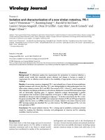
Figure 1: Generic codesign flow.
approach on the mixed architecture. Finally, Section 6 sum-
marizes the results and conclusions are given.
2. MC-CDMA SYSTEM DESIGN
codesign flow enables a top-down design from a system mod-
elisation step to implementation on a prototyping board un-
der real-time constraints, as illustrated in Figure 1. The first
step aims at establishing MC-CDMA system specifications
according to channel properties. Once validated, the system
modelisation will then be used as an entry point in the ar-
chitectural design. This important step deals with HW-SW
distribution according to the specified functions complexity
and the available architecture. Accurate modelisation is re-
quired to efficiently investigate various implementation solu-
tions according to real-time constraints, such as throughput
and consumption. Then, automatic synthesis of the adopted
solution, both for the SW part, the HW part, and the inter-
faces, leads to a reduced development time and reliable solu-
tion.
2.1. MC-CDMA system modelisation
The MC-CDMA air interface allows high-capacity networks
and robustness in the case of frequency-selective channels,
taking benefits from CDMA capability offered by the spread
spectrum technique, and MC modulation as orthogonal
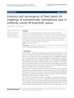
frequency division multiplex (OFDM). A possible generic
downlink transmission scheme is depicted in Figure 2.
Each user data can be simultaneously processed at the
spreading step before MC modulation. In the following,
due to their good properties for the downlink [14], Walsh-
Hadamard (WH) spreading sequences will be considered.
The presented MC-CDMA configuration is based on the
transmission of multiple data per MC-CDMA symbol for
each user. Data d
i
j
(n) denotes the ith, 1 ≤ i ≤ N
b
,datatrans-
mitted by user j,1≤ j ≤ N
u
, in the nth MC-CDMA symbol.
1606 EURASIP Journal on Applied Signal Processing
Channel
estimation
···
.
.
.
Numerical and
BB conversions
.
.
.
OFDM
demodulation
.
.
.
Frequency deinterleaving
.
.
.
.
.
.
.
.
.
.
.
.
Equalisation
.
.
.
Despreading
.
.
.
d
N
b
j
d
1
j
Receiver user j
Propagation
channel model
IF and analog
RF conversions
.
.
.
OFDM
modulation
.
.
.
Frequency interleaving
.
.
.
.
.
.
Spreading
.
.
.
Spreading
.
.
.
.
.
.
d
N
b
N
u
d
N
b
1
d
1
N
u
d
1
1
Last set of
transmitted symbols
foreachactiveuser
First set of
transmitted symbols
foreachactiveuser
MC-CDMA transmitter
Figure 2: Studied MC-CDMA transmitter and receiver.
The maximum number of available users, which is also equal
to the length of the WH spreading sequences, will be denoted
N
u
. The total number of subcarriers is N
c
= N
z
+ N
cu
,where
N
z
and N
cu
are the number of unused and used subcarriers,
respectively. Therefore, the number of data transmitted by
each user in one MC-CDMA symbol is N
b
= N
cu
/N
u
.Fre-
quency interleaving is performed in order to fully exploit the
frequency diversity offered by OFDM modulation.
At the receiver part, despreading is done according to
the specific user sequence after equalisation in the frequency
domain. The system synchronisation and intermediate fre-
quency (IF) and baseband (BB) conversions problems are
beyond the scope of this paper and will not be addressed.
Among various equalisation techniques, we especially fo-
cus on single-user detection techniques. Channel estimation
function can efficiently be performed by using pilot subcar-
riers insertion. The arrangement of these pilots must guar-
antee an optimum sampling of the channel transfer function
in time and in frequency, depending on the bandwidth co-
herence and on the time coherence of the channel [15].
Obviously, MC-CDMA system offers high flexibility in
resources (spectral efficiency, number of users) allocation
which consequently induces large design spaces. As a result,
high-level design methods are convenient in order to deal
with such complexity and for efficient implementation.
2.2. Description of the proposed codesign approach
Most of radiocommunication systems designed on heteroge-
neous platforms are faced by the complexity of mixing SW
and HW design flows. Functions distribution according to
HW or SW mostly depends on designers experience. Besides,
the matching between algorithm and architecture and es-
timation performances for multicomponent architecture is
rarely addressed.
Thus, as illust rated in similar works [16, 17], a high-
level specification is required to improve HW-SW distribu-
tion and combined s imulation. Our purpose is to propose an
efficient top-down design flow, making possible efficient ar-
chitectural choices taking into account specified algorithms
and heterogeneous target properties. Besides, in order to
favour reusability and to reduce design process duration, a
multisource integration, as well as HW description language
(HDL) sources such as C codes, is required. As illustrated in
Figure 3, our design process is based on the concurrent use of
two codesign methods and their associated tools: the code-
sign methodology for embedded systems (CoMES) method-
ology [18], and the algorithm architecture adequation [19]
(AAA) methodology; “Adequation” is a French word mean-
ing an efficient matching. The first method is used for system
modelisation and simulation, algorithms complexity evalua-
tion, and architectural design, whereas the second one is used
for functions distribution and code generation.
CoMES modelisation combines a graph model with
C-coded algorithms, allowing complete system simulation
without any assumption on architecture. Functions activ-
ity and complexity can then be evaluated using a profiling
step. In a second part, the target architecture can be defined
as a set of interconnected HW and SW processors. Finally,
functions distribution on the multicomponent architecture
can be studied according to system attributes such as time
Future Design and Implementation of MC-CDMA Systems 1607
System validation on
the prototyping board
FPGA
implementation
DSP
implementation
AAA design flow
HW
synthesis
HW-SW
interface
synthesis
SW
synthesis
Implementation
performances evaluations
of the optimised
distributed solution
Automatic functions
distribution and scheduling
AAA specifications
Feedback for
distribution
optimisation
CoMES design flow
System simulation with
architecture limitations
and implementation
performances evaluations
System simulation without
architectural assumptions
Complexity analysis,
and implementation
performances prediction
Architectural
attributes
System modelisation
System specifications
Figure 3: Considered design flow.
IP interfaces
Processing units
Physical links
PCI bus
Slow-port
interface
Quick-port
interface
Peripherals
C6701 CPU
C6701
External
memory banks
Software module
Slow-port
interface
Quick-port
interface
Slow-port
interface
Peripherals
C6701 CPU
C6701
External
memory banks
Software module
Slow-port
interface
Quick-port
interface
Hardware functions
implementation
Memory
controller
Virtex
Hardware
module
External
memory banks
Figure 4: Heterogeneous architecture description.
execution on each component, data communication dura-
tions, and intercomponent interfaces behaviour. At this step,
we can obtain a fully validated and detailed performances
estimation of the mapped functions on the distributed ar-
chitecture. The AAA methodology, as for it, is firstly used
for functions automatic distribution, taking into account the
different complexity parameters given by the previous step.
This feedback makes possible accurate system evaluation.
Once an efficient matching between functions and architec-
ture has been found, the AAA methodology allows for algo-
rithms and inter-component communications code genera-
tion,aswellasforCgenerationandforVHDLgeneration.
The next part presents the used architecture for the MC-
CDMA system implementation.
2.3. Testbed architecture description
Our prototyping platform is based on a peripheral compo-
nent interconnect (PCI) Sundance Multiprocessor mother-
board where two DSP-based modules and one FPGA module
areplugged.AsillustratedinFigure 4,twodifferent commu-
nication formats are used: a 8-bit bidirectional format, de-
noted by slow port, allowing 20 Mbps transfer rate, and a
16-bit bidirectional format, denoted by quick port, allowing
200 Mbps throughput.
1608 EURASIP Journal on Applied Signal Processing
Table 1: Propagation channel parameters.
Parameters Channel parameters
Maximum delay τ
max
390 ns
Delay spread σ
τ
50 ns
Measured 50% coherence bandwidth B
c
11 MHz
Measured 50% time coherence T
c
15 ms
Typical Doppler shift f
D
at 1 m/s 17.33 Hz
Each SW module uses the TMS320C6701 DSP from
Texas Instrument. This component is based on a very long
instruction word (VLIW) architecture making it possible to
compute 8 operations per cycle at a 167 MHz frequency. The
FPGA is a XCV400 Virtex with 400 Kgates, corresponding to
2400 logic blocks. Memory blocks are also available in the
FPGA. Dedicated components are used on the SW modules
to make possible data exchanges between the DSP periph-
erals and the communication ports. Besides, HW intellec-
tual property (IP) cores are provided to be inserted in the
FPGA component to control the communication channels.
The FPGA is configured using a bitstream sent by a DSP. The
described codesign approach will be applied to this architec-
ture for system implementation.
The next part presents MC-CDMA system parameters
and simulation results according to the used channel model.
3. SYSTEM DEFINITION
For indoor propagation scenarios, we considered the BRAN-
Achannelasdefinedin[20], with a frequency carrier f
c
=
5.2 GHz. In our simulations, the propagation channel will
consist of 18 power loss paths with a flat Doppler spectrum
on each path. In Table 1, the required channel parameters
used to establish our simulation model for the propagation
scenario are summed up.
This channel model has been implemented on the pro-
totyping bo ard presented in Section 2 in order to simulate
the studied MC-CDMA system. The system parameters are
chosen according to the time and frequency coherence of
the channel in order to reduce intersubcarrier interferences
(ICI) and intersymbol interferences (ISI). Besides, investi-
gated MC-CDMA configurations are designed to propose
high throughput and high capacity solutions for indoor sce-
narios. From the system model illustrated in Figure 2, the of-
fered net bit rate per user can be expressed as follows:
D
u
=
nN
cu
N
u
T
u
+ T
g
=
nN
cu
N
u
N
c
/F
s
+ T
g
=
nN
b
N
c
/F
s
+ T
g
,
(1)
where
(i) n is the bits number per symbol according to the used
modulation. In the following, QPSK modulation will
be considered (n = 2);
(ii) N
cu
corresponds to the number of used subcarriers per
MC-CDMA symbol;
(iii) T
u
+T
g
is the whole MC-CDMA symbol duration, with
a sampling frequency denoted by F
s
. T
g
is the guard in-
Table 2: Configurations parameters.
Parameters Configuration I Configuration II
Sampling frequency F
s
20 MHz 50 MHz
Number of total/used
subcarriers (N
c
/N
cu
)
64/48 256/192
Symbol/guard interval
duration (T
u
/T
g
)
3.2 µs/0.8 µs5.12 µs/0.8 µs
Subcarrier spacing (∆ f ) 321.5 kHz 195.3kHz
Used bandwidth (W) 15.4MHz 37.5MHz
Number of users
(N
u
)—full-load system
4, 8, 16 16, 32, 64
Number of symbols per
user (N
b
)
12, 6, 3 12, 6, 3
Netbitrateperuser(D
u
) 6,3,1.5Mbps 4,2,1Mbps
Unused subcarrier symbol
Data subcarrier
Pilot subcarrier
Frequency
N
cu
N
z
/2
N
p
N
s
Time
···
···
···
···
···
···
···
···
.
.
.
.
.
.
.
.
.
.
.
.
.
.
.
.
.
.
.
.
.
.
.
.
.
.
.
.
.
.
.
.
.
.
.
.
Figure 5: MC-CDMA frame structures.
terval duration. According to τ
max
value and in order
to avoid ISI, T
g
will be taken equal to 0.8microsec-
onds.
The first proposed configuration, which parameters set
is summed up in Table 2, is based on HIPERLAN Type 2
specifications with a 20 MHz sampling frequency. The ra-
tios O
g
= T
u
/(T
u
+ T
g
) = 0.8 show a low spectral efficiency
loss due to guard interval insertion, which corresponds to a
power efficiency loss equal to 0.97 dB.
In the second studied configuration, a 50 MHz sampling
frequency is targeted to achieve a better tradeoff between bit
rate and users capacity. In that case, O
g
= 0.86 leads to a
power efficiency loss equal to 0.63 dB. Besides, in both cases,
Doppler shift is very low compared to the subcar rier spacing.
An appropriate approach for channel estimation in high-
speed packet transmission is the use of a dedicated pilot sym-
bol periodically inserted in the transmission frame. Further-
more, the very high ratio between the BRAN-A channel time
coherence and the MC-CDMA symbol duration induces very
slow channel evolution during the transmission of each sym-
bol. Thus, the considered frame structure, illustrated in a
general way in Figure 5, includes N
p
= 1 pilot symbol at the
beginning of each frame and N
s
additional MC-CDMA data
symbols per frame.
Future Design and Implementation of MC-CDMA Systems 1609
Table 3: Frame structure parameters.
Parameters Configuration I Configuration II
Number of data symbols
per frame N
s
100/1000 100/500
Frame dur ation 400 µs/4 ms 592 µs/3 ms
Then, channel estimation is processed from the pilot
symbol received at the beginning of each frame. As a result,
nonideal channel estimation parameters impac t on the qual-
ity of the transmission could be studied. Moreover, a con-
stant power is allocated to pilots for all configurations. Sim-
ulations were performed considering a 1 m/s mobile speed.
Table 3 gives the different simulated frame structures.
Besides, we investigated different detection techniques:
maximum ratio combining (MRC), equal gain combining
(EGC), orthogonality restoring combining (ORC), and sub-
optimal minimum mean square error (MMSE) techniques
[21]. This last one is done using a fixed signal-to-noise
parameter at 12 dB for the MMSE coefficients computa-
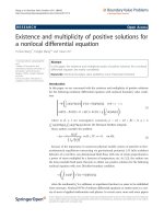
tion. Figure 6 illustrates the BER performance of consid-
ered single-user detectors for configuration I with N
u
= 8,
whereas Figure 7 represents performance for configuration
II with N
u
= 32, both in the full-load case.
The depicted curves obviously demonstrate efficiency of
MMSE-based detector compared to others techniques. Be-
sides, the two detectors using linear channel equalisation,
that is, ORC and MMSE detectors, are more sensitive to in-
accurate channel estimation than diversity combining detec-
tors such as EGC.
According to the presented configurations and the frame
structure, a tradeoff between the power allocated to pilot
symbols and the performance degradation resulting from
channel estimation errors should be found. A similar ap-
proach as described in [22] could be used.
In the following parts, we present the MC-CDMA system
implementation results and the different steps of our design
methodology used from system simulation to integration.
4. MODELISATION AND COMPLEXITY
ANALYSIS EVALUATION
4.1. Modelisation step
In our design approach and according to specifications given
Section 3, the CoMES methodology and its associated tool is
used to firstly model the studied MC-CDMA system with-
out any assumption about the architecture. The benefits of
this approach is that the model will both be used for func-
tional and architectural descriptions at an abstract level to
ease HW-SW distribution and to evaluate implementation
performances. The functional model is based on three com-
plementary viewpoints [23]:
(i) the structural organisation viewpoint, which repre-
sents data dependencies between functional elements,
is firstly specified. At the functional level, data are ex-
changed through ideal FIFO (first-in first-out) com-
munication ports;
MRC, N
s
= 100
EGC, N
s
= 100
ZF, N
s
= 100
MMSE, N
s
= 100
MRC, N
s
= 1000
EGC, N
s
= 1000
ZF, N
s
= 1000
MMSE, N
s
= 1000
510152025
E
b
/N
0
(dB)
10
−4
10
−3
10
−2
10
−1
BER
Figure 6: Performances results for configuration I, N
u
= 8.
MRC, N
s
= 100
EGC, N
s
= 100
ZF, N
s
= 100
MMSE, N
s
= 100
MRC, N
s
= 500
EGC, N
s
= 500
ZF, N
s
= 500
MMSE, N
s
= 500
5 10152025
E
b
/N
0
(dB)
10
−3
10
−2
10
−1
BER
Figure 7: Performances results for configuration II, N
u
= 32.
(ii) the behavioral viewpoint defines the set of operations
and their time order for each function. These two com-
plementary specifications are graphically defined;
(iii) the algorithm viewpoint is finally specified in C/C++
language and describes the set of instructions for each
operation previously defined.
This description approach leads to an efficient de-
sign with reduced errors propagation and to a fully ex-
ecutable model for system verification and performances
evaluation. The estimation of system performances uses an
1610 EURASIP Journal on Applied Signal Processing
Data generation
structure
Behavioural description
Modulation
Pilots
insertion
∗
N
s
Spreading
···
Behavioural model symbols:
Loop
Conditional wait
Data transmission
FIFO communication
Operation
(a)
Functional structures:
FFunction
I/O Data exchange
Functions execution state:
Data read or write
Data exchange
Function activity
Resource waiting
Functional attributes:
t
wr
Write/read duration
c
wr
Port capacity
t
f
Function duration
.
.
.
F Interleaving
I/O Spreaded data
F Spreading
I/O Modulated data
F Modulator
I/O DataE
F Data generation
t
wr
c
wr
t
f
Tempo ra l exe cution
Functions execution
···
···
···
···
···
···
(b)
Figure 8: Example of (a) the MC-CDMA system modelisation and (b) execution graph representation according to associated functional
attributes.
uninterpreted model, taking into account system attributes
such as operation durations, data exchange formats, FIFO ca-
pacity, and so forth. The CoMES simulation model is then
a true timed model and not only a functional model as
used by most of commercial simulators. To illustrate system
attributes influence, Figure 8 shows an MC-CDMA system
modelisation example and the associated execution graph at
the functional level. At this step, attributes can be set by de-
fault and will be more accurately determined once the func-
tions dur ations evaluation step is done.
Figure 9 illustrates CoMES tool system simulation ca-
pabilities at the structural viewpoint and at the algorithm
viewpoint. Moreover, generic parameters such as spreading
length, number of users, or equalisation techniques can be
set before simulation to obtain a flexible description and to
ease design space exploration.
Then, the MC-CDMA system could ful ly be modeled
using the CoMES tool. Besides, BER simulations were per-
formed to validate system behaviour and used algorithms.
This modelisation and functional validation is the first step
to achieve before function complexity analysis.
4.2. Complexity analysis evaluation
Complexity analysis step aims at defining each function com-
plexity and at investigating implementation performances
according to the processor target kind. From system mod-
elisation and specified algorithms, the CoMES tool allows
to evaluate functions activity and relative complexity thanks
to a profiling step. Complexity comparison illustrated in
Figure 10 indicates relative functions duration in system exe-
cution. Channel model description complexity has not been
represented. This step makes it possible to improve functions
Future Design and Implementation of MC-CDMA Systems 1611
Data evolution
BER evolution
Average power
evolution
Figure 9: Example of system simulation applying the CoMES methodology and using the associated tool. On the left-hand side, the struc-
tural simulation is based on an execution graph representation of functions activity, and on the right-hand side, algorithmic simulation
capabilities are presented.
Data generation
QPSK modulation
Spreading
Interleaving
MC modulation
MC demodulation
Equalisation
Deinterleaving
Despreading
QPSK demodulation
Data reception
0%
5%
10%
15%
20%
25%
Execution load
Figure 10: Function complexity evaluated for MC-CDMA config-
uration using N
u
= 32 and N
c
= 256.
description and coding style still without any architectural
assumption.
Besides, each function activity can also be measured.
Figure 11 illustrates the potential bottleneck represented by
MC modulation and demodulation compared to other func-
tions. Then, this function still remains the most computing
function in the considered MC-CDMA system.
This profiling step helps designers to identify critical
computing functions. In addition, for accurate architectural
design, we completed this complexity evaluation by con-
sidering functions implementation performances according
to processors targeted on our testbed platform [24]. Thus,
whereas OFDM modulation is efficiently performed by an
Data generation
QPSK modulation
Spreading
Interleaving
MC modulation
MC demodulation
Equalisation
Deinterleaving
Despreading
QPSK demodulation
Data reception
0%
10%
20%
30%
40%
50%
60%
70%
80%
90%
100%
Function activity
Active
Inactive
Resource waiting
Figure 11: Functions activity in system execution evaluated for
MC-CDMA configuration using N
u
= 32 and N
c
= 256.
inverse fast fourier transform (IFFT) algorithm, spreading
can conveniently be implemented using a fast hadamard
transform (FHT).
Results given in Table 4 highlight benefits of FPGA im-
plementation for most of the considered MC-CDMA func-
tions. Computation times are measured according to C6701
DSP clock, that is, 6 nanoseconds, and considering a 20
nanoseconds cycle for the FPGA.
These v alues measured by implementation of each ele-
mentary function on the testbed components are used in
order to find an efficient matching of MC-CDMA system
on the architecture and to evaluate performances achievable
with such a platform.
1612 EURASIP Journal on Applied Signal Processing
Table 4: Function implementation results in microseconds.
Parameters Parameters set C6701 DSP i mplementation FPGA implementation
QPSK modulation N
c
= 64, 256 0.9, 3.50.96, 3.84
Spreading N
u
= 4, 8, 16, 32, 64 0.642, 1.542, 3.624, 8.274, 18.684 0.08, 0.16, 0.32, 0.64, 1.28
Interleaving N
c
= 64, 256 1.1, 4.20.96, 3.84
OFDM modulation
N
c
= 64, 256 28.7, 146.718 3.84, 15.36
Channel estimation N
c
= 64, 256 0.7, 2.4 Not implemented
Equalisation N
c
= 64, 256 1.37, 4.83 3.84, 15.36
HW
processor
HW
interface
HW
interface
C
int
Communication
links
T
ex
1st SW
processor
SW
interface
SW
interface
SW
interface
C
conc
- S
over
2nd SW processor
SW
interface
C
conc
- S
over
Architectural attributes:
C
int
Interface capacity
C
conc
Software processor concurrency
T
ex
Data exchange duration
S
over
Software overhead
Figure 12: Architecture model using CoMES methodology.
5. ARCHITECTURAL DESIGN AND
IMPLEMENTATION RESULTS
5.1. Architectural design: functions distribution study
and implementation efficiency evaluation
The purpose of the architectural design step is to define an
efficient matching between the developed functions and the
available architecture. The CoMES methodology allows to
study the impact of functions distribution on the architec-
ture. Architectural attributes such as SW component concur-
rency, cycle duration for each component, SW overhead, and
intercomponent communications durations complete the ar-
chitecture description. We then modeled our platform as il-
lustrated in Figure 12.
Nevertheless, despite the fact that the CoMES tool is
still used as the performances evaluation method, the AAA
methodology is followed to ease the distribution step. In-
deed, this method and its associated tool SynDEx makes pos-
sible a quasiautomatic distribution and scheduling of the de-
fined system on the architecture, taking into account previ-
ous evaluated functions durations and communication costs.
Heuristic research is done to reduce system execution cycle.
An example of function distribution and scheduling on the
target architecture is illustrated in Figure 13.
Distribution
FPGA
Communication
port 1 DSP 1 DSP 2
0
Data generation
Data to modulation
QPSK modulation
Spreading
Interleaving
MC
modulation
MCMtochannel
Channel
Channel to MCM
MC
demodulation
Equalisation
Deinterleaving
Despreading
Demodulation
Demodulation to
data reception
Data reception
Estimated
computation time
Schedule
Figure 13: Matching exploration result.
Thanks to this exploration step, different distribution
performances can easily be investigated, improving the dif-
ficult task of HW-SW partition. The retained solution can
then be more accurately evaluated in the CoMES tool in
terms of pipelined behaviour. The concurrent simulation of
algorithms allocated on the architecture makes it possible,
on the one hand, to optimize the target architecture or, on
the other hand, to evaluate implementation performances at
an abstract level. Then, achievable throughputs according to
the architecture configuration can then be evaluated. Ta ble 5
gives examples of simulation results following the CoMES
methodology. The ideal case denotes results obtained ne-
glecting the communication ports influence. Others cases
takes into account the communication kind. It illustrates
poor efficiency of a fully SW implementation and the poten-
tial bottleneck represented by intercomponent communica-
tions.
Future Design and Implementation of MC-CDMA Systems 1613
Table 5: Implementation performances evaluation per user.
Parameters
Configuration I Configuration II
N
u
= 8, N
c
= 64 N
u
= 32, N
c
= 256
Fully SW implementation
Ideal 181 Kbps 36.4Kbps
Slow por t 93.9Kbps 31.4Kbps
Quick port 167 Kbps 35.8Kbps
HW-SW implementation
Ideal 2.9 Mbps 780 Kbps
Slow por t 444 Kbps 125 Kbps
Quick port 2.5 Kbps 645 Kbps
DSP 1 DSP 2 FPGA
17.07%
32.83%
50.10%
24.74%
29.76%
45.50%
78.99%
9.40%
11.60%
0%
10%
20%
30%
40%
50%
60%
70%
80%
90%
100%
Data processing
Data communication
Resources waiting
Figure 14: Component activity estimation for configuration II,
N
u
= 32, implemented on HW-SW architecture with quick ports.
Finally, the components activity can be measured for the
most satisfactory solution, as illustrated in Figure 14 for the
HW-SW implementation using quick ports.
Before implementation on the testbed platform, the last
step of the design process is the generation of the codes both
for the SW and the HW parts.
5.2. Hardware-Software code generation
and implementation results
As indicated in Figure 3, the AAA methodology is used in or-
der to generate codes at once for the SW, the HW part, and
the interfaces. The code generation process is described in
Figure 15. After the distribution step, the tool SynDEx makes
it possible to generate distributed executives for each com-
ponent. This code takes into account intercomponent syn-
chronisations and calls to functions. The code generation
uses specific libraries built according to the component kind.
The description of theses libraries will not be addressed in
the present paper, the reader should be refered to works de-
scribed in [25].
The benefits of this approach are the generation of fully
validated codes reducing the verification step once imple-
mentation on the testbed is done. The libraries used for SW
generation already exist [26]. We built the needed library for
HW generation [27]. This libr ary uses the different devel-
oped functions and the required interfaces. The main synthe-
System validation on
the prototyping board
DSP 1 DSP 2 FPGA
SynDEx code generation
C and VHDL
libraries
(communications,
functions)
Retained architectural solution
Figure 15: SynDEx code generation process.
sis results in terms of FPGA logic elements for each function
implemented in the HW part are given in Tab le 6.
For example, in the Configuration I case, the automatic
generation of the HW part of the transmitter retained so-
lution, both for the required interface and the computation
functions, corresponds to 1132 logic elements and 12 mem-
ory blocks. Then, the HW synthesis results made it possible
to fully validate this design at a 50 MHz frequency.
6. CONCLUSION
We have presented a codesign approach and associated tools
for the MC-CDMA system rapid prototyping on a mixed ar-
chitecture. This design goes from system specification and
simulation to HW-SW code generation and implementation
on a testbed platform. The use of the CoMES model allows
system simulations at the functional level as well a s at the ar-
chitectural one. Then, this top-down design approach makes
it possible to accurately evaluate system implementation ef-
ficiency, according to functions complexity and architecture
properties. Finally, the use of the AAA methodology com-
pletes this HW-SW design by covering the distribution and
code generation steps.
The described design process, applied to MC-CDMA sys-
tem, facilitates and reduces the development cycle. Then, we
easily investigate different implementation solutions accord-
ing to the considered HW platform. Besides, the benefits of
this approach fit into the SoftWare Radio (SWR) require-
ments for efficient design methods.
From our application’s point of view, evaluation results
and implementation show the ability to obtain high-speed
data rate using a mixed architecture. The demonstrated
1614 EURASIP Journal on Applied Signal Processing
Table 6: Synthesis results in terms of occupied logic elements for the HW implemented functions.
Parameters Configuration I Configuration II
Spreading 138 400
Interleaving 143 325
OFDM modulation 590 – 6 memory blocks 655 – 6 memory blocks
Equalisation 200 315
Quick communication ports 80 80
feasibility of the studied MC-CDMA system could lead to its
enhancement of the outdoor propagation characteristics.
ACKNOWLEDGMENT
This work has been partly carried out within the European
Union IST research project MATRICE (MC-CDMA trans-
mission techniques for integrated broadband cellular sys-
tems).
REFERENCES
[1] J. Pereira, “A personal perspective of fourth generation,”
Telektronikk, vol. 97, no. 1, pp. 20–30, 2001.
[2] M. Arndt, S. Martin, B. Miscopein, V. Bella, L. Bollea, and
E. Buracchini, “Software radio: the challenges for reconfig-
urable terminals,” Annals of Telecommunications, vol. 57, no.
7-8, pp. 570–612, 2002.
[3] S. Hara and R. Prasad, “Overview of multicarrier CDMA,”
IEEE Communications Magazine, vol. 35, no. 12, pp. 126–133,
1997.
[4] N. Yee, J. P. Linnartz, and G. Fettweis, “Multi-carrier CDMA
in indoor wireless radio networks,” in Proceedings of the IEEE
Personal Indoor and Mobile Radio Communications (PIMRC
’93), pp. 109–113, Yokohama, Japan, September 1993.
[5] K. Fazel and L. Papke, “On the performance of convolu-
tionally-coded CDMA/OFDM for mobile communication
system,” in Proceedings of the IEEE Personal Indoor and Mo-
bile Radio Communications (PIMRC ’93), pp. 468–472, Yoko-
hama, Japan, September 1993.
[6] A. Chouly, A. Brajal, and S. Jourdan, “Orthogonal multicar-
rier techniques applied to direct sequence spread spectrum
CDMA systems,” in Proceedings of G lobal Telecommunications
Conference (GLOBECOM ’93), pp. 1723–1728, Houston, Tex,
USA, November 1993.
[7] V. M. DaSilva and E. S. Sousa, “Performance of orthogo-
nal CDMA codes for quasi-synchronous communication sys-
tems,” in Proceedings of the IEEE International Conference
on Universal Personal Communications (ICUPC ’93), pp. 995–
999, Ottawa, Ont, Canada, October 1993.
[8] M. H
´
elard, R. Le Gouable, J F. H
´
elard, and J Y. Baudais,
“Multicarrier CDMA techniques for future wideband wireless
networks,” Annals of Telecommunications, vol. 56, no. 5-6, pp.
260–274, 2001.
[9] A. A. Kountouris, C. Moy, and L. Rambaud, “Reconfigurabil-
ity: a key property in software radio systems,” in First Karl-
shruhe Workshop on Software Radio, Karlshruhe, Germany,
March 2000.
[10] J. Staunst rup and W. Wolf, Hardware/Software Co-Design:
Principles and Practice, Kluwer Academic Publishers, Norwell,
Mass, USA, 1997.
[11] E. Haas, H. Lang, and M. Schnell, “Development and imple-
mentation of an advanced airport data link based on multi-
carrier communications,” European Transactions on Telecom-
munications, vol. 13, no. 5, pp. 447–454, 2002.
[12] A. C. McCormick, P. M. Grant, J. S. Thompson, T. Arslan, and
A. T. Erdogan, “Implementation of a SIC based MC-CDMA
base station receiver,” European Transactions on Telecommu-
nications, vol. 13, no. 5, pp. 513–518, 2002.
[13] A. C. McCormick, P. M. Grant, J. S. Thompson, T. Arslan, and
A. T. Erdogan, “A low power MMSE receiver architecture for
multi-carrier CDMA,” in Proceedings of IEEE International
Symposium on Circuits and Systems (ISCAS ’01), pp. 41–44,
Sydney, Australia, May 2001.
[14] S. Nobilet, J F. H
´
elard, and D. Mottier, “Spreading sequences
for uplink and downlink MC-CDMA systems: PAPR and MAI
minimization,” European Transactions on Telecommunica-
tions, vol. 13, no. 5, pp. 465–473, 2002.
[15] P. H
¨
oher,S.Kaiser,andP.Robertson, “Two-dimensional
pilot-symbol-aided channel estimation by Wiener filtering,”
in IEEE International Conference on Acoustics, Speech, and Sig-
nal Processing (ICASSP ’97), pp. 1845–1848, Munich, Ger-
many, April 1997.
[16] M. Vasilko, L. Machacek, M. Matej, P. Stepien, and S. Hol-
loway, “A rapid prototy ping methodology and platform for
seamless communication systems,” in Proceedings of 12th IEEE
International Workshop on Rapid System Prototyping (RSP
’01), pp. 70–76, Monterey, Calif, USA, June 2001.
[17] I. Seskar and N. B. Mandayam, “A software radio architecture
forlinearmultiuserdetection,” inConference on Information
Sciences and Systems, Princeton, NJ, USA, March 1998.
[18] J P. Calvez, Embedded Real-Time Systems: A Specification and
Design Methodology, vol. 23 of Wiley Series in Software Engi-
neering Practice Ser., John Wiley & Sons, New York, NY, USA,
1993.
[19] T. Grandpierre, C. Lavarenne, and Y. Sorel, “Optimized rapid
prototyping for real-time embedded heterogeneous multipro-
cessors,” in Proceedings of the 7th International Workshop on
Hardware/Software Codesign (CODES ’99), pp. 74–78, New
York, NY, USA, May 1999.
[20] ETSI, “Project Broadband Radio Access Networks (BRAN),
HIPERLAN Type 2; Physical layer,” Technical specification,
October 1999.
[21] S. Kaiser, Multi-carrier CDMA mobile radio system-analysis
and optimization of detection, decoding, and channel estima-
tion, Ph.D. thesis, University of Munich, Munich, Germany,
1998.
[22] T. S
¨
alzer, D. Mottier, and L. Brunel, “Influence of system
load on channel estimation in MC-CDMA mobile radio com-
munication systems,” in Proceedings IEEE Vehicular Technol-
og y Conference (VTC ’01), pp. 522–526, Rhodes, Greece, May
2001.
[23] J. P. Calvez, D. Heller, and O. Pasquier, “Uninterpreted co-
simulation for performance evaluation of Hw/Sw systems,” in
4th International Workshop on Hardware/Software Co-Design
(CODES/CASHE ’96), pp. 132–139, Pittsburgh, Pa, USA,
March 1996.
[24] J F. H
´
elard, F. Nouvel, and S. Le Nours, “A MC-CDMA sys-
tem analysis in a software radio context,” Annals of Telecom-
munications, vol. 57, no. 7-8, pp. 699–720, 2002.
[25] V. Fresse, O. D
´
eforges, and J F. Nezan, “AVSynDEx: a
rapid prototyping process dedicated to the implementation of
Future Design and Implementation of MC-CDMA Systems 1615
digital image processing applications on multi-DSP and
FPGA architectures,” EURASIP Journal on Applied Signal Pro-
cessing, vol. 2002, no. 9, pp. 990–1002, 2002.
[26] Y. Le Mener, M. Raulet, J F. Nezan, A. Kountouris, and
C. Moy, “SynDEx executive kernel development for DSPs TI
C6X applied to real-time and embedded multiprocessors ar-
chitectures,” in Proc.11thEuropeanSignalProcessingConfer-
ence (EUSIPCO ’02), Toulouse, France, September 2002.
[27] F. Nouvel, S. Le Nours, and I. Hermann, “AAA methodology
and SynDEx tool capabilities for designing on heterogeneous
architecture,” in 18th Conference on Desig n of Circuits and In-
tegrated Systems (DCIS ’03), Ciudad Real, Spain, November
2003.
S
´
ebastien Le Nours received the Engineer-
ing degree in electronics from the ISEN
School, Brest, France, in 2000. In 2003,
he received the Ph.D. degree in electron-
ics from the National Institute of Applied
Sciences (INSA), Rennes, France. His re-
search interests include design methodolo-
gies for embedded systems and signal pro-
cessing techniques, with particular empha-
sis on multicarrier spread spectrum for mo-
bile communications. He is currently working as an Assistant Pro-
fessor at the UBS University and is associated to the LESTER labo-
ratory, Lorient, France.
Fabienne Nouvel received the Engineering
degree in electronics from the National In-
stitute of Applied Sciences (INSA), Rennes,
France, in 1985. She worked for 5 years in
networks domains. In 1994, she received
the Ph.D. degree in electronics from the
INSA, Rennes. Since 1995, she has been an
Associate Professor at INSA in electronics.
Her research topics include electronics, sig-
nal processing techniques, especially spread
spectrum for embedded indoor and outdoor communications, and
design methodologies for heterogeneous systems.
Jean-Franc¸ois H
´
elard received his Dipl
Ing. degree from the National Institute of
Applied Sciences (INSA), Rennes, France, in
1981. From 1982 to 1997, he was a Research
Engineer and then Head of the channel cod-
ing for digital broadcasting research group
at the CCETT (France Telecom Research
Center) in Rennes, where he worked succes-
sively on digital audio broadcasting within
EUREKA 147 DAB (digital audio broad-
casting) and terrestrial digital video broadcasting (DVB-T) within
the framework of the European project dTTb. In 1992, he received
the Ph.D. degree in electronics and joined INSA in 1997, where he is
currently a Professor and Head of the group Systems, Propagation
and Radars of the Rennes Institute for Electronics and Telecom-
munications (IETR) which depends on the French National Centre
for Scientific Research (CNRS). His present research interests lie in
signal processing techniques for digital communications, as space-
time and channel coding, multicarrier modulation, spread spec-
trum, and multiuser communications. He is the author or coauthor
of more than 48 technical papers in international scientific journals
and conferences, and holds 11 European patents.