PDHONLINE COURSE H140 (2 PDH) OPEN CHANNEL HYDRAULICS III – SHARP- CRESTED WEIRS 2020
Bạn đang xem bản rút gọn của tài liệu. Xem và tải ngay bản đầy đủ của tài liệu tại đây (601.7 KB, 20 trang )
PDHonline Course H140 (2 PDH)
Open Channel Hydraulics III – Sharp-
crested Weirs
Instructor: Harlan H. Bengtson, Ph.D., PE
2020
PDH Online | PDH Center
5272 Meadow Estates Drive
Fairfax, VA 22030-6658
Phone: 703-988-0088
www.PDHonline.com
An Approved Continuing Education Provider
www.PDHcenter.com PDH Course H140 www.PDHonline.org
Open Channel Hydraulics III - Sharp-crested Weirs
Harlan H. Bengtson, Ph.D., P.E.
COURSE CONTENT
1. Introduction
This course is intended to be taken after the course, H138, “Open Channel
Hydraulics I – Uniform Flow.” It will be assumed that anyone taking this course
is familiar with the major classifications used for open channel flow (steady or
unsteady state, laminar or turbulent flow, uniform or non-uniform flow, and
critical, subcritical or supercritical flow) and with equations and calculations for
uniform open channel flow.
A weir, widely used for measurement of open channel flow rate, consists of an
obstruction in the path of flow. Water rises above the obstruction to flow over it,
and the height of water above the obstruction can be correlated with the flow rate.
The top of the weir, over which the liquid flows, is called the crest of the weir.
Two commonly used types of weir are the sharp-crested weir and broad-crested
weir. The sharp-crested weir will be covered in this course. The emphasis will
be on calculations used for flow rate over the various types of sharp-crested
weirs, but there will also be information on guidelines for installation and use of
sharp-crested weirs.
2. General Information on Sharp-Crested Weirs
A sharp-crested weir is a vertical flat plate with a sharp edge at the top, over
which the liquid must flow in order to drop into the pool below the weir.
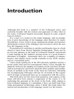
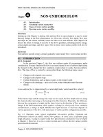
Figure 1, on the next page, shows a longitudinal section of flow over a sharp-
crested weir.
Some of the terminology used in connection with sharp-crested weirs will be
presented and discussed briefly here. As shown in Figure 1, nappe is a term used
to refer to the sheet of water flowing over the weir. Drawdown, as shown in
©2009 Harlan H. Bengtson Page 2 of 20
www.PDHcenter.com PDH Course H140 www.PDHonline.org
Figure 1, occurs upstream of the weir plate due to the acceleration of the water as
it approaches the weir. Free flow is said to occur with a sharp-crested weir, when
Figure 1. Longitudinal Section, Flow Over Sharp-crested Weir
there is free access of air under the nappe. The Velocity of approach is equal to
the discharge, Q, divided by the cross-sectional area of flow at the head
measuring station, which should be upstream far enough that it is not affected by
the drawdown. The condition which occurs when downstream water rises above
the weir crest elevation is called submerged flow or a submerged weir. The
equations to be discussed for sharp-crested weirs all require free flow conditions.
Accurate measurement of flow rate is not possible under submerged flow
conditions.
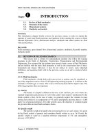
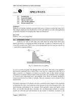
The three common sharp-crested weir shapes shown in Figure 2 will be
considered in some detail in this course. These shapes are suppressed
rectangular, V-notch, and contracted rectangular.
Figure 2. Common Sharp-crested Weir Shapes
©2009 Harlan H. Bengtson Page 3 of 20
www.PDHcenter.com PDH Course H140 www.PDHonline.org
The reference for the equations, graphs, etc to be used for calculating flow rate
over a weir from measured values such as the head over the weir and various weir
parameters, will be the 2001 revision, of the 1997 third edition, of the Water
Measurement Manual, produced by the U.S. Dept. of the Interior, Bureau of
Reclamation. Water Measurement Manual is available for on-line use or free
download at: .
This reference has very extensive coverage of water flow rate measurement. It is
primarily oriented toward open channel flow, but has some discussion of pipe
flow (closed conduit pressurized flow) also.
3. Suppressed Rectangular Weirs
The suppressed rectangular, sharp-crested weir, shown in Figure 2 (a), has the
weir length equal to the width of the channel. The term suppressed is used to
mean that the end contractions, as shown in Figure 2 (c), are suppressed (not
present).
The Kindsvater-Carter method (from ref #3 for this course) is recommended in
Water Measurement Manual, as a method with flexibility and a wide range of
applicability. This method, for a sharp-crested rectangular weir, will be presented
and discussed here. A more simplified equation, which works well if particular
requirements are met, will then be presented and discussed as another alternative.
The Kindsvater-Carter equation for a rectangular, sharp-crested weir (suppressed
or contracted) is:
Q = Ce Le He3/2 (1)
where:
Q = discharge, ft3/s
e = a subscript denoting "effective"
Ce = effective coefficient of discharge, ft1/2/s
Le = L + kb
©2009 Harlan H. Bengtson Page 4 of 20
www.PDHcenter.com PDH Course H140 www.PDHonline.org
He = H + kh
In these relationships:
kb = a correction factor to obtain effective weir length
L = measured length of weir crest
B = average width of approach channel, ft
H = head measured above the weir crest, ft
kh = a correction factor with a value of 0.003 ft
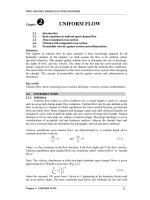
The factor kh has a constant value equal to 0.003 ft. The factor kb varies with the
ratio of crest length to average width of approach channel (L/B). Values of kb for
ratios of L/B from 0 to 1 are available from Figure 3 (as given in Water
Measurement Manual).
Figure 3. kb as a function of L/B (as given in Water Measurement Manual)
The effective coefficient of discharge, Ce, includes effects of relative depth and
relative width of the approach channel. Thus, Ce is a function of H/P and L/B.
Values of Ce may be obtained from the family of curves given in Figure 4 (as
given in Water Measurement Manual). Also, values of Ce may be calculated
from the equations given after Figure 4.
©2009 Harlan H. Bengtson Page 5 of 20
www.PDHcenter.com PDH Course H140 www.PDHonline.org
As shown in Figure 1, P is the vertical distance to the weir crest from the
approach pool invert. (NOTE: The term “invert” means the inside, upper surface
of the channel.)
Figure 4. Ce as a function of H/P & L/B for Rect. Sharp-crested Weir
The straight lines in figure 4 have the equation form:
Where the equation constants, C1 and C2, in equation (2) are functions of L/B as
shown in Table 1, (from Water Measurement Manual) given below.
©2009 Harlan H. Bengtson Page 6 of 20
www.PDHcenter.com PDH Course H140 www.PDHonline.org
Table 1. Values of C1 & C2 for equation (7) (from Water Measurement Manual)
L/B C1 C2
0.2 -0.0087 3.152
3.164
0.4 0.0317 3.173
3.178
0.5 0.0612 3.182
3.189
0.6 0.0995 3.205
3.220
0.7 0.1602
0.8 0.2376
0.9 0.3447
1.0 0.4000
Although the Kindsvater-Carter equation for a rectangular, sharp-crested weir,
seems rather complicated as presented on the last three pages, it simplifies a great
deal for a suppressed rectangular weir (L = B or L/B = 1.0). Equation (2)
becomes:
From Figure 3 (L/B= 1): kb = - 0.003, so: Le = L + kb = L - 0.003
As given above: kh = 0.003, so: He = H + kh = H + 0.003
Substituting for Ce, Le, & He into equation (1), gives the following Kindsvater-
Carter equation for a suppressed rectangular, sharp-crested weir:
(Keep in mind that equation (3) is a dimensional equation with Q in cfs and
H, P, & L in ft.)
©2009 Harlan H. Bengtson Page 7 of 20
www.PDHcenter.com PDH Course H140 www.PDHonline.org
The Bureau of Reclamation, in their Water Measurement Manual, gives equation
(4) below, as an equation suitable for use with suppressed rectangular, sharp-
crested weirs if the accompanying conditions are met:
(U.S. units: Q in cfs, B & H in ft): Q = 3.33 B H3/2 (4)
To be used only if:
Converting equation (4) to S.I. units gives the following:
(S.I. units: Q in m3/s, B & H in m): Q = 1.84 B H3/2 (5)
To be used only if:
Example #1: There is a suppressed rectangular weir in a 2 ft wide rectangular
channel. The weir crest is 1 ft above the channel invert. Calculate the flow rate
for H = 0.2, 0.3, 0.4, 0.8, 1.0 ft, & 1.25 ft, using equations (3) & (4).
Solution: From the problem statement, L = B = 2 ft, and P = 1 ft, so it is
necessary simply to substitute values into the two equations and calculate Q for
each value of H. The calculations were made using an Excel spreadsheet. The
results are shown in the table below, where Q3 is calculated from equation (3) and
Q4 is calculated from equation (4).
H, ft: 0.2 0.3 0.4 0.8 1.0 1.25 (= H/P)
Q3, cfs: 0.603 1.112 1.727 5.087 7.262 10.42
Q4, cfs: 0.596 1.094 1.685 4.766 6.660 9.308
0.1 0.15 0.2 0.4 0.625
H/B: 0.5
©2009 Harlan H. Bengtson Page 8 of 20
www.PDHcenter.com PDH Course H140 www.PDHonline.org
Discussion of results: Since P = 1 ft in this example, the values for H in the
table of results are equal to H/P. The values for H/B are shown in the table also.
Wow, is this all Note that the results for equation (3), the Kindsvater-Carter
really discussion equation, and equation (4) the simpler equation agree quite
closely for the three smaller values of H. They are the
of results ? same to two significant figures for those three H values.
The two conditions for the use of equation (4) are met only
for the two smallest H values. For H = 0.4 ft, H/P is just
above the allowable maximum of 0.33. For the three
largest values of H, both H/P and H/B are larger than the
allowable values for use of equation (4), and the
equation (4) results are quite a bit different from those
for equation (5).
Conclusions: For a suppressed rectangular, sharp-crested weir, equation (4),
Q = 3.33BH3/2, may be used if H/P < 0.33 & H/B < 0.33. For H/P > 0.33
or H/B > 0.33, the Kindsvater-Carter equation [equation (4)] should be used.
4. Contracted Rectangular Weirs
The contracted rectangular sharp-crested weir, shown in Figure 2c and in the
figure below, has weir length, L, less than the width of the channel, B. This is
sometimes called an unsuppressed rectangular weir.
©2009 Harlan H. Bengtson Page 9 of 20
www.PDHcenter.com PDH Course H140 www.PDHonline.org
For a contracted rectangular, sharp-crested weir (L/B < 1), the Kindsvater-
Carter equation becomes:
Where: C1 and C2 come from Table 1 and kb comes from Figure 3, for a
known value of L/B. (Table 1 and Figure 3 are on pages 4 & 5.)
The Bureau of Reclamation, in its Water Measurement Manual, gives equation
(7) below as a commonly used, simpler Equation for a fully contracted
rectangular weir, subject to the accompanying conditions:
(U.S. units: Q in cfs, L & H in ft): Q = 3.33(L – 0.2 H)(H3/2) (7)
The equivalent equation for S.I. units is:
(S.I. units: Q in m3/s, L & H in m): Q = 1.84(L – 0.2 H)(H3/2) (8)
For both equation (7) and equation (8), the following conditions must be met:
i) Weir is fully contracted, i.e.: B – L > 4 Hmax and P > 2 Hmax
ii) H/L < 0.33
Example #2: Consider a contracted rectangular weir in a rectangular channel
with B, L, H, & P having each of the following sets of values.
a) Determine whether the conditions for use of equation (7) are met for
each set of values.
b) Calculate the flow rate, Q, using equations (6) & (7) for each set of
values.
©2009 Harlan H. Bengtson Page 10 of 20
www.PDHcenter.com PDH Course H140 www.PDHonline.org
i) B = 4 ft, L = 2 ft, H = 0.5 ft, P = 1 ft
ii) B = 10 ft, L = 6 ft, H = 0.8 ft, P = 2 ft
iii) B = 10 ft, L = 4 ft, H = 1 ft, P = 2.4 ft
iv) B = 10 ft, L = 4 ft, H = 2 ft, P = 2 ft
v) B = 10 ft, L = 8 ft, H = 2 ft, P = 1.5 ft
Solution: a) The required conditions for use of equation (7) are:
1) B – L > 4 Hmax, 2) P > 2 Hmax & 3) H/L < 0.33
i) B – L = 2 ft & 4 H = 2 ft, so condition 1 is barely met
P = 2 ft & 2 H = 2 ft, so condition 2 is barely met
H/L = 0.5/2 = 0.25 < 0.33, so condition 3 is met
ii) B – L = 4 ft & 4 H = 3.2 ft, so condition 1 is met
P = 2 ft & 2 H = 1.6 ft, so condition 2 is met
H/L = 0.8/6 = 0.13 < 0.33, so condition 3 is met
iii) B – L = 6 ft & 4 H = 4 ft, so condition 1 is met
P = 2.4 ft & 2 H = 2 ft, so condition 2 is met
H/L = 1/4 = 0.25 < 0.33, so condition 3 is met
iv) B – L = 6 ft & 4 H = 8 ft, so condition 1 is not met
P = 2 ft & 2 H = 4 ft, so condition 2 is not met
H/L = 2/4 = 0.5 > 0.33, so condition 3 is not met
©2009 Harlan H. Bengtson Page 11 of 20
www.PDHcenter.com PDH Course H140 www.PDHonline.org
v) B – L = 2 ft & 4 H = 8 ft, so condition 1 is not met
P = 1.5 ft & 2 H = 4 ft, so condition 2 is not met
H/L = 2/8 = 0.25 < 0.33, so condition 3 is met
Hey, This is a pretty b) The calculations for part b) were done with an
long solution isn't it ? Excel spreadsheet. The results are summarized in
the table below. The flow rates from equation (7)
was calculated using the given values for L, P & H.
In order to use equation (6), values were needed
for C1, C2, & kb. All three are functions of L/B.
Values for C1, & C2 were obtained from Table 1,
and values for kb were obtained from Figure 3.
Q6 & Q7, are the flow rates from equations
(6) & (7) respectively.
eqn (7) ok? i) ii) iii) iv) v)
L/B yes yes yes no no
C1 0.5 0.6 0.4 0.4 0.8
C2 0.612 0.0995 0.0317 0.0317 0.2376
kb 3.173 3.178 3.164 3.164 3.189
Q6, cfs 0.010 0.012 0.009 0.009 0.014
Q7, cfs 2.330 14.12 12.87 36.37 80.13
2.237 13.92 12.65 33.91 71.58
Discussion of Results: Both equations give similar results for cases i), ii), & iii),
where the criteria for use of the simpler Equation (7) were met (B – L > 4 Hmax,
P > 2 Hmax, & H/L < 0.33). The results for the two equations differ
considerably for cases iv) and v), where the criteria were not met.
©2009 Harlan H. Bengtson Page 12 of 20
www.PDHcenter.com PDH Course H140 www.PDHonline.org
Conclusions: For a contracted rectangular, sharp-crested weir, the simpler
equation [Q = 3.33(L – 0.2 H)(H3/2) ], appears to be adequate when the three
criteria mentioned above are met. This equation is also acceptable to the U.S.
Bureau of Land Reclamation for use when those criteria are met. The U. S.
Bureau of Land Reclamation recommends the use of the slightly more
complicated Kindsvater-Carter equation [equation (6)] for use when any of the
three criteria given above for use of the simpler Equation (7) are not met.
5. V-Notch Weirs
The V-notch, sharp-crested weir (also called a triangular weir), shown in Figure
2 (b) and in Figure 5, below, measures low flow rates better than the rectangular
weir, because the flow area decreases as H decreases and reasonable heads are
developed even at small flowrates.
The Bureau of Reclamation, in their Water Measurement Manual, gives equation
(9) (see below) as an equation suitable for use with a fully contracted, 90o
V-notch, sharp-crested weir if it meets the indicated conditions.
(U.S. units: Q in cfs, H in ft) Q = 2.49 H2.48 (9)
Subject to: P > 2 Hmax, S > 2 Hmax, 0.2 ft < H < 1.25 ft
Where: Hmax = the maximum head expected over the weir
P = the height of the V-notch vertex above the channel invert
S = the distance from the channel wall to the to the V-notch
edge at the top of the overflow
See Figure 5, below, for additional clarification of the parameters S, P, & H.
©2009 Harlan H. Bengtson Page 13 of 20
www.PDHcenter.com PDH Course H140 www.PDHonline.org
Figure 5. Fully Contracted V-notch Weir
A 90o V-notch weir is better than a rectangular weir for measuring relatively low
flow rates and a rectangular weir is better for measuring higher flow rates. This
will be illustrated with the next couple of examples.
Example #3: Calculate the minimum and maximum flow rates covered by the
recommended range of 0.2 ft to 1.25 ft for the head over a fully contracted 90o V-
notch weir. (Note: in order to be fully contracted, P = 2 Hmax = 2.5 ft.)
Solution: Substituting values of H into equation (9) gives:
Qmin = (2.49)(0.22.48) = 0.046 cfs = Qmin
Qmax = (2.49)(1.252.48) = 4.33 cfs = Qmax
Example #4: Calculate the minimum and maximum flow rates covered by the
range of 0.2 ft to 1.25 ft for the head over a suppressed rectangular weir in a 2 ft
wide rectangular channel. Assume that P = 2.5 ft, as with the V-notch example,
so that the suppressed rectangular weir is fully contracted from the channel
bottom.
Solution: Equation (4) can be used for H = 0.2 ft, because H/P < 0.33 and H/B <
0.33, however for H = 1.25 ft, H/B & H/P are both greater than 0.33, so equation
(3) must be used. The calculations are shown below:
Qmin = (3.33)(2)(0.23/2) = 0.596 cfs = Qmin
©2009 Harlan H. Bengtson Page 14 of 20
www.PDHcenter.com PDH Course H140 www.PDHonline.org
Qmax = [3.32 + 0.40(1.25/2.5)](2 – 0.003)[(2 + 0.003)3/2] = 10.42 cfs = Qmax
Comments: As shown by Example #3 and Example #4, the 2 ft rectangular
weir can carry more than twice the flow rate that the V-notch weir can carry for
the same head above the channel bottom, however the V-notch weir can measure
a much smaller flow rate than is possible with the rectangular weir.
Notch angles other than 90o in a V-notch, sharp-crested weir require the use of
the Kindsvater-Carter equation, as given in Water Measurement Manual:
Where: Q = discharge over weir, cfs
Ce = effective discharge coefficient
H = head on weir in ft
k = head correction factor
θ = angle of V-notch
Ce, the effective weir coefficient, and k, the head correction factor, are both
functions of θ only if the V-notch weir is fully contracted (P > 2 Hmax &
S > 2 Hmax). See Figure 5 on page 13, for clarification of the parameters P and
H. Ce can be obtained from figure 6* or equation (11)*, and k, can be obtained
from figure 7* or equation (12)*.
*from LMNO Engineering, Research and Software, Ltd website, at:
/>
©2009 Harlan H. Bengtson Page 15 of 20
www.PDHcenter.com PDH Course H140 www.PDHonline.org
V-notch Weir Effective Coefficient
0.5950
0.5900
C e 0.5850
0.5800
0.5750 20 40 60 80 100 120
0
Notch angle, θ
Figure 6. Effective V-notch Weir Coefficient, Ce
Ce = 0.607165052 – (0.000874466963)θ + (6.10393334 x 10⁻⁶)θ2 (11)
Figure 7. V-notch Weir, Head Correction Factor, k
©2009 Harlan H. Bengtson Page 16 of 20
www.PDHcenter.com PDH Course H140 www.PDHonline.org
k = 0.0144902648 – (0.00033955535)θ
+ (3.29819003 x 10⁻⁶)θ2 – (1.06215442 x 10⁻⁸)θ3 (12)
Example #5: Estimate the flow rate through a fully contracted V-notch weir for
a head of 0.2 feet and for a head of 1.25 feet.
a) with a notch angle of 60o
b) with a notch angle of 40o
Solution: Part a) From equation (11) & (12), with θ = 60o:
Ce = 0.5767 & k = 0.0037
Substituting into equation (10), with H = 0.2 ft, gives: (θ = 60o, H = 0.2 ft)
Q = (4.28)(0.5767)[tan(30o)] [(0.2 + 0.0037)5/2] = 0.0267 cfs
Substituting into equation (10), with H = 1.25 ft, gives: (θ = 60o, H = 1.25 ft)
Q = (4.28)(0.5767)[tan(30o)] [(1.25 + 0.0037)5/2] = 2.508 cfs
Part b) From equation (11) & (12), with θ = 40o: Ce = 0.5820 & k = 0.0051
Substituting into equation (10), with H = 0.2 ft, gives: (θ = 40o, H = 0.2 ft)
Q = (4.28)(0.5820)[tan(20o)] [(0.2 + 0.0051)5/2] = 0.0173 cfs
Substituting into equation (10), with H = 1.25 ft, gives: (θ = 40o, H = 1.25 ft)
Q = (4.28)(0.5820)[tan(20o)] [(1.25 + 0.0051)5/2] = 1.600 cfs
©2009 Harlan H. Bengtson Page 17 of 20
www.PDHcenter.com PDH Course H140 www.PDHonline.org
Comment: This example is intended to simply illustrate the use of equations
(10), (11), & (12) for V-notch weirs with notch angles other than 90o.
6. Installation & Use Guidelines for Sharp-Crested Weirs
A summary of installation and measurement guidelines for sharp-crested weirs
extracted from Water Measurement Manual, is given in this section.
a) The upstream face of the weir plates and bulkhead should be plumb, smooth,
and normal to the axis of the channel.
b) The entire crest should be level for rectangular and trapezoidal shaped weir
openings, and the bisector of V-notch angles should be plumb.
c) The top thickness of the crest and side plates should be between 0.03 and 0.08
inch.
d) The upstream edges of the weir opening plates must be straight and sharp.
Edges of plates require machining or filing perpendicular to the upstream face to
remove burrs or scratches and should not be smoothed off with abrasive cloth or
paper. Avoid knife edges because they are a safety hazard and damage easily
e) The overflow sheet or nappe should touch only the upstream faces of the crest
and side plates.
f) Maximum downstream water surface level should be at least 0.2 ft below crest
elevation. However, when measuring close to the crest, frequent observations are
necessary to verify that the nappe is continually ventilated without waves
periodically filling the under nappe cavity.
g) The measurement of head on the weir is the difference in elevation between the
crest and the water surface at a point located upstream from the weir a distance of
at least four times the maximum head on the crest.
h) The approach to the weir crest must be kept free of sediment deposits.
i) If the weir crest length is greater than 50% of the approach channel width, then
ten average approach flow widths of straight, unobstructed approach are required.
©2009 Harlan H. Bengtson Page 18 of 20
www.PDHcenter.com PDH Course H140 www.PDHonline.org
j) If the weir crest length is less than 50% of the approach channel width, then
twenty average approach flow widths of straight, unobstructed approach are
required.
k) If upstream flow is below critical depth, a jump should be forced to occur. In
this case, thirty measuring heads of straight, unobstructed approach after the jump
should be provided.
l) The minimum head over the weir should be 0.2 ft.
For Rectangular, Sharp-crested Weirs:
All of the general conditions, a) through l) above, apply. Also:
a) The crest length, L, should be at least 6 inches.
b) The crest height, P, should be at least 4 inches.
c) Values of H/P should be less than 2.4.
For V-notch Weirs:
All of the general conditions, a) through l) above, apply. Also:
a) For a fully contracted V-notch weir, the maximum measuring head should be
less than 1.25 ft.
b) For a fully contracted V-notch weir, H/B should be less than 0.2.
c) The average width of the approach channel, B, should always be greater than 3
ft for a fully contracted V-notch.
d) The V-notch of the weir should always be at least 1.5 ft above the invert of the
weir pool for a fully contracted V-notch.
©2009 Harlan H. Bengtson Page 19 of 20
www.PDHcenter.com PDH Course H140 www.PDHonline.org
7. Summary
Sharp-crested weirs are commonly used for flow rate measurement in open
channels. Three types of sharp-crested weirs: suppressed rectangular, contracted
rectangular, and V-notch, are covered in detail in this course. Emphasis is on
calculation of flow rate over a weir for given head over the weir and weir/channel
dimensions. For each of the three types of sharp-crested weir, a general equation
with a wide range of applicability is presented and discussed along with equations
and/or graphs as needed for use with the main equation. Also, for each of the
three types of sharp-crested weir, a simpler equation is presented along with a set
of conditions under which the simpler equation can be used. Several worked
examples are included covering all three types of weirs. Practical installation and
use guidelines for sharp-crested weirs are presented.
©2009 Harlan H. Bengtson Page 20 of 20