ISO 282781:2011 Glass in building — Glass products for structural sealant glazing — Part 1: Supported and unsupported monolithic and multiple glazing
Bạn đang xem bản rút gọn của tài liệu. Xem và tải ngay bản đầy đủ của tài liệu tại đây (860.11 KB, 68 trang )
INTERNATIONAL ISO
STANDARD 28278-1
First edition
2011-12-01
Glass in building — Glass products for
structural sealant glazing —
Part 1:
Supported and unsupported monolithic
and multiple glazing
Verre dans la construction — Produits verriers pour vitrage extérieur
collé —
Partie 1: Vitrages monolithiques ou multiples, supportés ou non
supportés
Reference number
ISO 28728-1:2011(E)
© ISO 2011
ISO 28728-1:2011(E)
COPYRIGHT PROTECTED DOCUMENT
© ISO 2011
All rights reserved. Unless otherwise specified, no part of this publication may be reproduced or utilized in any form or by any means,
electronic or mechanical, including photocopying and microfilm, without permission in writing from either ISO at the address below or
ISO's member body in the country of the requester.
ISO copyright office
Case postale 56 CH-1211 Geneva 20
Tel. + 41 22 749 01 11
Fax + 41 22 749 09 47
Web www.iso.org
Published in Switzerland
ii © ISO 2011 – All rights reserved
ISO 28728-1:2011(E)
Contents Page
Foreword ............................................................................................................................................................iv
1 Scope ...................................................................................................................................................... 1
2 Normative references............................................................................................................................1
3 Terms and definitions ........................................................................................................................... 2
4 Symbols and abbreviated terms .......................................................................................................... 6
5 Principle ................................................................................................................................................. 8
6 Required characteristics of glass products ..................................................................................... 10
6.1 Appropriate glass products ............................................................................................................... 10
6.2 Dimensional tolerances ...................................................................................................................... 11
6.3 Glass shapes ....................................................................................................................................... 12
6.4 Corners, notches and holes ............................................................................................................... 12
7 Verification of the suitability of glass products for use in SSG systems when exposed to
ultra-violet (UV) radiation.................................................................................................................... 13
7.1 General ................................................................................................................................................. 13
7.2 Insulating glass unit (IGU) .................................................................................................................. 13
7.3 Laminated glass or monolithic glass — Situation 3 (see Figure 3) ............................................... 15
7.4 Assessment of the adhesion between the sealant and the glass ..................................................15
8 Design ................................................................................................................................................... 16
8.1 Calculation of the thickness of the glass..........................................................................................16
8.2 Calculation of the height of the outer sealant of the IGU for supported and unsupported
glazing .................................................................................................................................................. 16
8.3 Calculation of the height of the outer sealant of the IGU for unsupported glazing ..................... 20
Annex A (informative) Assembly requirement ............................................................................................... 21
Annex B (normative) Structural and/or ultra-violet (UV) -resistant sealant (for use with structural
sealant glazing and/or IGUs with exposed seals) ............................................................................26
Annex C (normative) Evaluation of tests results...........................................................................................42
Annex D (normative) Shear at 23 °C — Test method .................................................................................... 46
Annex E (normative) Factory production control (FPC) requirements for sealants..................................48
Annex F (normative) Outer seal of an IGU — Category differentiation ....................................................... 53
Annex G (normative) Formation of bubbles...................................................................................................56
Annex H (informative) Sealing, structural bonding and UV resistance schematic illustrations .............. 57
Annex I (normative) Initial testing of the bonding of sealant to a non-glass substrate ............................ 60
Bibliography...................................................................................................................................................... 62
© ISO 2011 – All rights reserved iii
ISO 28728-1:2011(E)
Foreword
ISO (the International Organization for Standardization) is a worldwide federation of national standards bodies
(ISO member bodies). The work of preparing International Standards is normally carried out through ISO
technical committees. Each member body interested in a subject for which a technical committee has been
established has the right to be represented on that committee. International organizations, governmental and
non-governmental, in liaison with ISO, also take part in the work. ISO collaborates closely with the
International Electrotechnical Commission (IEC) on all matters of electrotechnical standardization.
International Standards are drafted in accordance with the rules given in the ISO/IEC Directives, Part 2.
The main task of technical committees is to prepare International Standards. Draft International Standards
adopted by the technical committees are circulated to the member bodies for voting. Publication as an
International Standard requires approval by at least 75 % of the member bodies casting a vote.
Attention is drawn to the possibility that some of the elements of this document may be the subject of patent
rights. ISO shall not be held responsible for identifying any or all such patent rights.
ISO 28728-1 was prepared by Technical Committee ISO/TC 160, Glass in building, Subcommittee SC 2, Use
considerations.
ISO 28728 consists of the following parts, under the general title Glass in building — Glass products for
structural sealant glazing:
Part 1: Supported and unsupported monolithic and multiple glazing
Part 2: Assembly rules
iv © ISO 2011 – All rights reserved
INTERNATIONAL STANDARD ISO 28728-1:2011(E)
Glass in building — Glass products for structural sealant
glazing —
Part 1:
Supported and unsupported monolithic and multiple glazing
1 Scope
This part of ISO 28278 specifies requirements for the suitability of supported and unsupported glass products
(see Figure 1) for use in the structural sealant glazing (SSG) technique. Regarding glass products, this part of
ISO 28278 constitutes a supplement to the requirements specified in the corresponding ISO standards with
regard to verifying suitability for use in SSG systems.
Only soda lime silicate glass is taken into consideration in this part of ISO 28278.
The glass products are installed and bonded into the support under controlled environmental conditions, as
described in ISO 28278-2.
Plastic glazing is excluded from the scope of this part of ISO 28278.
The structural, weatherproofing and sealant and outer seal of insulating glass unit (IGU) products, which are
commonly used in structural glazing applications, are those based on organo-siloxane, “silicone” polymers,
and recommended for use by the sealant manufacturer. Where there is a risk of earthquake, the sealant
design may not be sufficient to resist the loads, and complementary arrangements may be necessary.
This part of ISO 28278 does not preclude the use of other sealant types where these can demonstrate
suitability for service according to this part of ISO 28278 and when used following the recommendations of the
sealant manufacturer.
2 Normative references
The following referenced documents are indispensable for the application of this document. For dated
references, only the edition cited applies. For undated references, the latest edition of the referenced
document (including any amendments) applies.
ISO 527-3:1995, Plastics — Determination of tensile properties — Part 3: Test conditions for films and sheets
ISO 868:2003, Plastics and ebonite — Determination of indentation hardness by means of a durometer
(Shore hardness)
ISO 1183-1:2004, Plastics — Methods for determining the density of non-cellular plastics — Part 1: Immersion
method, liquid pyknometer method and titration method
ISO 3231:1993, Paints and varnishes — Determination of resistance to humid atmospheres containing sulfur
dioxide
ISO 7389, Building construction — Jointing products — Determination of elastic recovery of sealants
© ISO 2011 – All rights reserved 1
ISO 28728-1:2011(E)
ISO 9227:2006, Corrosion tests in artificial atmospheres — Salt spray tests
ISO 10563:2005, Building construction — Sealants — Determination of change in mass and volume
ISO 11358-2, Plastics — Thermogravimetry (TG) of polymers — Part 2: Determination of activation energy
ISO 11600, Building construction — Jointing products — Classification and requirements for sealants
ISO 12543 (all parts), Glass in building — Laminated glass and laminated safety glass
ISO 16269-6, Statistical interpretation of data — Part 6: Determination of statistical tolerance intervals
ISO 20492 (all parts), Glass in buildings — Insulating glass
ISO 28278-2:2010, Glass in building — Glass products for structural sealant glazing — Part 2: Assembly rules
ASTM C 1184:2000, Standard Specification for Structural Silicone Sealants
ASTM C 1265:2005, Standard Test Method for Determining the Tensile Properties of an Insulating Glass
Edge Seal for Structural Glazing Applications
3 Terms and definitions
For the purposes of this document, the following terms and definitions apply.
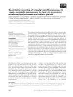
NOTE Figure 1 is included only as an aid to explaining the terminology used in this International Standard. The
components indicated in broken and dotted lines are covered by other technical specifications such as ETAG 002 or
standards concerned with curtain wall faỗades.
3.1
structural sealant glazing
SSG
assembly in which glass products are fixed to the structural seal frame by means of a sealant that has been
shown to be capable of withstanding the load actions applied to the glass products of the structural seal frame
3.2
anchorage
anchorage of the structural seal support frame on the framework
NOTE See (1) in Figure 1.
3.3
backer rod
pre-formed continuous strip that limits the section and height of a fillet of weather sealant
NOTE See (2) in Figure 1.
3.4
hermetic seal bite
dimension of the second barrier of the hermetic seal measured parallel to the glass unit at the panel level
NOTE See (3) in Figure 1.
3.5
faỗade framework
members to which the structural seal support frame is connected and which transmit the loads to the building
NOTE See (4) in Figure 1.
2 © ISO 2011 – All rights reserved
ISO 28728-1:2011(E)
Key 8 self-weight mechanical support
1 anchorage 9 weather seal
2 backer rod 10 setting blocks
3 height of the outer seal 11 adhesive spacer
4 faỗade framework 12 structural seal
5 finishing material 13 structural seal adhesion surface
6 hermetic seal 14 structural seal support frame
15 anti-adhesive film
6a (inner seal) 16 retaining device
6b (outer seal)
6c outer seal adhesion surface Figure 1 — Terminology
7 glass unit
© ISO 2011 – All rights reserved 3
ISO 28728-1:2011(E)
3.6
finishing material
elastomeric sealant extruded into the joint, of sufficient cross-section as to constitute a barrier to air and water
when cured, or a pre-extruded gasket with a fin of sufficient cross-section
NOTE See (5) in Figure 1 and (4) in Figure 3.
3.7
outer seal
sealant intended to ensure a hermetic seal, providing a barrier to water and vapour penetration, and light,
around the edge of an insulating unit whilst remaining compliant with displacements caused by wind or other
loads
NOTE 1 The hermetic seal is called “structural” (see 3.14) when it also has the supplementary function of adequately
transmitting to the seal support frame the forces applied to the glass.
NOTE 2 See (6b) in Figure 1 and (3) in Figure 3.
3.8
glass unit
element consisting of a single glass pane (monolithic or laminated) or an insulating glass unit (IGU) specified
for use in SSG
NOTE 1 The IGU may be one of two types: a unit with aligned edges for which the two panes have the same nominal
dimensions, or a unit with stepped edges for which the two panes have different dimensions.
NOTE 2 See Figure 2 and (7) in Figure 1.
3.9
insulating glass unit
IGU
pre-assembled unit comprising panes of glass that are sealed at the edges and separated by dehydrated
space(s), intended for use in buildings
3.10
self-weight mechanical support
element situated beneath the bottom edge of the glass unit that transmits the weight of the latter to the
structural seal support frame
NOTE See (8) in Figure 1.
3.11
weather seal
fillet of sealant or weather fin of adequate cross-section constituting a barrier to air and water
NOTE See (9) in Figure 1.
3.12
setting blocks
bearing elements situated between the self-weight mechanical support and the bottom edge of a glass unit
used to position the glass unit in the structural seal support frame and to avoid a permanent shear load
NOTE See (10) in Figure 1.
3.13
adhesive spacer
continuous pre-formed strip defining the cross-section of the fillet of sealant and used to align the glass
relative to the structural seal support frame
NOTE See (11) in Figure 1.
4 © ISO 2011 – All rights reserved
ISO 28728-1:2011(E)
3.14
structural seal
joint of elastic structural sealant extruded between glass element or glass and framework which is, when
cured, of adequate transverse cross-section as to transfer appropriate forces applied on the glass to the
structural seal support frame
NOTE See (12) in Figure 1 and (5) in Figure 3.
3.15
structural seal adhesion surface
continuous surface of the glass or structural seal support frame to which the structural sealant bonds
NOTE See (13) in Figure 1 and (6) in Figure 3.
3.16
structural seal support frame
metallic element to which the glass product is bonded
NOTE See (14) in Figure 1.
3.17
anti-adhesive film
film at the interface between two materials, used to prevent them bonding together
NOTE See (15) in Figure 1.
3.18
retaining device
piece intended to hold the glass product in place and therefore reduce any danger that may result in the event
of a structural seal failure
NOTE See (16) in Figure 1.
3.19
cohesive failure
cohesive rupture
rupture in a body of the sealant
3.20
adhesive failure
adhesive rupture
rupture at the interface between the sealant and the substrate
3.21
initial cure
stage in the curing where the sealant has appropriate cohesive strength to resist different levels of action
3.22
creep factor
shear design stress under permanent static load
3.23
initial type testing
determination of the performance of a product (characteristics, durability), on the basis of either actual tests or
other procedures
NOTE Other procedures include conventional, standardized, tabulated or generally accepted values, standardized or
recognized calculation methods, and test reports when made available, in accordance with this International Standard.
© ISO 2011 – All rights reserved 5
ISO 28728-1:2011(E)
3.24
test report
document that covers the results of tests undertaken on a representative sample of the product from
production or on a prototype design of the product
3.25
product description
document that details the relevant parameters for defining a product that complies with its relevant standard
NOTE It includes specific reference(s) to characteristics that are modified by the production process and by raw
materials.
3.26
significant change
variation in performance beyond the permitted tolerance for the characteristic
4 Symbols
a length of the smaller dimension of the glass m
Ag glass area m2
b breadth of IGU air space mm
bw width of the bead mm
c height of sealant necessary for structural purposes: c (0,5p.a) /( mm
ei initial glass thickness per test piece for Lo mm
Eo modulus (tangent or secant) kPa
F relevant combined load for wind, snow and self-weight Pa
Fs shear force Pa
Ft,i tensile loading Pa
Fmean average breaking force Pa
h height of structural sealant mm
ho height of sealant as specified in ISO 20492-2 mm
hu height of the outer seal of the unsupported IGU mm
Ko tangent stiffness at the origin kPa
Ksec rigidity modulus/secant stiffness kPa
Kx stiffness of the sample at x % elongation in the initial state kPa
Ky stiffness of the sample at y % elongation after conditioning kPa
L length of the loaded test piece mm
Lo initial length of the test piece mm
ls vertical length of the outer seal mm
lb length of the bead mm
m number of observations per test piece —
n number of test pieces per test for the temperature concerned —
p relevant combined load of the wind, snow, climatic effects and self-weight kPa
Pu weight of the unsupported IGU kPa
6 © ISO 2011 – All rights reserved
ISO 28728-1:2011(E)
Rdes design resistance kPa
Ru,5 characteristic force giving 75 % confidence that 95 % of the test results will be higher than kPa
this
r distance between structural seal and glass edge mm
ro step between both glass components mm
s standard deviation of the series —
smin minimum dimension of glass m
smax maximum dimension of glass m
t1 minimum glass thickness of the outermost component of an IGU mm
minimum glass thickness of the innermost component of an IGU mm
t2 time —
displacement under compression mm
t displacement under tension or compression mm
uc width of structural sealant mm
uij breaking stress kPa
w value of the breaking stress of test piece i, either under tension or shear kPa
X average breaking stress, either under tension or shear kPa
Xi average breaking stress, either under tension or shear, in the initial state kPa
x average breaking stress, either under tension or shear, after conditioning or ageing kPa
x o average tear breaking strength kPa
x c maximum difference in altitude between production transport and assembly at site m
x tear allowable stress of the sealant MPa
H coefficient depending on relative thickness of insulating glass panes —
shear stress kPa
eccentricity of 5 % with 75 % confidence —
shear design stress value declared by the sealant manufacturer kPa
shear design stress under dynamic load kPa
design stress kPa
tensile stress at the tensile displacement uij kPa
safety factor —
Γ∞
Γdes
des
ij
c
© ISO 2011 – All rights reserved 7
ISO 28728-1:2011(E)
5 Principle
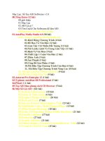
Key
1 retaining device
2 mechanical self-weight support
3 structural sealant support frame
Figure 2 — Schematic examples of the different types of SSG system
8 © ISO 2011 – All rights reserved
ISO 28728-1:2011(E)
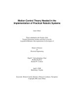
a) Situation 1
b) Situation 2
Key c) Situation 3
1 insulating glass unit
2 inner seal 9 adhesive spacer
3 outer seal 10 structural seal support frame
4 finishing material 11 laminated or monolithic glass
5 structural seal F1 face 1
6 structural seal adhesion surface F2 face 2
7 weather seal F3 face 3
8 setting block F4 face 4
NOTE The section drawings above are examples of structural sealant glazing system types II and IV.
Figure 3 — Principle
© ISO 2011 – All rights reserved 9
ISO 28728-1:2011(E)
SITUATION 1
The SSG seal is applied on face 2 of the insulating glass unit (IGU). The outer IGU sealant has no structural
function and therefore only contributes to the resistance of the unit against the ingress of water (vapour and
liquid), and air. Depending on the type and construction of the IGU sealant, any leakage of gas from the unit
will be minimised. The SSG seal must have good adhesion to the glass and steel surfaces to withstand the
mechanical stresses that result from the exposure of the IGU to the climatic elements and in particular the
effects of solar radiation.
SITUATION 2
The SSG seal is applied on face 4 of the IGU. The outer IGU sealant has a structural function as well as
having to maintain the integrity and performance of the IGU. Any stress or loads applied to the outer glass will
be transferred to the IGU sealant.
SITUATION 3
The SSG seal is applied on face 2 of the laminated or monolithic glass unit. The sealant has a structural
function and any loads applied to the glass will be transferred to it.
6 Required characteristics of glass products
6.1 Appropriate glass products
This part of ISO 28278 only allows the use of the following glass products.
6.1.1 Float glass
Until an ISO standard is published, the following standards may apply:
EN 572-2;
JIS R 3202;
ASTM C 1036.
6.1.2 Polished wired glass
Until an ISO standard is published, the following standards may apply:
EN 572-3;
JIS R 3204.
6.1.3 Drawn sheet glass
Until an ISO standard is published, the following standard may apply:
EN 572-4.
6.1.4 Patterned glass
Until an ISO standard is published, the following standards may apply:
EN 572-5;
JIS R 3203.
10 © ISO 2011 – All rights reserved
ISO 28728-1:2011(E)
6.1.5 Coated glass
The following standards may apply:
EN 1096;
ASTM C 1376;
JIS R 3221.
6.1.6 IGU
Until ISO 20492 (all parts) is published, the following standards may apply:
EN 1279;
ASTM E 2190;
ASTM C 1249;
JIS R 3209.
6.1.7 Heat strengthened soda lime silicate glass
The following standards may apply:
EN 1863;
ASTM C 1048;
JIS R 3222.
6.1.8 Thermally toughened soda lime silicate safety glass
The following standards may apply:
EN 12150;
ASTM C 1048;
JIS R 3206.
6.1.9 Heat soak tested thermally toughened soda lime silicate safety glass
The following standard may apply:
EN 14179.
6.1.10 Laminated glass and laminated safety glass
The following standard may apply:
ISO 12543 (all parts).
6.2 Dimensional tolerances
The tolerances for the different glass products can be found in the appropriate glass standards listed in 6.1.
© ISO 2011 – All rights reserved 11
ISO 28728-1:2011(E)
6.2.1 Glass shapes — Curved glass
Curved glass shall be considered to be flat for the purposes of calculating the products of the IGU seals and
glass thickness if the height of the glass at the centre of curve is 1/100 of the length of the curved side.
6.3 Corners, notches and holes
For annealed glass, corners [Figure 4 a)], notches [Figure 4 b)] and holes [Figure 4 c)] for annealed glass are
not considered in this part of ISO 28278.
a) b) c)
Figure 4 — Corner, notch and hole
For toughened and heat strengthened glass, corners [Figure 4 a)], notches [Figure 4 b)] and holes
[Figure 4 c)] are described in the following standards:
EN 1863;
EN 12150;
EN 14179.
In the case of IGUs, any angles cut in the glass forming the corner of the IGU shall not be less than 15°
(Figure 5).
Dimensions in millimetres
Figure 5 — Angle of IGUs
12 © ISO 2011 – All rights reserved
ISO 28728-1:2011(E)
7 Verification of the suitability of glass products for use in SSG systems when
exposed to ultraviolet (UV) radiation
7.1 General
The conformance of the glass product is determined by its capacity to resist the stresses specified in this
clause and by fulfilling the requirements regarding mechanical resistance and stability, reaction and resistance
to fire, hygiene, health, environment, safety, protection against noise, energy economy and heat retention, and
durability as a function of the situation and of the type of glass (see Scope).
7.2 IGU
ASTM C 1401-02, 22.5 may apply.
7.2.1 Situation 1 (see Figure 3)
In Situation 1 the outer seal of the IGU has no structural seal function.
Regarding the IGU itself:
Suitability for use of the IGU is determined in accordance with ISO 20492 (all parts). However, the
requirements of ISO 20492-4 should be amended as follows.
Outer seal:
a) The assessment tests of ISO 20492-4 should be amended as follows:
1) Exposure to heat: test conditions of ISO 20492-4 should be replaced by those in B.2.3.3, class T3
100 °C.
2) Exposure to UV: test conditions of ISO 20492-4 should be replaced by the Exposure to UV test and
specifications as defined in Annex F and B.2.7 of this part of ISO 28278.
or
b) The test methods and specifications of B.2.2, B.2.3 and B.2.4 of this part of ISO 28278 are applicable.
or
c) A structural sealant as defined in ISO 28278-2 can be used for the outer seal of the IGU in Situation 1,
Figure 3.
The test report of ISO 20492 should be amended accordingly.
7.2.2 Situation 2 (see Figure 3)
The outer seal of the IGU has a structural function and shall satisfy the following:
a) Suitability for use of the IGU is determined in accordance with ISO 20492.
b) The outer seal of the IGU shall satisfy the test methods and specifications of B.2.2, B.2.3 and B.2.4 of this
International Standard.
c) The test report in ISO 20492-4, D.6 should be amended accordingly.
EN 1279-4, D.6 may apply.
© ISO 2011 – All rights reserved 13
ISO 28728-1:2011(E)
7.2.3 Coated glass
7.2.3.1 Adhesion of coatings to glass surfaces and adhesion of coatings to interlayer used for
laminated glass products
The adhesion of coatings to glass surfaces and adhesion of coatings to the interlayer used for laminating
glass products should be performed in conformity with Annex D of ISO 20492-4:2010. In the case of the outer
seal, it should be amended as follows:
7.2.3.1.1 Bonding — Outer seal without structural function
Assessment tests in conformity with Annex D and Clause 6 of ISO 20492-4 shall be carried out but amended
as follows:
a) Heat exposure test, 5.1.3.2 of ISO 20492-4 performed in conformity with B.2.3.3, class T3 100 °C.
1) UV exposure test, 5.1.3.4 of ISO 20492-4 performed in conformity with B.2.7.
2) The test report referred to in ISO 20492-4, D.6 should be amended accordingly.
or
b) The tests methods and specifications of B.2.2, B.2.3 and B.2.4 of this International Standard are
applicable.
The test report referred to in ISO 20492-4, D.6, should be amended accordingly.
EN 1279-4:2003, D.6 may apply.
7.2.3.1.2 Bonding — Outer seal with structural function
Assessment tests in conformity with B.2.2, B.2.3 (only apply if not performed on clear glass) and B.2.4 of this
part of ISO 28278 shall be carried out.
Provided the structural sealant is specifically developed and recommended by the sealant manufacturer for
use in this application, the test report referred to in ISO 20492-4:2010 should be amended accordingly.
Annex D of EN 1279-4 may also apply.
7.2.3.2 Substitution of the coated glass when the coating at the edge does not require removal
First, proceed in accordance with 5.2.3 of ISO 20492-4:2010, but then carry out assessment tests in
accordance with Annex D and Clause 5 amended as follows:
Heat exposure test, 5.1.3.2 of ISO 20492-4:2010 (5.1.3.2 of EN 1279-4:2003) performed in conformity
with Annex B of this part of ISO 28278.
UV exposure test, 5.1.3.4 of ISO 20492-4, performed in conformity with Annex B of this part of ISO 28278.
Subclauses 4.2.3 and 5.1.3.4 of EN 1279-4:2003 may also apply.
The rules of extrapolation in EN 1096-2, Annex F are also applicable.
7.2.4 Possibility of substituting the outer IGU seal
First, proceed in accordance with 5.2.2 of ISO 20492-4:2010.
Subclause 4.2.2 of EN 1279-4:2003 may also apply.
14 © ISO 2011 – All rights reserved
ISO 28728-1:2011(E)
Then, produce a test report that takes into account the performance of the outer seal versus its functional
requirements regarding UV resistance only or UV resistance and/or structural function in conformity with B.2.2,
B.2.3 and B.2.4 of this part of ISO 28278.
7.2.5 Further requirements for the outer IGU seal when in an unsupported case
In addition to the requirements specified in 7.2.1 to 7.2.4, the outer seal shall meet the following
supplementary requirement:
the mechanical properties of the outer seal shall comply with the specification corresponding to Creep
Grade C1 of B.2.3.8 of this part of ISO 28278 (Displacement under permanent load).
7.2.6 Case for a faỗade glazed between 0 and 30 from the vertical (towards the outside) and
between 0° and 7° from the horizontal
The requirements described in 7.2.5 are applicable.
7.3 Laminated glass or monolithic glass — Situation 3 (see Figure 3)
The monolithic glass shall comply with 6.1.1.
The laminated glass or laminated safety glass shall comply with the definition of laminated glass or laminated
safety glass according to 6.1.10.
Each component of the laminated glass shall be supported.
7.4 Assessment of the adhesion between the sealant and the glass
7.4.1 Float glass
When the tests according to B.2.3 and B.2.4 required by this part of ISO 28278 are performed on float glass in
accordance with 6.1.1, the adherence between glass and structural sealant can be extrapolated to the
following glass types:
heat strengthened soda lime silicate glass conforming with 6.1.7;
thermally toughened soda lime silicate safety glass conforming with 6.1.8 or 6.1.9, except enamelled
glass (see 7.4.3).
7.4.2 Coated glass
When tests according to B.2.3 and B.2.4 of this part of ISO 28728 are performed on one of the following glass
substrates that have been coated, the adhesion between coated glass and structural sealant can be
extrapolated for the rest of the glass substrates in this list:
basic soda lime silicate glass products conforming with 6.1.1;
heat strengthened soda lime silicate glass conforming with 6.1.7;
thermally toughened soda lime silicate safety glass conforming with 6.1.8 or 6.1.9.
NOTE When the tests in B.2.3 and B.2.4 are performed on one identified coating, the test can apply to other coatings
in accordance with Annex F of EN 1096-2.
© ISO 2011 – All rights reserved 15
ISO 28728-1:2011(E)
7.4.3 Enamelled glass
When the tests according to B.2.3 and B.2.4 are performed for one delivery, the dynamic tensile/peel test on
structural sealant in Annex A of ISO 28278-2:2010 is required in order to extrapolate the assessment of the
adhesion to other deliveries.
NOTE See 22.4 Spandrel of ASTM C 1401-02.
7.4.4 Patterned glass
When the tests according to B.2.3 and B.2.4 are performed for one type of patterned glass, the dynamic
tensile/peel test on structural sealant in Annex A of ISO 28278-2:2010 is required in order to extrapolate the
assessment of the adhesion to other deliveries.
8 Design
8.1 Calculation of the thickness of the glass
The thickness of the glass is calculated in accordance with national regulations.
The glass product (thickness and types of glass components) shall ensure the resistance against wind, snow,
permanent load, and other mechanical, (quasi-)static action.
The current method of determining mechanical resistance in the country of destination shall be applied, as
long as no International Standard is applicable for the design of the construction or building site concerned.
8.2 Calculation of the height of the outer sealant of the IGU for supported and unsupported
glazing
8.2.1 Supported IGU
8.2.1.1 Flush edge unit
The outer seal of the IGU has a structural function (see Figure 6).
The height, h, of the outer seal is given by Equation (1):
h c 0,5 F smin (1)
NOTE Minimum 6 mm.
where
h is the height of the outer seal barrier (mm);
c is the height of sealant necessary for structural purposes: c (0,5 p.a) /( (mm);
is the allowable stress of the sealant (MPa);
is the coefficient depending on the relative thickness of the components (Figure 7);
smin is minimum dimension of glass, (mm).
16 © ISO 2011 – All rights reserved