ISO/IEC TS 29125:2017Amd 1:2020 Information technology — Telecommunications cabling requirements for remote powering of terminal equipment — Amendment 1
Bạn đang xem bản rút gọn của tài liệu. Xem và tải ngay bản đầy đủ của tài liệu tại đây (1.28 MB, 16 trang )
ISO/IEC TS 29125
Edition 1.0 2020-05
TECHNICAL
SPECIFICATION
AMENDMENT 1
Information technology – Telecommunications cabling requirements for remote
powering of terminal equipment
ISO/IEC TS 29125:2017-04/AMD1:2020-05(en)
THIS PUBLICATION IS COPYRIGHT PROTECTED
Copyright © 2020 ISO/IEC, Geneva, Switzerland
All rights reserved. Unless otherwise specified, no part of this publication may be reproduced or utilized in any form
or by any means, electronic or mechanical, including photocopying and microfilm, without permission in writing from
either IEC or IEC's member National Committee in the country of the requester. If you have any questions about
ISO/IEC copyright or have an enquiry about obtaining additional rights to this publication, please contact the address
below or your local IEC member National Committee for further information.
IEC Central Office Tel.: +41 22 919 02 11
3, rue de Varembé
CH-1211 Geneva 20 www.iec.ch
Switzerland
About the IEC
The International Electrotechnical Commission (IEC) is the leading global organization that prepares and publishes
International Standards for all electrical, electronic and related technologies.
About IEC publications
The technical content of IEC publications is kept under constant review by the IEC. Please make sure that you have the
latest edition, a corrigendum or an amendment might have been published.
IEC publications search - webstore.iec.ch/advsearchform Electropedia - www.electropedia.org
The advanced search enables to find IEC publications by a The world's leading online dictionary on electrotechnology,
variety of criteria (reference number, text, technical containing more than 22 000 terminological entries in English
committee,…). It also gives information on projects, replaced and French, with equivalent terms in 16 additional languages.
and withdrawn publications. Also known as the International Electrotechnical Vocabulary
(IEV) online.
IEC Just Published - webstore.iec.ch/justpublished
Stay up to date on all new IEC publications. Just Published IEC Glossary - std.iec.ch/glossary
details all new publications released. Available online and 67 000 electrotechnical terminology entries in English and
once a month by email. French extracted from the Terms and definitions clause of
IEC publications issued between 2002 and 2015. Some
IEC Customer Service Centre - webstore.iec.ch/csc entries have been collected from earlier publications of IEC
If you wish to give us your feedback on this publication or TC 37, 77, 86 and CISPR.
need further assistance, please contact the Customer Service
Centre:
ISO/IEC TS 29125
Edition 1.0 2020-05
TECHNICAL
SPECIFICATION
AMENDMENT 1
Information technology – Telecommunications cabling requirements for remote
powering of terminal equipment
INTERNATIONAL ISBN 978-2-8322-8310-3
ELECTROTECHNICAL
COMMISSION
ICS 35.200
Warning! Make sure that you obtained this publication from an authorized distributor.
– 2 – ISO/IEC TS 29125:2017/AMD1:2020
© ISO/IEC 2020
FOREWORD
This amendment has been prepared by subcommittee 25: Interconnection of information
technology equipment, of ISO/IEC joint technical committee 1: Information technology.
The text of this amendment is based on the following documents:
DTS Report on voting
JTC1-SC25/2919/DTS JTC1-SC25/2945/RVDTS
Full information on the voting for the approval of this amendment can be found in the report
on voting indicated in the above table.
_____________
INTRODUCTION to the amendment
This amendment incorporates changes necessary to include remote powering using single
pair cabling.
Introduction
Add the following at end of the last paragraph:
This document addresses the use of generic balanced single pair cabling for customer
premises, to be specified in future amendments of the ISO/IEC 11801 series, for remote
powering of terminal equipment. This document uses measurements and empirical models to
estimate the thermal performance of single pair cable bundles of various conductor diameters.
1 Scope
Replace list item a) with the following:
a) addresses the support of safety extra low voltage (SELV) and limited power source (LPS)
applications that provide remote power over:
• 4-pair balanced cabling in accordance with the reference implementations of
ISO/IEC 11801 series standards using currents per conductor of up to 500 mA;
• 1-pair balanced cabling using currents per conductor of up to 1 000 mA;
and targets the support of applications that provide remote power over balanced cabling to
terminal equipment,
5 Cabling selection and performance
Replace the first paragraph with the following:
Cabling for remote powering can be implemented using 4-pair and 1-pair balanced cabling.
ISO/IEC TS 29125:2017/AMD1:2020 – 3 –
© ISO/IEC 2020
6.3 Temperature rise and current capacity
Add the following new paragraph after the third paragraph:
The maximum current per conductor for different temperature rise in a bundle of 37 cables of
1-pair cables with 0,57 mm diameter conductors, and 37 cords of 1-pair 0,40 mm cords with
all pairs energized is shown in Table 5.
Replace the fourth paragraph with the following new paragraph:
Annex B provides an engineering model that may be used for specific cable types, cable
constructions, and installation conditions to derive the bundle size for a particular current per
conductor. Clause B.7 describes a simplified version of the engineering model in Annex B and
was used to derive the worst case values in Tables 1 to 9 based on constants calculated from
measurements of typical cables for each cable category or conductor diameter. The
measurement procedures used to determine the constants are detailed in Annex F.
Replace the Table 1 title with the following new title:
Table 1 – Maximum current per conductor versus temperature
rise in a 37 4-pair cable bundle in air and conduit
Add the following new Table 5 after Table 1:
Table 5 – Maximum current per conductor versus temperature rise
in a 37 1-pair cable bundle in air and conduit
Temperature rise Current per conductor 0,57 mm diameter Current per conductor 0,40 mm cords
°C
mA mA
5
7,5 air conduit air conduit
10
12,5 866 738 608 518
15
17,5 1 061 904 744 634
20
1 225 1 044 860 732
1 370 1 167 961 819
1 501 1 278 1 053 897
1 621 1 381 1 137 969
1 733 1 476 1 216 1 036
Temperature rise above 10 °C shown in grey background is not recommended.
NOTE These values are based on conductor temperature measurement of typical cables and cords.
Replace the fifth paragraph with the following new paragraph:
Table 2 shows current capacity for different categories of 4-pair cable, independent of
construction, for a given temperature rise. Table 6 shows current capacity for 1-pair cables of
conductor diameters of cable, independent of construction, for a given temperature rise.
– 4 – ISO/IEC TS 29125:2017/AMD1:2020
Add the following new Table 6 after Table 2: © ISO/IEC 2020
Table 6 – Calculated worst case current per conductor versus temperature
rise in a bundle of 37 1-pair cables of different conductor diameters in air and conduit
0,32 mm 0,40 mm 0,51 mm 0,57 mm 0,65 mm 0,81 mm 1,02 mm
diameter diameter diameter diameter diameter diameter diameter
ΔT mA mA mA mA mA mA mA
°C air conduit air conduit air conduit air conduit air conduit air conduit air conduit
2 307 262 384 327 490 417 548 466 624 532 779 663 981 835
4 435 370 543 463 693 590 775 660 883 753 1 101 938 1 387 1 181
6 533 454 666 567 849 723 949 808 1 082 922 1 349 1 149 1 699 1 446
8 615 524 769 655 981 835 1 096 933 1 249 1 065 1 558 1 327 1 962 1 670
10 688 586 860 732 1 096 934 1 225 1 044 1 397 1 190 1 742 1 484 2 194 1 867
12 753 642 942 802 1 201 1 023 1 342 1 143 1 530 1 304 1 908 1 625 2 403 2 046
14 814 693 1 017 867 1 297 1 105 1 450 1 235 1 653 1 409 2 061 1 755 2 596 2 210
16 870 741 1 087 926 1 387 1 181 1 550 1 320 1 767 1 506 2 203 1 877 2 775 2 362
18 923 786 1 153 983 1 471 1 253 1 644 1 400 1 874 1 597 2 337 1 991 2 943 2 506
20 973 829 1 216 1 036 1 551 1 321 1 733 1 476 1 976 1 684 2 463 2 098 3 102 2 641
Temperature rise above 10 °C shown in grey background is not recommended.
The values in this table are based on the implicit DC resistance derived from the insertion loss of the various
conductor diameters of cable. Manufacturers' and/or suppliers' specifications give information relating to a
specific cable.
NOTE The current per conductor for each 1-pair cable is also dependent on the cable construction.
6.4.3 Cable count within a bundle
Replace the first paragraph with the following new paragraphs:
This document uses 37-cable bundles as the basis for developing the temperature rise and
current per conductor with all pairs energized. For other cases (e.g. where bundle count
exceeds 37 cables), the guidelines provided in 6.4 can be used.
Refer to Table 3 to determine the maximum temperature rise using 500 mA per conductor for
4-pair cable bundles of different count.
Refer to Table 7 to determine the maximum temperature rise using 1 000 mA per conductor
for 1-pair cable bundles of different count.
ISO/IEC TS 29125:2017/AMD1:2020 – 5 –
© ISO/IEC 2020
Replace the Table 3 title with the following new title:
Table 3 – Temperature rise versus 4-pair cable bundle size (500 mA per conductor)
Add the following new Table 7 after Table 3:
Table 7 – Temperature rise versus 1-pair cable bundle size
(1 000 mA per conductor)
Temperature rise
°C
Number 0,32 mm 0,40 mm 0,51 mm 0,57 mm 0,65 mm 0,81 mm 1,02 mm
of cables diameter diameter diameter diameter diameter diameter diameter
mA mA mA mA mA mA mA
air conduit air conduit air conduit air conduit air conduit air conduit air conduit
1 2,9 4,4 1,9 2,8 1,1 1,7 0,9 1,4 0,7 1,1 0,5 0,7 0,3 0,4
7 8,2 11,9 5,2 7,6 3,2 4,7 2,6 3,8 2,0 2,9 1,3 1,9 0,8 1,2
19 14,3 20,2 9,2 12,9 5,6 8,0 4,5 6,4 3,5 4,9 2,2 3,2 1,4 2,0
24 16,4 23,0 10,5 14,7 6,4 9,0 5,2 7,2 4,0 5,6 2,6 3,6 1,6 2,3
37 21,1 29,1 13,5 18,6 8,3 11,5 6,7 9,2 5,1 7,1 3,3 4,5 2,1 2,9
48 24,7 33,6 15,8 21,5 9,7 13,2 7,8 10,6 6,0 8,1 3,9 5,2 2,4 3,3
52 25,9 35,2 16,6 22,5 10,2 13,8 8,2 11,1 6,3 8,5 4,0 5,5 2,5 3,5
61 28,6 38,5 18,3 24,6 11,3 15,1 9,0 12,1 6,9 9,3 4,5 6,0 2,8 3,8
64 29,4 39,5 18,8 25,3 11,6 15,6 9,3 12,5 7,1 9,6 4,6 6,2 2,9 3,9
74 32,2 42,9 20,6 27,5 12,7 16,9 10,2 13,5 7,8 10,4 5,0 6,7 3,2 4,2
91 36,7 48,4 23,5 31,0 14,5 19,0 11,6 15,2 8,9 11.7 5,7 7,5 3,6 4,8
Temperature rise above 10 °C shown in grey background is not recommended.
The values in this table are based on the implicit DC resistance of the various conductor diameters of cable.
Manufacturers' and/or suppliers' specifications give information relating to a specific cable.
NOTE 1 The temperature rise (°C) is based upon a current of 1 000 mA per conductor, for all cables in the
bundle.
NOTE 2 The current per conductor for each conductor diameter is also dependent on the cable construction.
6.4.4 Reducing temperature increase
Replace the first dashed item with the following:
– using higher category cable (for 4-pair cables),
Replace the fifth paragraph ("Table 4 shows …") with the following new paragraphs:
Table 4 shows the effect of energizing the number of pairs within a 37-cable bundle for
different 4-pair cable categories.
Table 8 shows the effect of energizing the number of pairs within a 37-cable bundle for
different 1-pair cable constructions in air. Figure 1 shows this data in graphical form.
Table 9 shows the effect of energizing the number of pairs within a 37-cable bundle for
different 1-pair cable constructions in conduit. Figure 2 shows this data in graphical form.
In the sixth paragraph, replace: "cable bundles" with "4-pair cable bundles".
– 6 – ISO/IEC TS 29125:2017/AMD1:2020
Replace the Table 4 title with the following new title: © ISO/IEC 2020
Table 4 – Temperature rise for a type of 4-pair cable versus the number of energized
pairs in a 37-cable bundle (500 mA per conductor)
Add the following new Table 8 after Table 4:
Table 8 – Temperature rise for a 0,57 mm conductor diameter
1-pair cable versus current for different bundle sizes in air
Bundle size 200 400 ΔT (°C) 800 1 000
0,103 0,413 Current (mA) 1,653 2,582
7 0,18 0,722 2,887 4,511
19 0,266 1,065 600 4,26 6,656
37 0,36 1,442 0,93 5,767 9,01
61 0,463 1,852 1,624 7,407 11,573
91 2,396
3,244
4,166
Temperature rise above 10 °C shown in grey background is not recommended.
The values in this table are based on the DC resistance of the cable conductors. Manufacturers' and/or
suppliers' specifications give information relating to a specific cable.
NOTE The temperature rise for a particular cable is also dependent on the cable construction.
Insert the following new Figure 3 after Table 8:
Figure 3 – Temperature rise for a 0,57 mm conductor diameter
1-pair cable versus current for different bundle sizes in air
ISO/IEC TS 29125:2017/AMD1:2020 – 7 –
© ISO/IEC 2020
Insert the following new Table 9 after Figure 3:
Table 9 – Temperature rise for a 0,57 mm conductor diameter
1-pair cable versus current for different bundle sizes in conduit
Bundle size 200 400 ΔT (°C) 800 1 000
0,15 0,6 Current (mA) 2,401 3,752
7 0,255 1,02 4,081 6,376
19 0,367 1,467 600 5,87 9,171
37 0,485 1,941 1,351 7,762 12,128
61 0,61 2,439 2,295 9,756 15,244
91 3,302
4,366
5,488
Temperature rise above 10 °C shown in grey background is not recommended.
The values in this table are based on the DC resistance of the cable conductors. Manufacturers' and/or
suppliers' specifications give information relating to a specific cable.
NOTE The temperature rise for a particular cable is also dependent on the cable construction.
Insert the following new Figure 4 after Table 9:
Figure 4 – Temperature rise for a 0,57 mm conductor diameter
1-pair cable versus current for different bundle sizes in conduit
7 Remote power delivery over balanced cabling
Add the following new subclause title before the first paragraph:
7.1 4-pair balanced cabling
Add the following new subclause after the last paragraph:
– 8 – ISO/IEC TS 29125:2017/AMD1:2020
© ISO/IEC 2020
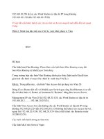
7.2 1-pair balanced cabling
Figure 5 shows examples of specified transmission paths used in 1-pair balanced cabling.
The channel is the transmission path between equipment such as a LAN switch or hub and
the terminal equipment. The channel does not include the connections at the data source
equipment and the terminal equipment. The channel, the permanent link or the CP link shall
meet the transmission requirements specified in the design standards.
Remote power may be provided to terminal equipment via balanced cabling equipment
interfaces. Remote power is introduced to the balanced cabling channel at the Floor
Distributor using the phantom circuit of data pairs from the power sourcing equipment, as
shown in Figure 5.
Figure 5 – Single pair remote powering using signal pairs
When mid-span power source equipment replaces a generic balanced cabling component or
components, the data pair shall meet the performance requirements of the component or
components it replaces (e.g. patch cord, patch panel or combination thereof), regardless of
the equipment interfaces used for input and output connections.
8 Connecting hardware
Add the following new subclause title before the first paragraph:
8.1 General
Add the following new subclause title after the sixth paragraph:
8.2 4-pair balanced cabling
Move the first paragraph in 8.1 to become the first paragraph in 8.2.
Add the following new subclause after the NOTE:
8.3 1-pair balanced cabling
Contacts need to support 2,0 A for mating and un-mating under load.
Connecting hardware in channels used to support remote power applications shall have an
appropriate current rating when mated. Connecting hardware contacts may deteriorate as a
result of mating or un-mating under electrical load, leading to possible degradation of
transmission characteristics (IEC 60512-99-002). Manufacturers should be consulted
regarding the number of mating and un-mating cycles supported by connecting hardware
while conveying the intended levels of electrical power.
NOTE A test schedule for engaging and separating connectors under electrical load is described in
IEC 60512-99-002.
ISO/IEC TS 29125:2017/AMD1:2020 – 9 –
© ISO/IEC 2020
B.10 Coefficients for air and conduit
Replace the first paragraph with the following new paragraphs:
Table B.1 shows the bundling coefficients determined from measurements for the different
4-pair cables and cords using at least two different bundle sizes (e.g. 37 and 61 cables per
bundle).
Table B.2 shows the resistance per metre and the bundling coefficients determined from
measurements for the different 1-pair cables and cords using at least two different bundle
sizes (e.g. 37 and 19 cables per bundle).
See Annex F for a recommended method to determine the constants for different types of
cables and cords.
Replace the Table B.1 title with the following new title:
Table B.1 – Bundling coefficients for different types of 4-pair cables
and cords (all 4 pairs energized) in air and conduit
Insert the following new Table B.2 after Table B.1:
Table B.2 – DC resistance and bundling coefficients for 1-pair cables of different
conductor diameters (all conductors energized) in air and conduit
Conductor diameter R Bundling coefficients
mm Ω/m in air in conduit
0,32 0,220 2
0,40 0,140 9 C1 C2 C1 C2
0,51 0,086 7 0,109 1 0,885 0,026 1 1,349
0,57 0,069 4 0,069 9
0,65 0,053 4 0,043 1,797 0,053 2,739
0,81 0,034 4 0,034 4
1,02 0,021 7 0,026 5 1,105 0,032 6 1,685
0,017
0,010 7 0,885 0,026 1 1,349
0,680 6 0,020 1 1,037
0,438 3 0,012 9 0,668
0,276 4 0,008 2 0,421 3
NOTE The bundling coefficients are directly proportional to the square of the ratio of the two conductor
diameters.
C.1 DC loop resistance
Add the following new subclause title before the first paragraph:
C.1.1 4-pair cabling
Add the following new subclause title and paragraphs before the second paragraph:
C.1.2 1-pair cabling
The DC loop resistance requirements of a 1-pair channel can be calculated using Table B.2
for DC resistance of 90 m of single pair cables, 10 m of single pair cords, and 4 connections
with 0,10 Ω per connection. For example, for a T1-B channel the maximum DC resistance is
typically 17 Ω.
– 10 – ISO/IEC TS 29125:2017/AMD1:2020
© ISO/IEC 2020
The DC loop resistance is dependent on the conductor diameter and length of the cabling.
Selecting a larger conductor diameter is one way to reduce DC loop resistance and improve
both energy consumption and heating. Careful attention to cable routing to minimize cable
lengths will substantially decrease DC loop resistance.
C.2 DC resistance unbalance (within pair)
Add the following new subclause title before the first paragraph:
C.2.1 General
Delete the first paragraph of C.2.1.
Add the following new subclause title and paragraph before Table C.2:
C.2.2 4-pair cabling
The DC resistance unbalance requirements of each pair of a cable, connector, or channel are
specified in ISO/IEC 11801-1. For convenience, Table C.2 shows those requirements as
shown in Formula (C.1).
Replace the Table C.2 title with the following new title:
Table C.2 – DC resistance unbalance of 4-pair cables,
connecting hardware and channels
Add the following new subclause after Table C.2:
C.2.3 1-pair cabling
The DC resistance unbalance requirements of each pair of a cable, connector, or channel are
expected to be similar to those of Category 5 components of Table C.2.
E.2 Test set-up
Replace the first paragraph with the following new paragraph:
All tests shall be undertaken on bundles containing 37 cables each having a nominally circular
cross-section. This quantity is used in order to produce a cable bundle with three complete
layers surrounding a centre cable as shown in Figure E.1.
Replace the third paragraph ("The cables are configured …") with the following new
paragraph:
The cables are configured to allow the balanced pair within them to be fed with a constant
current. The test shall be coupled with all conductors in series so the same current is flowing
through the whole set-up as shown in Figure E.3 for 4-pair cabling and Figure E.4 for 1-pair
cabling.
Replace the Figure E.3 title with the following new title:
Figure E.3 – 4-pair cabling conductor configuration
ISO/IEC TS 29125:2017/AMD1:2020 – 11 –
© ISO/IEC 2020
Insert the following new Figure E.4 after Figure E.3:
Figure E.4 – 1-pair cabling conductor configuration
F.1 General
Insert the following new paragraph at the end of Clause F.1:
The method applies to both 4-pair and 1-pair cabling although Figures F.1 to F.4 show 4-pair
implementations.
Bibliography
Add the following new reference after the second reference:
IEC 60512-99-002, Connectors for electrical and electronic equipment – Tests and
measurements – Part 99-002: Endurance test schedules – Test 99b: Test schedule for
unmating under electrical load
_____________
INTERNATIONAL
ELECTROTECHNICAL
COMMISSION
3, rue de Varembé
PO Box 131
CH-1211 Geneva 20
Switzerland
Tel: + 41 22 919 02 11
www.iec.ch