ISOIEC TS 29125:2017Amd 1:2020 Information technology — Telecommunications cabling requirements for remote powering of terminal equipment — Amendment 1
Bạn đang xem bản rút gọn của tài liệu. Xem và tải ngay bản đầy đủ của tài liệu tại đây (2.37 MB, 38 trang )
ISO/IEC TS 29125
Edition 2.0 2017-04
TECHNICAL
SPECIFICATION
colour
inside
Information technology – Telecommunications cabling requirements for remote
powering of terminal equipment
ISO/IEC TS 29125:2017-04(en)
THIS PUBLICATION IS COPYRIGHT PROTECTED
Copyright © 2017 ISO/IEC, Geneva, Switzerland
All rights reserved. Unless otherwise specified, no part of this publication may be reproduced or utilized in any form
or by any means, electronic or mechanical, including photocopying and microfilm, without permission in writing from
either IEC or IEC's member National Committee in the country of the requester. If you have any questions about
ISO/IEC copyright or have an enquiry about obtaining additional rights to this publication, please contact the address
below or your local IEC member National Committee for further information.
IEC Central Office Tel.: +41 22 919 02 11
3, rue de Varembé Fax: +41 22 919 03 00
CH-1211 Geneva 20
Switzerland www.iec.ch
About the IEC
The International Electrotechnical Commission (IEC) is the leading global organization that prepares and publishes
International Standards for all electrical, electronic and related technologies.
About IEC publications
The technical content of IEC publications is kept under constant review by the IEC. Please make sure that you have the
latest edition, a corrigenda or an amendment might have been published.
IEC Catalogue - webstore.iec.ch/catalogue Electropedia - www.electropedia.org
The stand-alone application for consulting the entire The world's leading online dictionary of electronic and
bibliographical information on IEC International Standards, electrical terms containing 20 000 terms and definitions in
Technical Specifications, Technical Reports and other English and French, with equivalent terms in 16 additional
documents. Available for PC, Mac OS, Android Tablets and languages. Also known as the International Electrotechnical
iPad. Vocabulary (IEV) online.
IEC publications search - www.iec.ch/searchpub IEC Glossary - std.iec.ch/glossary
The advanced search enables to find IEC publications by a 65 000 electrotechnical terminology entries in English and
variety of criteria (reference number, text, technical French extracted from the Terms and Definitions clause of
committee,…). It also gives information on projects, replaced IEC publications issued since 2002. Some entries have been
and withdrawn publications. collected from earlier publications of IEC TC 37, 77, 86 and
CISPR.
IEC Just Published - webstore.iec.ch/justpublished
Stay up to date on all new IEC publications. Just Published IEC Customer Service Centre - webstore.iec.ch/csc
details all new publications released. Available online and If you wish to give us your feedback on this publication or
also once a month by email. need further assistance, please contact the Customer Service
Centre:
ISO/IEC TS 29125
Edition 2.0 2017-04
TECHNICAL
SPECIFICATION
colour
inside
Information technology – Telecommunications cabling requirements for remote
powering of terminal equipment
INTERNATIONAL ISBN 978-2-8322-4223-0
ELECTROTECHNICAL
COMMISSION
ICS 35.200
Warning! Make sure that you obtained this publication from an authorized distributor.
– 2 – ISO/IEC TS 29125:2017 © ISO/IEC 2017
CONTENTS
FOREW ORD ........................................................................................................................... 4
INTRODUCTION ..................................................................................................................... 6
1 Scope ..............................................................................................................................7
2 Normative references ......................................................................................................7
3 Terms, definitions and abbreviated terms ........................................................................7
3.1 Terms and definitions..............................................................................................7
3.2 Abbreviated terms...................................................................................................8
4 Conformance ...................................................................................................................8
5 Cabling selection and performance ..................................................................................9
6 Installation conditions ......................................................................................................9
6.1 General...................................................................................................................9
6.2 Ambient temperature...............................................................................................9
6.3 Temperature rise and current capacity ....................................................................9
6.4 Factors affecting temperature increase .................................................................11
6.4.1 General ......................................................................................................... 11
6.4.2 Installation near equipment............................................................................11
6.4.3 Cable count within a bundle ........................................................................... 11
6.4.4 Reducing temperature increase .....................................................................12
6.4.5 Cable bundle suspended in air.......................................................................13
6.4.6 Administration................................................................................................ 14
7 Remote power delivery over balanced cabling ...............................................................14
8 Connecting hardware..................................................................................................... 15
Annex A (informative) Mitigation considerations for installed cabling....................................17
A.1 General................................................................................................................. 17
A.2 Minimum cabling class .......................................................................................... 17
A.3 Bundle size and location ....................................................................................... 17
A.4 Mitigation options.................................................................................................. 17
Annex B (informative) Modelling temperature rise for cable types, bundle sizes and
installation conditions .................................................................................................... 18
B.1 Model basics......................................................................................................... 18
B.2 Power dissipated (P) ............................................................................................. 18
B.3 Temperature difference from ambient temperature to bundle surface (∆Tu)...........19
B.3.1 Model equations ............................................................................................ 19
B.3.2 Typical values for constant ρu ....................................................................... 19
B.4 Temperature difference from bundle surface to bundle centre (∆Tth).....................19
B.4.1 Model equations ............................................................................................ 19
B.4.2 Typical values for constant ρth ...................................................................... 19
B.5 Temperature variation within the bundle (∆T(x)) ....................................................20
B.6 Alternative presentation of the model ....................................................................20
B.7 Adaptation model used to derive temperature rise vs. cables in a bundle ..............20
B.8 Calculations .......................................................................................................... 21
B.9 Example................................................................................................................ 21
B.10 Coefficients for air and conduit.............................................................................. 22
Annex C (informative) Transmission parameters related to remote powering........................23
C.1 DC loop resistance................................................................................................ 23
ISO/IEC TS 29125:2017 © ISO/IEC 2017 – 3 –
C.2 DC resistance unbalance (within pair) ................................................................... 23
C.3 DC resistance unbalance (pair to pair) ..................................................................24
Annex D (informative) Illustrations of heating of various bundle sizes and
configurations ................................................................................................................ 26
D.1 Limiting cable bundle size .....................................................................................26
D.2 Separating into smaller bundles ............................................................................27
Annex E (informative) Test protocol .....................................................................................28
E.1 Background........................................................................................................... 28
E.2 Test set-up ........................................................................................................... 28
Annex F (informative) Detailed test procedure .....................................................................30
F.1 General................................................................................................................. 30
F.2 Test set-up ........................................................................................................... 30
F.2.1 Thermocouple placement...............................................................................30
F.2.2 Measurement of cable bundle in air ...............................................................31
F.2.3 Measurement of cable bundle in conduit ........................................................32
Bibliography.......................................................................................................................... 34
Figure 1 – Examples of end point powering systems using signal pairs (top) and spare
pairs (bottom) ....................................................................................................................... 14
Figure 2 – Examples of mid-span powering systems ............................................................. 15
Figure B.1 – Temperature rise profile....................................................................................18
Figure D.1 – 91-cable bundle ................................................................................................ 26
Figure D.2 – Three bundles of 37 cables...............................................................................26
Figure D.3 – Three bundles of 37 cables with separation ......................................................27
Figure E.1 – 37-cable bundle and temperature location.........................................................28
Figure E.2 – "Perfect bundle" and thermocouple configuration ..............................................29
Figure E.3 – Conductor configuration .................................................................................... 29
Figure F.1 – Placement of thermocouple...............................................................................30
Figure F.2 – Securing of the thermocouple............................................................................31
Figure F.3 – Test set-up for cable bundles in air ...................................................................32
Figure F.4 – Test set-up for cable bundles in conduit ............................................................33
Table 1 – Maximum current per conductor versus temperature rise in a 37-cable
bundle in air and conduit (all 4 pairs energized) ....................................................................10
Table 2 – Calculated worst case current per conductor versus temperature rise in a
bundle of 37 4-pair cables (all pairs energized) ..................................................................... 11
Table 3 – Temperature rise versus cable bundle size (500 mA per conductor) ......................12
Table 4 – Temperature rise for a type of cable versus the number of energized pairs in
a 37-cable bundle (500 mA per conductor)............................................................................13
Table B.1 – Bundling coefficients for different types of cables and cords (all 4 pairs
energized) ............................................................................................................................ 22
Table C.1 – Maximum DC loop resistance of channels ..........................................................23
Table C.2 – DC resistance unbalance of cables, connecting hardware and channels ............24
Table C.3 – DC resistance unbalance (pair to pair) ...............................................................25
– 4 – ISO/IEC TS 29125:2017 © ISO/IEC 2017
INFORMATION TECHNOLOGY –
TELECOMMUNICATIONS CABLING REQUIREMENTS
FOR REMOTE POWERING OF TERMINAL EQUIPMENT
FOREWORD
1) ISO (the International Organization for Standardization) and IEC (the International Electrotechnical
Commission) form the specialized system for worldwide standardization. National bodies that are members of
ISO or IEC participate in the development of International Standards through technical committees established
by the respective organization to deal with particular fields of technical activity. ISO and IEC technical
committees collaborate in fields of mutual interest. Other international organizations, governmental and non-
governmental, in liaison with ISO and IEC, also take part in the work. In the field of information technology,
ISO and IEC have established a joint technical committee, ISO/IEC JTC 1.
2) The formal decisions or agreements of IEC and ISO on technical matters express, as nearly as possible, an
international consensus of opinion on the relevant subjects since each technical committee has representation
from all interested IEC National Committees and ISO member bodies.
3) IEC, ISO and ISO/IEC publications have the form of recommendations for international use and are accepted
by IEC National Committees and ISO member bodies in that sense. While all reasonable efforts are made to
ensure that the technical content of IEC, ISO and ISO/IEC publications is accurate, IEC or ISO cannot be held
responsible for the way in which they are used or for any misinterpretation by any end user.
4) In order to promote international uniformity, IEC National Committees and ISO member bodies undertake to
apply IEC, ISO and ISO/IEC publications transparently to the maximum extent possible in their national and
regional publications. Any divergence between any ISO, IEC or ISO/IEC publication and the corresponding
national or regional publication should be clearly indicated in the latter.
5) ISO and IEC do not provide any attestation of conformity. Independent certification bodies provide conformity
assessment services and, in some areas, access to IEC marks of conformity. ISO or IEC are not responsible
for any services carried out by independent certification bodies.
6) All users should ensure that they have the latest edition of this publication.
7) No liability shall attach to IEC or ISO or its directors, employees, servants or agents including individual
experts and members of their technical committees and IEC National Committees or ISO member bodies for
any personal injury, property damage or other damage of any nature whatsoever, whether direct or indirect, or
for costs (including legal fees) and expenses arising out of the publication of, use of, or reliance upon, this
ISO/IEC publication or any other IEC, ISO or ISO/IEC publications.
8) Attention is drawn to the normative references cited in this publication. Use of the referenced publications is
indispensable for the correct application of this publication.
9) Attention is drawn to the possibility that some of the elements of this ISO/IEC publication may be the subject
of patent rights. ISO and IEC shall not be held responsible for identifying any or all such patent rights.
The main task of the joint technical committee is to prepare International Standards. In
exceptional circumstances, the joint technical committee may propose the publication of a
Technical Specification when
• the required support cannot be obtained for the publication of an International Standard,
despite repeated efforts, or
• when the subject is still under technical development or where, for any other reason, there
is the future but not immediate possibility of an agreement on an International Standard.
Technical Specifications are subject to review within three years of publication to decide
whether they can be transformed into International Standards.
ISO/IEC TS 29125, which is a Technical Specification, has been prepared by subcommittee
25: Interconnection of information technology equipment, of ISO/IEC joint technical
committee 1: Information technology.
This first edition cancels and replaces ISO/IEC TR 29125:2010. This edition constitutes a
technical revision.
ISO/IEC TS 29125:2017 © ISO/IEC 2017 – 5 –
This edition includes the following significant technical changes with respect to the previous
edition:
a) extension of the current per conductor from 300 mA to 500 mA;
b) provision of additional details of installation conditions that were not described in
ISO/IEC TR 29125:2010;
c) inclusion of guidelines for cords;
d) inclusion of a model to calculate temperature rise in different bundle sizes.
This Technical Specification has been approved by vote of the member bodies, and the voting
results may be obtained from the address given on the second title page.
This publication has been drafted in accordance with the ISO/IEC Directives, Part 2.
IMPORTANT – The 'colour inside' logo on the cover page of this publication indicates
that it contains colours which are considered to be useful for the correct
understanding of its contents. Users should therefore print this document using a
colour printer.
– 6 – ISO/IEC TS 29125:2017 © ISO/IEC 2017
INTRODUCTION
This document specifies the use of generic balanced cabling for customer premises, as
specified in the ISO/IEC 11801 series, for remote powering of terminal equipment. It provides
guidance on new cabling installations and renovations. The customer premises may
encompass one or more buildings or may be within a building that contains more than one
organization. The cabling may be installed prior to the selection of remote powering
equipment or powered terminal equipment.
ISO/IEC 11801-1 specifies a structure and performance requirements for cabling subsystems
that support a wide range of applications. They provide appropriate equipment interfaces to
the cabling infrastructure in equipment rooms, telecommunications rooms and work areas.
A growing number of organizations employ equipment at locations that require the provision of
remote powering. This document was created to provide supplementary information to
ISO/IEC 11801-1 to implement remote powering over generic balanced cabling as specified in
ISO/IEC 11801-1.
This document provides additional guidance for remote powering on the use of balanced
cabling systems as specified in ISO/IEC 11801-1 and guidance on different installation
conditions that require special considerations:
• information to bring together all the considerations about remote powering in a single
document;
• guidance on mating and un-mating of connectors that convey remote power.
This document does not include requirements from national or local safety standards and
regulations.
This document was developed based on a number of contributions describing remote
powering over telecommunications cabling under different installation conditions. The relevant
safety standards and regulations, application standard, and equipment manufacturers give
guidance on factors that should be taken into account during design of the generic balanced
cabling that supports the distribution of remote powering.
This document extends the current per conductor specified in ISO/IEC TR 29125:2010 from
300 mA to 500 mA. This document covers additional details of installation conditions that are
not described in ISO/IEC TR 29125:2010. This document includes guidelines for cords.
ISO/IEC TS 29125:2017 © ISO/IEC 2017 – 7 –
INFORMATION TECHNOLOGY –
TELECOMMUNICATIONS CABLING REQUIREMENTS
FOR REMOTE POWERING OF TERMINAL EQUIPMENT
1 Scope
This document
a) addresses the support of safety extra low voltage (SELV) and limited power source (LPS)
applications that provide remote power over balanced cabling in accordance with the
reference implementations of ISO/IEC 11801 series standards using currents per
conductor of up to 500 mA and targets the support of applications that provide remote
power over balanced cabling to terminal equipment,
b) covers the transmission and electrical parameters needed to support remote power over
balanced cabling,
c) covers various installation scenarios and how these may impact the capability of balanced
cabling to support remote powering,
d) specifies design and configuration of cabling as specified in ISO/IEC 11801-1.
NOTE SELV requirements specify a maximum voltage of 60 V DC and LPS is understood in the applications
referenced to be up to 100 W supplied within 4-pair cabling.
This document includes a mathematical model to predict the behaviour of different bundle
sizes, various cabling constructions, and installation conditions for different current
capacities.
Safety (e.g. electrical safety and protection and fire) and electromagnetic compatibility (EMC)
requirements are outside the scope of this document, and are covered by other standards and
regulations. However, information given by this document can be of assistance.
2 Normative references
The following documents are referred to in the text in such a way that some or all of their
content constitutes requirements of this document. For dated references, only the edition
cited applies. For undated references, the latest edition of the referenced document (including
any amendments) applies.
ISO/IEC 11801-1, Information technology – Generic cabling for customer premises – Part 1:
General requirements
ISO/IEC 14763-2, Information technology – Implementation and operation of customer
premises cabling – Part 2: Planning and installation
ISO/IEC TR 24746, Information technology – Generic cabling for customer premises – Mid-
span DTE power insertion
3 Terms, definitions and abbreviated terms
3.1 Terms and definitions
For the purposes of this document, the terms and definitions given in ISO/IEC 11801-1,
ISO/IEC 14763-2 and the following apply.
– 8 – ISO/IEC TS 29125:2017 © ISO/IEC 2017
ISO and IEC maintain terminological databases for use in standardization at the following
addresses:
• IEC Electropedia: available at />
• ISO Online browsing platform: available at />
3.1.1
power source equipment
equipment that provides power
3.1.2
cable bundle
several cables tied together or in contact with one another in a parallel configuration for at
least 1 m, with the cross-section profile of the arrangement basically circular
3.1.3
conductor
element intended to carry electric current
[SOURCE IEC 60050-151:2001, 151-12-05, modified – The 3 Notes have been deleted.]
3.1.4
current carrying capacity
maximum current a cable circuit (one or several conductors) can support resulting in a
specified increase of temperature of the conductor beyond the ambient temperature, not
exceeding the maximum allowed operating temperature of the cable
[SOURCE: IEC 61156-1:2007/AMD1:2009, 3.24, modified – "increase of temperature" has
replaced "increase of the surface temperature".]
3.1.5
remote powering
supply of power to application specific equipment via balanced cabling
3.1.6
temperature rise
difference in temperature between the initial temperature of the conductor without power and
the final temperature of the powered conductor at steady state
3.2 Abbreviated terms
EMC electromagnetic compatibility
FD floor distributor
HVAC heating, ventilation and air conditioning
PTZ pan, tilt, zoom
WAP wireless access point
4 Conformance
For cabling to comply with this document, the following applies:
a) the design of the cabling shall comply with the relevant cabling design standard of the
ISO/IEC 11801 series;
b) the installation shall comply with ISO/IEC 14763-2 as amended by the additional
requirements of this document.
ISO/IEC TS 29125:2017 © ISO/IEC 2017 – 9 –
5 Cabling selection and performance
Cabling for remote powering should be implemented using 4-pair balanced cabling.
This cabling will be used simultaneously to support signal transmission and remote power
feeding for the terminal equipment. This document assumes the use of balanced cabling
components specified in the reference implementation clause of the relevant design standards
of the ISO/IEC 11801 series.
The transmission parameters of balanced cables related to remote powering can be found in
Annex C.
6 Installation conditions
6.1 General
Cabling may be installed in different types of continuous and non-continuous pathway
systems as described in ISO/IEC 14763-2. The installation of a cable within the pathway
systems should take into account the specified operating temperature of the cable. Due to the
Joule effect, each energized conductor has a temperature rise. Larger cable bundles have
more heat generation and therefore the temperature rise is worse than smaller cable bundles.
The cable bundle size is limited by the current capacity in 6.3 and the induced temperature
rise that results in an operating temperature of the cable, not to exceed its temperature rating.
The following guidelines for pathway selection and installation should be considered:
a) installation design including the type of pathways selected, the pathway fill factor, whether
the pathway is sealed at both ends,
b) the pathway environment and whether the pathway goes through thermally insulated
areas, in which case the type of insulation will be a significant factor. For optimal thermal
performance, pathway design should avoid any insulated areas,
c) thermal aspects of the entire pathway (e.g. open tray, closed tray, ventilated, non-
ventilated, plastic conduit, metal conduit, fire barriers) should be taken into account.
6.2 Ambient temperature
Different segments of a link can have different ambient temperatures, which can influence the
amount of remote power that can be delivered. Therefore the ambient temperature in different
length segments of a link or channel has a direct impact on the operating temperature of the
cable used for the link or channel and can limit the capability of the cable for remote power
delivery to powered terminal equipment. The worst case installed cabling condition with
respect to the maximum ambient temperature shall be used to determine the maximum
operating temperature for a link or channel when subject to remote powering.
6.3 Temperature rise and current capacity
When remote power is applied to balanced cabling, the temperature of the cabling will rise
due to resistive heat generation (Joule effect) in the conductors. Depending on cable
construction and installed cabling conditions, the heat generated will be dissipated into the
surrounding environment until a steady state is reached with the temperature of the cable
bundle (operating temperature) higher than the ambient temperature of the surrounding
environment. The maximum temperature of any cable shall not exceed the temperature rating
of the cable. The standards in the ISO/IEC 11801 series require this temperature to be 60 °C
(minimum).
– 10 – ISO/IEC TS 29125:2017 © ISO/IEC 2017
Temperature rise in the cable will lead to an increase in insertion loss as indicated in the
reference implementations of the ISO/IEC 11801 series standards and should be taken into
account when selecting cables and using them in links or channels. The maximum length of
the channel or link should be reduced based on the maximum temperature of the cable using
the de-rating factors in ISO/IEC 11801-1.
The maximum current per conductor for different temperature rise in a bundle of 37 cables of
4-pair Category 5 cables with solid conductors, and 37 cords of 4-pair 0,40 mm stranded
cords with all pairs energized is shown in Table 1.
Annex B provides an engineering model that may be used for specific cable types, cable
constructions, and installation conditions to derive the bundle size for a particular current per
conductor. Clause B.7 describes a simplified version of the engineering model in Annex B and
was used to derive the worst case values in Tables 1, 2, 3 and 4 based on constants
calculated from measurements of typical cables for each cable category. The measurement
procedures used to determine the constants are detailed in Annex F.
Table 1 – Maximum current per conductor versus temperature rise in a 37-cable bundle
in air and conduit (all 4 pairs energized)
Temperature rise Current per conductor Current per conductor
°C 0,4 mm cords Category 5 cables
mA mA
air conduit air conduit
5 278 223 341 287
7,5 340 273 418 351
10 393 315 482 406
12,5 439 352 539 453
15 481 386 591 497
17,5 520 417 638 537
20 556 446 682 574
Temperature rise above 10 °C shown in grey background is not recommended.
NOTE These values are based on conductor temperature measurement of typical cables and cords.
Table 2 shows current capacity for different categories of cable, independent of construction,
for a given temperature rise.
ISO/IEC TS 29125:2017 © ISO/IEC 2017 – 11 –
Table 2 – Calculated worst case current per conductor versus temperature
rise in a bundle of 37 4-pair cables (all pairs energized)
0,4 mm cords Category 5 Category 6 Category 6A Category 7 Category 7A
cables cables cables cables cables
∆T mA mA mA mA mA mA
cond- cond- cond- cond- cond- cond-
uit
°C air air uit air uit air uit air uit air uit
2 175 141 215 181 246 207 267 229 267 229 324 264
4 248 199 305 256 348 293 378 324 378 324 459 373
6 304 244 373 314 427 359 463 397 463 397 562 457
8 351 282 431 363 493 414 535 459 535 459 649 528
10 393 315 482 406 551 463 598 513 598 513 725 590
12 430 345 528 444 604 507 655 562 655 562 795 646
14 465 373 571 480 652 548 708 607 708 607 858 698
16 497 399 610 513 697 586 756 649 756 649 918 746
18 527 423 647 544 740 622 802 688 802 688 973 792
20 556 446 682 574 780 655 846 725 846 725 1026 835
Temperature rise above 10 °C shown in grey background is not recommended
The values in this table are based on the implicit DC resistance derived from the insertion loss of the various
categories of cable. Manufacturers’ and/or suppliers’ specifications give information relating to a specific cable.
NOTE The current per conductor for each category is dependent on the cable construction.
6.4 Factors affecting temperature increase
6.4.1 General
The steady state temperature for the conductor of any power carrying cable is reached when
the generation of heat within the cable (Joule effect) is equal to the heat dissipated into the
environment, be it the open atmosphere, trays, ducts or other cables which can also be power
carrying cables.
6.4.2 Installation near equipment
Ambient temperature near equipment will be higher and also installation of
telecommunications cables and cords in hot aisles will lead to higher ambient temperature
around the patch cord bundle.
6.4.3 Cable count within a bundle
This document uses 37-cable bundles as the basis for developing the temperature rise and
current per conductor with all pairs energized. For other cases (e.g. where bundle count
exceeds 37 cables), the guidelines provided in 6.4 can be used. Refer to Table 3 to determine
the maximum temperature rise using 500 mA per conductor for cable bundles of different
count.
– 12 – ISO/IEC TS 29125:2017 © ISO/IEC 2017
Table 3 – Temperature rise versus cable bundle size (500 mA per conductor)
Temperature rise
°C
Number 0,4 mm Cat 5 cables Cat 6 cables Cat 6A cables Cat 7 cables Cat 7A cables
of cords
cables cond- cond- cond- cond- cond- cond-
1 air uit air uit air uit air uit air uit air uit
7
19 1,9 3,1 1,1 1,7 0,8 1,3 0,7 1,1 0,7 1,1 0,6 0,9
24
37 5,7 9,1 3,5 5,2 2,6 4,0 2,3 3,3 2,3 3,3 1,7 2,6
48
52 10,5 16,5 6,7 9,7 5,1 7,4 4,4 6,1 4,4 6,1 3,1 4,7
61
64 12,2 19,1 7,9 11,3 6,0 8,7 5,1 7,1 5,1 7,1 3,6 5,5
74
91 16,2 25,1 10,7 15,2 8,2 11,6 7,0 9,5 7,0 9,5 4,7 7,2
19,3 29,8 13,0 18,2 10,0 14,0 8,5 11,4 8,5 11,4 5,7 8,5
20,3 31,4 13,8 19,3 10,6 14,8 9,0 12,0 9,0 12,0 6,0 9,0
22,7 34,9 15,5 21,6 12,0 16,6 10,1 13,4 10,1 13,4 6,7 10,0
23,5 36,1 16,1 22,4 12,4 17,1 10,5 13,9 10,5 13,9 6,9 10,3
26,0 39,8 17,9 24,9 13,9 19,1 11,7 15,4 11,7 15,4 7,7 11,3
30,1 45,9 21,0 29,0 16,4 22,2 13,8 17,9 13,8 17,9 8,9 13,1
Temperature rise above 10 °C shown in grey background is not recommended.
The values in this table are based on the implicit DC resistance derived from the insertion loss of the various
categories of cable. Manufacturers’ and/or suppliers’ specifications give information relating to a specific cable.
NOTE 1 The temperature rise (°C) is based upon a current of 500 mA per conductor, for all pairs in all cables in
the bundle.
NOTE 2 The current per conductor for each category is dependent on the cable construction.
6.4.4 Reducing temperature increase
Minimizing the cabling temperature rise is recommended, as it
a) reduces the impact on the transmission performance (e.g. insertion loss) of the cabling,
b) reduces the HVAC loading within the premises,
c) allows operation in higher ambient temperatures without exceeding the cable temperature
rating,
d) reduces the overall cost of delivering remote power by minimizing the resistive heating
loss (power dissipated in the cabling).
The temperature rise can be reduced by minimizing the heat generation and maximizing the
heat dissipation. Examples of how this can be achieved include:
– using higher category cable,
– selecting a larger conductor size which decreases per unit length DC resistance,
– improving thermal dissipation by selecting cable with
• improved heat transfer coefficient between materials within the cable,
• improved heat transfer coefficient between cable sheath and air,
• screen or other additional metallic elements,
• solid insulation,
• a larger diameter,
– reducing the number of energized pairs,
ISO/IEC TS 29125:2017 © ISO/IEC 2017 – 13 –
– reducing the number of cables per bundle and avoiding tight cable bundles,
– selection of applications and devices that use lower current.
NOTE Manufacturers’ and/or suppliers’ specifications give information relating to a specific cable.
Mixing power-carrying cabling with unpowered cabling in bundles is also recommended as a
practice to minimize heat rise.
If bundling is necessary, separate large bundles into smaller bundles, as described in
Annex D. Other mitigation considerations are described in Annex A. Otherwise avoid bundling
cables to minimize temperature rise.
Table 4 shows the effect of energizing the number of pairs within a 37-cable bundle for
different cable categories.
The recommendation of ISO/IEC 14763-2 for cable bundles of no more than 24 is further
reinforced for remote powering due to:
1) installation factors,
2) possible high ambient temperature,
3) the use of 0,4 mm conductor diameter cords,
4) higher currents up to 500 mA per conductor with all 4 pairs energized.
Table 4 – Temperature rise for a type of cable versus the number
of energized pairs in a 37-cable bundle (500 mA per conductor)
∆T (°C)
No. 0,4 mm cords Cat 5 cables Cat 6 cables Cat 6A cables Cat 7 cables Cat 7A cables
of
pairs cond- cond- cond- cond- cond- cond-
24 air uit air uit air uit air uit air uit air uit
48
96 5,2 8,4 3,2 4,7 2,4 3,6 2,0 3,0 2,0 3,0 1,5 2,4
144
148 7,9 12,5 5,0 7,2 3,7 5,5 3,2 4,6 3,2 4,6 2,3 3,6
12,2 19,1 7,9 11,3 6,0 8,7 5,1 7,1 5,1 7,1 3,6 5,5
15,9 24,7 10,5 14,9 8,0 11,4 6,8 9,3 6,8 9,3 4,7 7,0
16,2 25,1 10,7 15,2 8,2 11,6 7,0 9,5 7,0 9,5 4,7 7,2
Temperature rise above 10 C shown in grey background is not recommended.
The values in this table are based on the implicit DC resistance derived from the insertion loss of the various
categories of cable. Manufacturers’ and/or suppliers’ specifications give information relating to a specific cable.
NOTE 1 The temperature rise (°C) is based upon a current of 500 mA on each energized conductor
NOTE 2 The current per conductor for each category is dependent on the cable construction.
6.4.5 Cable bundle suspended in air
The maximum ambient temperature of 50 °C is possible in certain environments and operating
conditions. To allow for this ambient temperature and limit the temperature rise to 10 °C, for
the minimum Category 5 cables supporting 500 mA per conductor, it is necessary to limit the
bundle size to a smaller number than 100 cables.
– 14 – ISO/IEC TS 29125:2017 © ISO/IEC 2017
6.4.6 Administration
The administration system as described in ISO/IEC 14763-2 can be used to select the
channels in a bundle to use to supply power optimally. For example, the administration
system can be used to record the powering details of the cables used for remote powering. An
AIM system as specified in ISO/IEC 18598 can be designed to use bundle records and issue
alerts when a bundle exceeds its thermal capacity.
7 Remote power delivery over balanced cabling
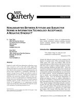
Figure 1 shows examples of specified transmission paths used in generic balanced cabling.
The channel is the transmission path between equipment such as a LAN switch or hub and
the terminal equipment. The channel does not include the connections at the data source
equipment and the terminal equipment. The channel, the permanent link or the CP link shall
meet the transmission requirements specified in the design standards.
Remote power may be provided to terminal equipment via balanced cabling equipment
interfaces. Remote power may be introduced to the balanced cabling channel at the FD using
spare pairs, if available, or by remote power supplied over the phantom circuit of data pairs
from the power sourcing equipment, as shown in Figure 1.
Powered Switch/Hub Powered Terminal Equipment
signal signal
signal signal
signal signal
signal balanced pair signal
power power
source sink
Powered Terminal Equipment
Powered Switch/Hub
signal signal
power power
source sink
signal signal
IEC
Figure 1 – Examples of end point powering systems
using signal pairs (top) and spare pairs (bottom)
Alternatively, remote power may be supplied by mid-span power source equipment that
inserts remote power independent of the data source equipment, as shown in Figure 2.
ISO/IEC TS 29125:2017 © ISO/IEC 2017 – 15 –
Unpowered Switch/Hub Midspan Power Insertion Powered Terminal Equipment
signal signal
signal
signal signal
signal
signal power
sink
signal Powered Terminal Equipment
signal
balanced pair power
source
Unpowered Switch/Hub Midspan Power Insertion
signal
power power
source sink
signal signal
IEC
Figure 2 – Examples of mid-span powering systems
When mid-span power source equipment replaces a generic balanced cabling component or
components, the data pairs shall meet the performance requirements of the component or
components it replaces (e.g. patch cord, patch panel or combination thereof), regardless of
the equipment interfaces used for input and output connections. Placement of mid-span power
insertion equipment shall be external to the permanent link, see ISO/IEC TR 24746.
8 Connecting hardware
Connecting hardware in channels used to support remote power applications shall have an
appropriate current rating when mated. Connecting hardware contacts may deteriorate as a
result of mating or un-mating under electrical load, leading to possible degradation of
transmission characteristics (see IEC 60512-99-001). Manufacturers should be consulted
regarding the number of mating and un-mating cycles supported by connecting hardware
while conveying the intended levels of electrical power.
The temporary removal of remote power should be considered before mating or un-mating
connecting hardware in a remotely powered channel.
It is preferable that remote powering is not present during mating or un-mating of connecting
hardware.
– 16 – ISO/IEC TS 29125:2017 © ISO/IEC 2017
Intelligent powering systems such as Power over Ethernet and Power over Ethernet-plus
(defined in ISO/IEC/IEEE 8802-3) automatically recognize compliant loads before applying the
required level of remote power, thus eliminating electrical stress during connector mating.
ISO/IEC/IEEE 8802-3 also defines optional features to remotely manage the provision of
electrical power to each port via port power management which can be used to remove
remote power from a particular channel prior to un-mating connectors.
Port power management is therefore the preferred approach to reconfiguration of remotely
powered cabling channels.
Where it is not practicable to switch off the remote power before mating or un-mating (e.g. for
power sources that do not have power management), connecting hardware having the
required performance for mating and un-mating under the relevant levels of electrical power
and load should be chosen. These requirements are not within the scope of the balanced
connecting hardware standards (e.g. IEC 60603-7, IEC 61076-3-104 and IEC 61076-3-110)
referenced from ISO/IEC 11801-1 and equivalent standards but may be assessed using
additional test schedules.
NOTE A test schedule for engaging and separating connectors under electrical load is described in
IEC 60512-99-001.
ISO/IEC TS 29125:2017 © ISO/IEC 2017 – 17 –
Annex A
(informative)
Mitigation considerations for installed cabling
A.1 General
Installed cabling is not easy to change to support new applications with additional
requirements. Annex A offers some considerations that can be useful to provide remote power
over existing installations of Class D or better balanced cabling. Consideration should be
given to local heat dissipation conditions, for instance going through framed wall construction
or through insulating material.
A.2 Minimum cabling class
Class D is the minimum cabling suitable for remote powering. Better balanced cabling is
recommended to allow higher power needed by emerging applications such as next
generation WAPs and outdoor heated PTZ cameras.
A.3 Bundle size and location
Cables with improved thermal characteristics may be configured into larger bundles. The
location of a cable bundle is also an important consideration. Conduits sealed at both ends
typically retain more heat than open conduits, leading to a higher temperature rise in the
sealed conduit. If cables are installed in an open tray, the temperature rise will be lower than
the temperature rise in conduits (sealed or unsealed) for the same bundle size.
A.4 Mitigation options
If an existing installation does not meet the current capacity in this document for a particular
bundle size, the following mitigation options may be considered.
a) Use only half the cables in a bundle for remote powering with the other half used for
applications that do not need remote power.
b) If ambient temperatures are high, consider adding air-conditioning or air-circulation over
cabling segments that are exposed to high temperature.
c) If possible, separate larger bundles into smaller bundles.
If it is not possible to implement any of the mitigation options listed above, and the number of
data terminals requiring remote powering is significant, upgrade the installation using cables
with improved thermal characteristics.
Additionally, when the number of data terminals requiring remote powering is significant,
upgrade the installation using the appropriate installation procedures to keep the bundle size
reasonably low (e.g. 24 cable count) to allow proper heat dissipation all along the channel,
permanent link or CP link.
– 18 – ISO/IEC TS 29125:2017 © ISO/IEC 2017
Annex B
(informative)
Modelling temperature rise for cable types,
bundle sizes and installation conditions
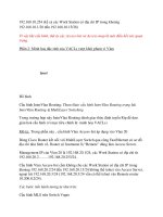
B.1 Model basics
This model derives the temperature rise based on measured data for different cable types and
installation environments:
a) ∆T is the total temperature rise between the ambient temperature (or that of the
unpowered bundle) and the centre of the bundle;
b) ∆Tth is the temperature rise between the outer surface and the centre of the bundle;
c) ∆Tu is the temperature rise between the ambient temperature (or that of the unpowered
bundle) and the outer surface of the bundle.
∆ T ∆Tt h
∆Tx
x
∆Tu
IEC
Figure B.1 – Temperature rise profile
An additional element of the model provides a calculation for the temperatures within the
bundle at a distance x from the centre (∆Tx).
B.2 Power dissipated (P)
The model uses a common factor which is defined as P:
P = N × nc × ic2 × R (B.1)
where remote
ic is the current per conductor (A) = 0,5 times the current delivered by a pair;
nc is the number of conductors per cable carrying remote powering current (ic)
= 2 times the number of pairs carrying remote powering current;
N is the number of cables carrying remote powering current;
R is the average DC resistance per unit length (Ω/m) of conductors carrying
powering current.